Table of Contents

Subscribe to Our Youtube Channel
Summary of Contents for Myson 6-4
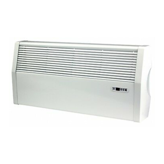
- Page 1 Installation, Operating, Maintenance and After Sales Manual. LO-LINE RC & LO-LINE RC Heater/Cooler Models: 6-4, 9-6, 14-10, 19-15 heatingthroughinnovation. Product Serial Number: Please leave this manual with the end user. Part Number: 1370057 Issue 5...
-
Page 2: Table Of Contents
Contents General Information Heating System Design Unit Selection/Sizing Location Preparation Fixing Water Connections Electrical Connection Commissioning Procedure 10.0 Technical Data 11.0 Operating Instructions 12.0 Troubleshooting 13.0 Maintenance... -
Page 3: General Information
LO-LINE RC & LO-LINE RC Heater/Cooler 1.0 General Information l This MYSON LO-LINE fan convector is designed for wall Automatic – the desired room temperature is programmed in mounted installation with a minimum installation height of to the unit and the fan speed is automatically adjusted until 150mm to the underside of the unit. -
Page 4: Preparation
LO-LINE RC & LO-LINE RC Heater/Cooler 5.0 Preparation Before proceeding with the installation, unpack the carton contents and check against the checklist below: 1. LO-LINE or LO-LINE Heater/Cooler unit. 2. 15mm isolating valves (1 pair). 3. Instruction manual. 4. Warranty card. 5. -
Page 5: Water Connections
LO-LINE RC & LO-LINE RC Heater/Cooler 7.0 Water Connections l Connect unit to system flow and return pipes using the two LO-LINE Heater/Cooler installations with chilled water will 15mm isolating valves (see fig. 3). require provision for condensate disposal in accordance with any local regulations. -
Page 6: Electrical Connection
LO-LINE RC & LO-LINE RC Heater/Cooler 8.0 Electrical Connection WARNING: This appliance must be earthed. The electrical installation must comply with local or national wiring regulations. l This unit is supplied with factory fitted test leads. Remove l Connect live and neutral wires to the power board terminal these and discard. - Page 7 LO-LINE RC & LO-LINE RC Heater/Cooler 9.0 Commissioning Procedure (continued...) Heat Pump and Low Water Temperature Systems The displayed temperature calibration function enables calibration in heating mode of the displayed temperature to the In heating mode, the control system brings the fan on when the actual room temperature using the following procedure: water in the coil reaches 32°C.
-
Page 8: Technical Data
LO-LINE RC & LO-LINE RC Heater/Cooler 10.0 Technical Data Heating Performance Data Heat Output (watts) Heat Output (Btu/h) Model Fan Speed Temperature Difference (°C) Temperature Difference (°F) 40° 45° 50° 55° 60° 65° 72° 81° 90° 99° 108° 117° Normal 2921 3268 3613... -
Page 9: Operating Instructions
LO-LINE RC & LO-LINE RC Heater/Cooler 11.0 Operating Instructions Description In manual mode, with water temperature control, any of the 3 fan speeds can be selected and the fan will operate when the water temperature in the coil is greater than 32°C. This means This LO-LINE unit is fitted with a control system that provides that heating performance can be controlled manually, and the 3 different operating modes. -
Page 10: Troubleshooting
12.0 Troubleshooting Once installed this fan convector becomes part of a complete Note: If you call out MYSON Service to a fault detailed opposite, heating system that will generally include a boiler, pump, other or to repair a fault caused by incorrect use, a call out charge will emitters such as radiators and fan convectors, and a number of be made. -
Page 11: Maintenance
Note: Operation of fan convector can be checked by water sensor switching to manual fan setting If the fan convector is still faulty after checking the above, call your installer or MYSON Service. Common Installation Faults heat, and the heating system must be correctly designed to... - Page 12 Serial Number Location: Inner chassis position heatingthroughinnovation. After Sales Service: MYSON Service, Somerden Road, Hull, East Yorkshire HU9 5PE T: 01482 713927, F: 01482 789056, service.convectors@myson.co.uk Spare parts and technical help on all Convector products are available from MYSON Service.


Need help?
Do you have a question about the 6-4 and is the answer not in the manual?
Questions and answers