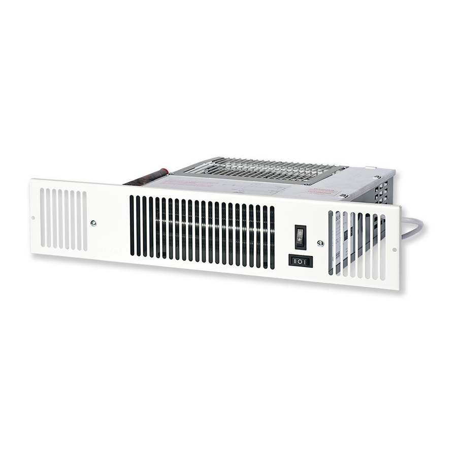
Myson KICKSPACE 500 Installation Maintenance And Operating Instructions
Fan convectors
Hide thumbs
Also See for KICKSPACE 500:
- Installation & operation manual (12 pages) ,
- Installation & operating manual (12 pages) ,
- Manual (10 pages)
Table of Contents
Advertisement
Quick Links
KICKSPACE 500, 600 and 600-12V
INSTALLATION, MAINTENANCE AND
PLEASE READ THESE INSTRUCTIONS THOROUGHLY BEFORE BEGINNING INSTALLATION.
AFTER INSTALLATION LEAVE THESE INSTRUCTIONS WITH THE USER AND COMPLETE THE
PRODUCT SERIAL NUMBER DETAILS IN THE BOX BELOW.
®
FAN CONVECTORS
OPERATING INSTRUCTIONS
AND TECHNICAL DATA
1370036 - 05
B.E.A.B.
Approved
Advertisement
Table of Contents

Summary of Contents for Myson KICKSPACE 500
-
Page 1: Operating Instructions
1370036 - 05 ® KICKSPACE 500, 600 and 600-12V FAN CONVECTORS INSTALLATION, MAINTENANCE AND OPERATING INSTRUCTIONS AND TECHNICAL DATA PLEASE READ THESE INSTRUCTIONS THOROUGHLY BEFORE BEGINNING INSTALLATION. AFTER INSTALLATION LEAVE THESE INSTRUCTIONS WITH THE USER AND COMPLETE THE PRODUCT SERIAL NUMBER DETAILS IN THE BOX BELOW. -
Page 2: Table Of Contents
LIST OF CONTENTS Application ............... Page 2 Electrical Supply ..............3 Preparation ................. 3 Water Connections ............. 4 Fitting Kickspace ..............4 Completion ................5 Controls ................5 Operation ................6 Maintenance ............... 6 10. Technical Data ..............7 11. Wiring Diagrams ..............7 1. -
Page 3: Electrical Supply
Note: If the supply cord to the transformer is damaged, it must be replaced by a special cord/transformer assembly available from Myson Convectors. ELECTRICAL SUPPLY - continued Kickspace 500 and 600 Kickspace 600-12V Fig. 2.2 - Electrical supply 3. PREPARATION 3.1 A clean and level floor area is required under the cupboard or bath base. -
Page 4: Water Connections
4. WATER CONNECTIONS WATER CONNECTIONS - continued 4.1 Connect flexible pipes to the system flow and 4.2 Connect the valve ends of the flexible pipes to return pipes. the rear of the Kickspace. Note: The direction of flow arrows on the valves are not significant in this application. -
Page 5: Completion
6. COMPLETION COMPLETION - continued 6.1 Align the grille and secure it to the unit with two 6.2 Secure the unit/grille to the plinth with two screws supplied (use the shorter screws). screws supplied (use the longer screws). Front view of unit Front view of unit Unit securing screws Grille securing screws... -
Page 6: Operation
8. Operation Ensure that the electrical supply is switched on. 8.1. Winter use - for heating If remote room thermostat is fitted, turn it to a high setting. Set the fan speed switch to Boost or Low, see Fig. 7. Set the Summer/Winter switch, see Fig. -
Page 7: Technical Data
Test pressure: 20 bar, Maximum working pressure: 10 bar Water connections: 15 mm compression Electrical supply: 220 - 240 V ~ 50 Hz 11. WIRING DIAGRAMS Kickspace 500 and 600 - standard wiring diagram Kickspace 600-12V - standard wiring diagram Colour code: br-Brown, bl-Blue, bk-Black, r-Red, y-Yellow, g/y-Green/Yellow... - Page 8 The statutory rights of the consumer are not affected. © Myson Radiators Limited 2002. All rights reserved. No part of this manual may be reproduced by any means without prior written consent.


Need help?
Do you have a question about the KICKSPACE 500 and is the answer not in the manual?
Questions and answers