
Related Manuals for Lifetime 60057


Summary of Contents for Lifetime 60057
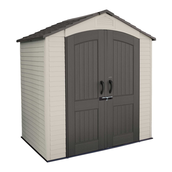
- Page 1 OUTDOOR STORAGE MODEL N° 60057 OWNER’S MANUAL Keep this Identification Number in case you must contact our Customer Service Department.
- Page 2 Plan to spend a good part of your weekend putting together your fi ne Outdoor Storage Shed. Our Lifetime© Outdoor Storage Shed will surely last a long, long time, if you are patient, and take all the time necessary to put it together as we have instructed.
- Page 3 Lifetime continues to develop innovative products that outfi t the way you live. Lifetime makes the things you need for the lifestyle you want. By innovating products in and around the home, Lifetime simplifi es your everyday life and enables you to get the most out of your free time.
- Page 4 REGISTER YOUR LIFETIME PRODUCT TODAY! There are benefi ts to registering your Lifetime product. With our new online product registration form, it’s fast and easy! Register with us at www.lifetime.com and enjoy these great benefi ts: promotions! But you will need to provide a sales receipt to verify your product purchase date before warranty service will be provided.
- Page 5 BEFORE BEGINNING ASSEMBLY Keep the hardware bags and their contents separate. If any parts are missing, call our Customer Service Department. Identify and inventory all parts and hardware using the parts and hardware lists and identifi ers in this document. *Two adults required to complete assembly* (+ one adult suggested as an instruction reader)
- Page 6 ASSEMBLY GUIDES Refer to the following areas throughout the instructions to assist in the assembly process: This area is located at the top, left-hand TOOLS AND HARDWARE REQUIRED FOR THIS PAGE corner of the page and indicates which tools and hardware are needed to complete the assembly steps on a page.
- Page 7 IMPORTANT NOTICES Level Surface Notice: Surface must be leveled before installation. We recommend building a level work space with a concrete or patio style surface. If the surface is not properly leveled, the Outdoor Shed will not assemble correctly. Proper surface leveling will save you time in the long run, so please do not ignore this step. Building Code Notice: Consult all local building codes, as well as city and county ordinances, to ensure that the construction of the Outdoor Shed does not require a building permit.
- Page 8 CNW 60057 METAL KIT Wall Support Channel End Cap Entry Header Bar 1/8” Drill Bit BYK RIGHT DOOR ASSEMBLY HARDWARE CVX 60057 SMALL PARTS BOX Inside Door Handle Wood Block End Cap FLOOR ASSEMBLY HARDWARE CNV TRUSS, REAR GABLE, & ROOF INSTALLATION HARDWARE 1/4”...
- Page 9 Parts shown at 4% of actual size BYV (x1) Skylight AHD (x4) AGL (x4) Wall Panel Corner Wall Panel 60057 SMALL PARTS BOX [CVX] Parts shown at 8% of actual size (*Unless noted otherwise) BYX (x4) *AIX (x4) *BYW Roof End Cap Filter Wood Shim Roof End Cap 26 11/16”...
- Page 10 PARTS IDENTIFIER 60057 METAL KIT [CNW] Parts shown at 8% of actual size 43 1/4” 40” AFG (x1) Truss Brace 67 3/4” AFM (x4) Wall Support Channel 78 3/8” BXX (x1) Rear Wall Support Square Tube 54 3/8” AFE (x1) Entry Header Bar 70 7/8”...
- Page 11 PARTS IDENTIFIER WALL INSTALLATION HARDWARE [CNU] Hardware shown at actual size ADZ (x55) ADV (x6) 1/4” x 5/8” Pan-Head Screw 1/4” x 1 1/8” Pan-Head Screw TRUSS ASSEMBLY HARDWARE [BYD] Hardware shown at actual size 1/4” Cap Nut Parts shown at 50% of actual size BXU (x1) BXV (x1) BXW (x1)
- Page 12 PARTS IDENTIFIER DOOR & ENTRY GABLE INSTALLATION HARDWARE [BYI] Hardware shown at actual size ADZ (x17) BFY (x5) ADJ (x5) 1/4” x 5/8” Pan-Head Screw Cotter Pin 1/4” Cap Nut BXZ (x16) 1/4” Nylon Washer BYM (x1) Strike Plate RIGHT DOOR ASSEMBLY HARDWARE [BYK] Hardware shown at actual size ADW (x1) BBH (x1)
- Page 13 PARTS & HARDWARE IDENTIFIER LEFT DOOR ASSEMBLY HARDWARE [BYJ] Hardware shown at actual size ADW (x5) CHK (x1) AEE (x7) BZB (x4) BBH (x1) 1” Square End Cap ARA (x1) 1/8” Drill Bit Deadbolt Latch Deadbolt Latch Bracket BYS (x1) BYR (x1) Outer Door Handle Inner Door Handle...
- Page 14 PARTS & HARDWARE IDENTIFIER LATCH INSTALLATION HARDWARE [CVP] Hardware shown at actual size ADX (x9) 1/4” Centerlock Nut 1/4” Flat Washer AEE (x9) Hardware shown at same scale CVW (x1) Door Latch CVT (x1) CVU (x1) CVV (x1) Large Right Door Latch Bracket Left Door Latch Bracket Small Right Door Latch Bracket CVR (x1)
- Page 15 PARTS IDENTIFIER BOX 2 60057 SHED PARTS BOX Parts shown at 4% of actual size AGQ (x4) Roof Panel Outer Floor Panel AGO (x1) AGZ (x1) Left Door Right Door AGF (x1) AGH (x1) AGI (x1) Part shown at 8% of actual size...
- Page 16 TOOLS AND HARDWARE REQUIRED FOR THIS PAGE Concrete (1 cu. yd.) SITE PREPARATION - CONCRETE PLATFORM PREPARATION The actual dimensions of your shed (at its widest and deepest points) are 7’ x 4’ 8”. Ensure you select a site that will accommodate these measurements.
-
Page 17: Wood Platform Assembly
TOOLS AND HARDWARE REQUIRED FOR THIS PAGE 2” x 4” x 81 1/2” Treated Board 2” x 4” x 52 1/4” Treated Board (x7) 16d 3” Common Nail ALTERNATIVE SITE PREPARATION: OPTION 1 - WOOD PLATFORM ASSEMBLY Ensure you use lumber that is treated and approved for outdoor use. Build outside frame to 81 1/2” Wide x 55 1/4” Deep. - Page 18 TOOLS AND HARDWARE REQUIRED FOR THIS PAGE 8d 1 1/2” Common Nail 48” x 55 1/4” x 3/4” 33 1/2” x 55 1/4” x 3/4” Treated Plywood (x1) Treated Plywood (x1) ALTERNATIVE SITE PREPARATION: OPTION 1 - WOOD PLATFORM ASSEMBLY (CONT.) Square up the frame by measuring from corner to corner.
- Page 19 TOOLS AND HARDWARE REQUIRED FOR THIS PAGE 2” x 4” x 81 1/2” 2” x 6” x 48 1/4” L-Bracket (x4) 8d 1 1/2” Common Nail (x16) Pea Gravel (7.5 Cubic Feet) ALTERNATIVE SITE PREPARATION: OPTION 2 - FILLED WOOD FRAME ASSEMBLY Lay boards fl...
- Page 20 FLOOR ASSEMBLY HARDWARE REQUIRED HARDWARE BAG REQUIRED: BYC Hardware shown at actual size BQC (x4) ADC (x1) Door Hinge Bushing PLASTIC PARTS REQUIRED Parts shown at 4% of actual size Outer Floor Panel TOOLS REQUIRED HARDWARE BAG REQUIRED: BYC ADC (x1) Phillips Screwdriver Safety Glasses...
- Page 21 TOOLS AND HARDWARE REQUIRED FOR THIS PAGE FLOOR ASSEMBLY Lay an Outer Floor Panel (AGR) fl at on the ground. Hold the second Outer Floor Panel (AGR) at an angle as shown and fi t the tabs on one Panel into the slots of the other. Lay the Outer Floor Panel fl at. CAUTION Sharp objects may damage your fl...
- Page 22 TOOLS AND HARDWARE REQUIRED FOR THIS PAGE BQC (x4) Face the seam of the two adjacent Floor Panels. Insert one (1) #8 x 1/2” Pan-Head Screw (BQC) into each divot near the ends of the seam of the Outer Floor Panels and down into the tab of the adjacent Outer Floor Panel at the locations indicated.
- Page 23 TOOLS AND HARDWARE REQUIRED FOR THIS PAGE IF YOU PLAN ON ANCHORING YOUR SHED, CHECK WITH YOUR LOCAL HARDWARE STORE FOR SUITABLE HARDWARE. ANCHORING THE SHED If you plan on anchoring the shed, anchor it to your platform through the four indentations near the corners of the fl...
- Page 24 TRUSS ASSEMBLY HARDWARE REQUIRED HARDWARE BAG REQUIRED: BYD Hardware shown at actual size 1/4” Cap Nut Part shown at 50% of actual size BXU (x1) BXV (x1) BXW (x1) Truss Connector A Truss Connector B Truss Connector Bracket 9 3/4” ADH (x1) 1/4”...
- Page 25 TOOLS AND HARDWARE REQUIRED FOR THIS PAGE ADY (x4) ADK (x4) TRUSS ASSEMBLY Insert four (4) #10 x 3/8” Pan-Head Screws (ADY) through a Truss Connector A (BXU) as shown. Truss Gutter Channels (AFH) over the Truss Connector as shown and insert the four Screws through the #10 Cap Nuts (ADK).
- Page 26 TOOLS AND HARDWARE REQUIRED FOR THIS PAGE ADY (x4) ADK (x4) Insert a Truss Connector Bracket (BXW) into the slot in Truss Connector A as shown. Place Truss Connector B (BXV) four (4) #10 x 3/8” Pan-Head Screws (ADY) through a Truss Connector B as shown and lightly secure the Screws with four (4) #10 Cap Nuts (ADK).
- Page 27 TOOLS AND HARDWARE REQUIRED FOR THIS PAGE 7/16” 3/8” ADY (x4) ADK (x4) With the Truss Assembly on its side, align the holes in a Truss Brace (AFG) as shown. Secure with four (4) #10 x 3/8” Pan-Head Screws (ADY) and four (4) #10 Cap Nuts (ADK). Hand tighten only in this step.
- Page 28 WALL INSTALLATION HARDWARE REQUIRED HARDWARE BAG REQUIRED: CNU Hardware shown at actual size ADZ (x55) ADV (x6) 1/4” x 5/8” Pan-Head Screw 1/4” x 1 1/8” Pan-Head Screw METAL PARTS REQUIRED METAL PARTS KIT REQUIRED: CNW Parts shown at 8% of actual size 67 3/4”...
- Page 29 TOOLS AND HARDWARE REQUIRED FOR THIS PAGE *AIW (x1) Wood Block ADZ (x5) WALL PANEL INSTALLATION Insert the tabs at the bottom of a Corner Wall Panel (AGL) into the holes in the slots on the front of the right, front corner of the Floor as shown.
- Page 30 TOOLS AND HARDWARE REQUIRED FOR THIS PAGE *AIW (x1) Wood Block ADZ (x15) Slide and snap another Corner Wall Panel (AGL) into place in the same manner as you did earlier. Fasten with the required hardware. If necessary, place the Wood Block (AIW) underneath the Floor, directly below the tab to be inserted, when snapping the tabs in place.
- Page 31 TOOLS AND HARDWARE REQUIRED FOR THIS PAGE *AIW (x1) Wood Block ADZ (x10) Fold a Corner Wall Panel (AGL). Slide and snap it into place in the same manner as you did earlier. Fasten with the required hardware. If necessary, place the Wood Block (AIW) underneath the Floor, directly below the tab to be inserted, when snapping the tabs in place.
- Page 32 TOOLS AND HARDWARE REQUIRED FOR THIS PAGE *AIW (x1) Wood Block Fold a Corner Wall Panel (AGL). Slide and snap it into place in the same manner as you did earlier. Fasten with the required hardware. If necessary, place the Wood Block (AIW) underneath the Floor, directly below the tab to be inserted, when snapping the tabs in place.
- Page 33 TOOLS AND HARDWARE REQUIRED FOR THIS PAGE ADV (x6) Align the holes in the Rear Wall Support Square Tube (BXX) with the screw bosses along the top of the rear Wall Panels as shown. Secure the Rear Wall Support Tube to the Wall Panels using six (6) 1/4” x 1 1/8” Pan-Head Screws (ADV). Tighten securely, but do not overtighten.
- Page 34 LEFT DOOR ASSEMBLY HARDWARE REQUIRED HARDWARE BAG REQUIRED: BYJ Hardware shown at actual size ADW (x5) BBH (x1) 1” Square End Cap AEE (x7) CHK (x1) ARA (x1) 1/8” Drill Bit BZB (x4) Deadbolt Latch Deadbolt Latch Bracket BYR (x1) BYS (x1) Inner Door Handle Outer Door Handle...
- Page 35 LEFT DOOR ASSEMBLY (CONT.) PLASTIC PARTS REQUIRED Part shown at 4% of actual size AGO (x1) Left Door TOOLS REQUIRED HARDWARE BAG REQUIRED: BYJ Plain Phillips 7/16” 3/8” Electric Drill Rubber Mallet 1/8” Drill Bit (ARA) (x1) Safety Glasses Screwdriver Screwdriver Wrench Wrench...
Need help?
Do you have a question about the 60057 and is the answer not in the manual?
Questions and answers