
Related Manuals for Oceanic OC1


Summary of Contents for Oceanic OC1
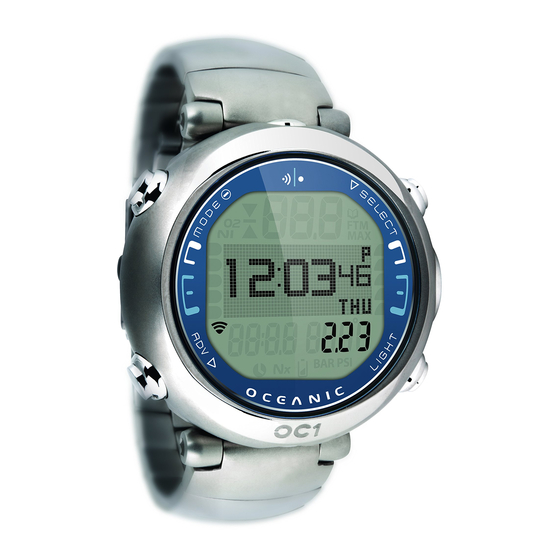
- Page 1 OC1 OPERATING MANUAL DIVE COMPUTER OPERATING MANUAL © 2002 Design, 2009 Doc. No. 12-2761-r04 (9/6/11)
-
Page 2: Table Of Contents
OC1 OPERATING MANUAL CONTENTS NOTICES....................3 DIVE.MODE.FEATURES..............26 NORM.Dive.Mode.Structure............27 FEATURES.AND.FUNCTIONS..............5 PROXIMITY.OF.THE.TMTS.AND.OC1..........27 DISPLAY.LAYOUT................6 Link.Interruption.Underwater............27 ABBREVIATIONS................6 WET.ACTIVATION................28 INITIAL.ACTIVATION.................6 BACKLIGHT..................28 BAR.GRAPHS.................28 OVERVIEW..................7 TLBG....................28 MENU.SYSTEM.................7 O2BG...................28 OPERATING.MODE.STRUCTURES..........8 VARI.....................28 ALGORITHM.(NDL.BASIS).............29 AUDIBLE.ALARM................9 CONSERVATIVE.FACTOR..............29 PC.INTERFACE.................9 DEEP.STOP..................29... -
Page 3: Notices
DECOMPRESSION MODEL The programs within the OC1 simulate the absorption of nitrogen into the body by using a mathematical model. This model is merely a way to apply a limited set of data to a large range of experiences. The OC1 dive computer model is based upon the latest research and experiments in decompression theory. Still, using the OC1, just as using the U.S. Navy (or other) No Decompression Tables, is no guarantee of avoiding decompression sickness, i.e. - Page 4 OC1 OPERATING MANUAL Welcome OCEANIC THANK YOU for choosing the © 2002 Design, 2009 Doc. No. 12-2761-r04 (9/6/11)
-
Page 5: Features.and.functions
OC1 OPERATING MANUAL FEATURES FUNCTIONS © 2002 Design, 2009 Doc. No. 12-2761-r04 (9/6/11) -
Page 6: Display.layout
INITIAL ACTIVATION OC1 Watch/Dive Computers are placed in a Deep Sleep mode prior to being shipped from the factory. The intent is to extend storage life of the Battery for up to 7 years, before the unit is initially placed in service. -
Page 7: Overview
• User Upgradeable Firmware INTERACTIVE CONTROL CONSOLE The Interactive Control Console utilizes 4 control buttons that allow you to maneuver through the OC1's unique system of menus. The buttons will be referred to as M, S, L, and A. • Upper/Left - Mode (M) button •... -
Page 8: Operating.mode.structures
OC1 OPERATING MANUAL WATCH MODE STRUCTURE NORM SURFACE MODE STRUCTURE Watch Dive Op Daily AL Mode Mode Pg. 37 Pg. 32 Pg. 45 2 sec 2 sec < 2 sec Select NORM Compass < 2 sec 2 sec Select Watch Compass <... -
Page 9: Audible.alarm
• On the Surface for 5 minutes after a Conditional Violation. PC INTERFACE Interface with a PC, to allow uploading settings and downloading data, is accomplished by connecting the OC1 to a PC USB Port using the special OC1 USB Interface Cable. -
Page 10: Power.supply,.Battery.status
• A (< 2 sec), repeat until ( > ) is next to BATT/TMT • S (< 2 sec) activates Receiver, then OC1 Status appears for 3 sec (Fig. 1A), then each TMT Status for 3 sec (Fig. 1B). OC1 LOW BATTERY WHILE ON THE SURFACE <= 2.75 volts (warning level) -
Page 11: Watch.mode
OC1 OPERATING MANUAL WATCH MODE © 2002 Design, 2009 Doc. No. 12-2761-r04 (9/6/11) -
Page 12: Watch.default.time
OC1 OPERATING MANUAL WATCH DEFAULT TIME Default Time is the Time that is displayed on the Watch until changed. It is also the Time viewed during operation in DC (Dive Computer) Modes. Main Time is the current Time at your home location and is normally selected as the Watch Default Time. -
Page 13: Chronograph
OC1 OPERATING MANUAL Set CDT, information includes (Fig. 13): > Graphics SEt and CD TMR > CDT (hr:min) with Hour digits flashing > Time (clock) icon • A (hold) to scroll upward through Hour Set Points at a rate of 8 per second from 0: to 23: in increments of 1: (hr). -
Page 14: Set.time.menu
OC1 OPERATING MANUAL SET TIME MENU • S (< 2 sec) to access Set Time Menu, while the selection Arrow icon ( > ) is next to Set Time on the Watch Menu • A (< 2 sec) to step down (forward) through selections •... -
Page 15: Select.default.time
OC1 OPERATING MANUAL Select Default Time, information includes (Fig. 25): This feature selects whether Main (home) Time or Alternate (travel location) Time will be displayed as the Watch Default Time. The other will be displayed on the Watch ALT 1 screen. -
Page 16: Norm.surface.modes
OC1 OPERATING MANUAL NORM SURFACE MODES © 2002 Design, 2009 Doc. No. 12-2761-r04 (9/6/11) -
Page 17: Dive.computer.operating.modes
OC1 OPERATING MANUAL NORM SURFACE FUNCTIONS Watch.Mode 2 sec Compass NORM 2 sec SURF.MAIN Surface.ALTs < 2 sec WATCH Light DFLT.TIME 2 sec closure < 2 sec 2 sec NORM MENU FLY/DSAT PLAN < 2 sec SET.F SET.A SET.U < 2 sec >... -
Page 18: Norm.surf.main.and.alts
OC1 OPERATING MANUAL NORM SURF MAIN, information includes (Fig. 26A/B): > Graphic NORM > Graphic DIVE and number of dives completed during that operating period, up to 24 (0 if no dive made yet) > Graphic SURF and SI (hr:min) with Time (clock) icon; if no dive yet, this is time since access to NORM >... -
Page 19: Norm.plan.mode
OC1 OPERATING MANUAL Fly/Dsat, information includes (Fig. 30A/B): > Time to Fly (hr:min), 0:00 if no dive yet, with graphic FLY > Time to Desat (hr:min), 0:00 if no dive yet, with graphic DSAT > Time (clock) icon • S < 2 sec, revert to Menu •... -
Page 20: Set.f.(Fo2).Menu
OC1 OPERATING MANUAL Log Data 1, information includes (Fig. 34): > Log Mode (book) icon > Max Depth** with MAX and FT (or M) icons > Graphic DSAT (or PZ+), the NDL Basis (algorithm selected) > Graphic EDT with Dive Time (hr:min) >... -
Page 21: Set.fo2.Gas.3
OC1 OPERATING MANUAL Set FO2 Gas 3, information includes (Fig. 38): > Max Depth with MAX and FT (or M) icons, allowed for PO2 Alarm Set, blank if Air > Graphic GAS2 > Graphic FO2 with FO2 Set Point value, flashing >... -
Page 22: Set.tlbg.alarm
OC1 OPERATING MANUAL Set TLBG Alarm, information includes (Fig. 43): > Graphic TLBG AL > Depth value flashing with MAX and FT (or M) icons • A (< 2 sec) to step upward through Set Points from 1 to 5 segments one at a time •... -
Page 23: Set.units
OC1 OPERATING MANUAL Set Units, information includes (Fig. 49): > Graphic UNITS > Set Point graphics IMPERIAL and METRIC; Arrow ( > ) icon next to the one previously saved flashing • A (< 2 sec) to toggle Set Points •... -
Page 24: Set.sampling.rate
OC1 OPERATING MANUAL Set Sampling, information includes (Fig. 55): > Set Point graphics 2 SEC, 15 SEC, 30 SEC, and 60 SEC; Arrow ( > ) icon next to the one previously saved flashing • A (< 2 sec) to step upward through Set Points one at a time •... -
Page 25: Select.dive.mode
TMT Status (not reporting), information includes (Fig. 64B): > Graphic TMT1 (or 2 or 3) > Graphic NOT AVAIL This screen appears when the OC1's receiver is not receiving a signal from a TMT, or the TMT is set Off. Fig. 64B - TMT NOT REPORTING ©... -
Page 26: Dive.mode.features
OC1 OPERATING MANUAL DIVE MODE FEATURES © 2002 Design, 2009 Doc. No. 12-2761-r04 (9/6/11) -
Page 27: Norm.dive.mode.structure
The TMTs emit low frequency signals that radiate out in semicircular patterns parallel to the length dimension of the TMT. A coiled antenna inside the OC1 receives the signals when it is positioned within a zone parallel to or at a 45 degree angle to the TMT as illustrated. -
Page 28: Wet.activation
24 hour period. The OC1 will store O2 calculations for up to 10 dives conducted during a 24 hour period. If the limit for O2 is reached (100% = 300 OTU), all 5 segments of the O2BG will be displayed on the Main dive screen in place of the TLBG (Fig. 68a). -
Page 29: Algorithm.(Ndl.basis)
FO2 Gas 1 will continue to reset to the FO2 50% Default after subsequent repetitive dives until 24 hours elapse after the last dive, or the FO2 50% Default is set Off. When the FO2 50% Default is set Off, the OC1 will remain set at the last FO2 Gas 1 Set Point for that period of activation. © 2002 Design, 2009... -
Page 30: Fo2.Set.for.air
50%. • The OC1 is programmed to prevent FO2 Gas 2 and 3 from being set at values lower than the FO2 Set Point for Gas 1. Gas 2 and Gas 3 require Set Points equal to/higher than Gas 1 and Gas 2, respectively. -
Page 31: Error.(Reset.during.dive)
ERROR (RESET DURING A DIVE) If for any reason, the OC1 shuts Off then turns On again during any Dive, the graphic ERR (Error) will be displayed with the Up Arrow icon and current Depth with FT (or M) icon (Fig. 75A). -
Page 32: Norm.dive.modes
OC1 OPERATING MANUAL NORM DIVE MODES © 2002 Design, 2009 Doc. No. 12-2761-r04 (9/6/11) -
Page 33: No.deco.main.and.alts
OC1 OPERATING MANUAL NO DECO MAIN, information includes (Fig. 76) - > Current Depth with FT (or M) icon > DTR (hr:min) with graphic NDC (or OTR or AIR), whichever is less at the time > ATR (min) when 60 minutes or less with graphic ATR and Time (clock) icon, blank if no TMT or ATR is DTR >... -
Page 34: Safety.stop
OC1 OPERATING MANUAL Deep Stop Alt 2, information includes (Fig. 82) - > Time of Day (hr:min sec), with A (or P) if 12 Hour > Temperature with ° icon and graphic F (or C) • 5 sec or A (< 2 sec), revert to Main SAFETY STOP MAIN, information includes (Fig. -
Page 35: Violation.modes
OC1 OPERATING MANUAL • A (< 2 sec) to access ALTs • M (2 sec) to access Gas Switching • S (< 2 sec) to acknowledge alarms • S (2 sec) to access Compass • L (closure) to activate Backlight Deco Stop Alt 1, information includes (Fig. - Page 36 If a Deco Stop Depth greater than 70 FT (21 M) is required, operation will enter VGM. This would be preceded by DV2. Operation would then continue in VGM during the remainder of that dive and for 24 hours after surfacing. VGM turns the OC1 into a digital instrument without any decompression or oxygen related calculations or displays.
-
Page 37: High.po2
OC1 OPERATING MANUAL VGM Alt 1, information includes (Fig. 97) - > Max Depth with MAX and FT (or M) icons > Graphic EDT with Elapsed Dive Time (hr:min) • A (< 2 sec) to access ALT 2 • Revert to Main in 5 sec, if A not pressed VGM Alt 2, information includes (Fig. -
Page 38: High.o2
OC1 OPERATING MANUAL PO2 Alarm Alt 2, information includes (Fig. 103) - > Time of Day (hr:min sec), with A (or P) if 12 Hour > Temperature with ° icon and graphic F (or C) • 5 sec or A (< 2 sec), revert to Main PO2 during Deco The PO2 alarm setting does not apply when in Deco. - Page 39 If you are following these dive profiles, Oceanic advises that you should not use an OC1. If you exceed certain limits, the OC1 will not be able to help you get safely back to the surface. These situations exceed tested limits and can result in loss of some functions for 24 hours after the dive in which a violation occurred.
-
Page 40: Gas/Tmt.switching
OC1 OPERATING MANUAL GAS/TMT SWITCHING © 2002 Design, 2009 Doc. No. 12-2761-r04 (9/6/11) - Page 41 OC1 OPERATING MANUAL OVERVIEW > Can only switching when Dive Main screens are displayed. > Cannot Switch Gas or TMTs on surface. > Cannot Switch Gas or TMTs during alarms. > All NORM dives begin with Gas 1. > NORM mode defaults to Gas 1 after 10 minutes on the surface.
- Page 42 OC1 OPERATING MANUAL DIGITAL GAUG MODE STRUCTURE SURFACE Watch. 2 sec Mode GAUG. Compass 2 sec SURF. MAIN Surface. ALTs < 2 sec closure Light < 2 sec 2 sec Menu access > selection < 2 sec SET.A < 2 sec SET.U...
-
Page 43: Digital.gauge.mode
OC1 OPERATING MANUAL DIGITAL GAUGE OP MODE © 2002 Design, 2009 Doc. No. 12-2761-r04 (9/6/11) -
Page 44: Gaug.surface.main.and.alts
OC1 OPERATING MANUAL GAUG SURF MAIN, information includes (Fig. 114, 115): > Graphic GAUG > Graphic DIVE and number of dives completed during that operating period, up to 24 (0 if no dive made yet) > Graphic SURF and SI (hr:min) with Time (clock) icon; if no dive yet, this is time since access to GAUG >... -
Page 45: Gaug.dive.main.and.alt
OC1 OPERATING MANUAL Upon descent to 5 FT (1.5 M) for 5 seconds, operation will enter GAUG Dive Mode. GAUG Dive Main, information includes (Fig. 120) - > Current Depth with FT (or M) icon > Graphic TMR with Run Time (hr:min:sec), 0:00:00 until started, up to 9:59:59 >... -
Page 46: Free Dive
OC1 OPERATING MANUAL FREE DIVE OP MODE © 2002 Design, 2009 Doc. No. 12-2761-r04 (9/6/11) -
Page 47: Free.surface.main.and.alts
OC1 OPERATING MANUAL FREE DIVE MODE STRUCTURE SURFACE DIVE Surface.Mode Watch. 2 sec Mode FREE. 2 FT (0.6 M) Compass 2 sec SURF. for 1 sec MAIN Surface. ALTs < 2 sec 5 FT (1.5 M) for 5 sec closure Light Dive.Mode... -
Page 48: Free.dive.mode
OC1 OPERATING MANUAL FREE MENU M (< 2 sec) - to access Menu, while viewing Surface Main. A (< 2 sec) - to step down (forward) through selections. M (< 2 sec) - to step up (backward) through selections. S (< 2 sec) - to access selection indicated by Arrow icon ( > ). -
Page 49: Select.dive.mode
OC1 OPERATING MANUAL Set DD2 Alarm**, information includes (Fig. 132A): > Depth value with MAX and FT (or M) icons > Graphics DD2 AL > Graphic OFF (or ON) flashing • A < 2 sec to toggle OFF/ON • S (< 2 sec) to save Set Point and flash Depth digits (if ON); or revert to FREE Menu (if OFF), bypassing DD3 ** If this screen is accessed when DD1 is set Off, a message (Fig. -
Page 50: Free.dive.main.and.alts
OC1 OPERATING MANUAL FREE Dive Main, information includes (Fig. 135) - > Current Depth with FT (or M) icon > Graphic NDC with Time Remaining (hr:min) > Graphic EDT with Elapsed Dive Time (min:sec) > TLBG with NI icon, if any from FREE or NORM dives within last 24 hours •... - Page 51 The mathematical models currently used in the OC1 are based on no decompression/decompression multilevel repetitive dive schedules. These algorithms do not take into account the physiological changes associated with the high pressures that competitive type Free diving can expose a diver to.
- Page 52 OC1 OPERATING MANUAL COMPASS MODE © 2002 Design, 2009 Doc. No. 12-2761-r04 (9/6/11)
-
Page 53: Compass.mode
OC1 OPERATING MANUAL COMPASS ICONS Diver’s Direction of Turn Left Travel Turn Right North OP Mode Tilt Heading Reference Degrees OP Mode dynamic North or Ref Heading set COMPASS MODE SURFACE 2 sec Watch.or.DC. COMP Surface.Main closure 60 sec Light... -
Page 54: Overview
> 360 with ° icon • S (< 2 sec) - to activate (start) Calibration • Slowly and steadily rotate the OC1 360° in either direction while maintaining it in a flat level position (keeping it level is Fig. 146 - START CAL critical for acurracy), CAL progress will be displayed. -
Page 55: North.op.mode
• S (< 2 sec) - to add the graphic SEt to the display with Reference Mode icon and Heading digits flashing (Fig. 151) • Slowly and steadily rotate the OC1 in either direction while maintaining it in a flat level position until the Heading (001 to 360°) required is displayed. -
Page 56: Compass.operation
OC1 OPERATING MANUAL COMPASS OPERATION Once it is Calibrated, Declination is set, the OP Mode is selected, and the course Heading is set (if Reference), the OC1 is ready for operation on the surface or underwater. • S (2 sec) - to access Compass OP Main while viewing a Surface or Dive Main screen (NORM, GAUG, or FREE) or the Watch Default Time screen North OP Main, information includes (Fig. -
Page 57: Reference
REFERENCE CAUTION: When the procedure provided in this section is used to change the OC1 Battery, you must be sure that the case o-ring is not pinched and that the OC1 is water tight before conduct- ing diving activities. Pre dive pressure testing by an Authorized Oceanic facility is highly recommended. -
Page 58: Pc.interface
A USB Driver is provided on the Oceanlog CD as part of the Interface System. Fig. 158 - OC1 DATA PORT The OC1 is configured with a Data Port located on the side (Fig. 158a) that enables it to be connected to a PC through a USB port using the special Interface Cable supplied. -
Page 59: Care.and.cleaning
Instrument Lens Protector. Small scratches will naturally disappear underwater. • Soak and rinse the OC1 in fresh water at the end of each day of diving, and check to ensure that the areas around the Low Pressure (Depth) Sensor (Fig. 160a), PC Interface Data Port (Fig. 160b), and Buttons are free of debris or obstructions. - Page 60 • Inspect the Buttons, Lens, and Housing to ensure they are not cracked or damaged. WARNING: If damage or corrosion is found, return your OC1 to an Authorized Oceanic Dealer, and DO NOT attempt to use it until it has received factory prescribed service.
-
Page 61: Transmitter
> No adjustments are made during any time that the Wet Contacts are bridged. When diving in high altitude waters from 3,001 to 14,000 feet (916 to 4,270 meters), the OC1 automatically adjusts to these conditions providing cor- rected Depth, and reduced No Deco and O2 Times at intervals of 1,000 feet (305 meters). -
Page 62: Technical.data
OC1 OPERATING MANUAL TECHNICAL DATA © 2002 Design, 2009 Doc. No. 12-2761-r04 (9/6/11) -
Page 63: Pz+.Algorithm.ndl.chart
OC1 OPERATING MANUAL PZ+ ALGORITHM >> NDLS (HR:MIN) AT ALTITUDE (IMPERIAL) Altitude 3001 4001 5001 6001 7001 8001 9001 10001 11001 12001 13001 (feet) 3000 4000 5000 6000 7000 8000 9000 10000 11000 12000 13000 14000 Depth ( FT ) 30 3:17... -
Page 64: Specifications
> Pressure < 50 PSI (3.5 BAR) TMT Compatibility with Nitrox When packaged and shipped from the factory, Oceanic TMTs are rated for use with compressed Air and Nitrox mixtures containing up to 99% O2 by volume and with 100% O2. OPERATIONAL PERFORMANCE... -
Page 65: Fcc.compliance
• Connect the equipment to an outlet on a circuit different from that to which the receiver is connected. • Consult the dealer or an experienced radio/TV technician. Warning: Changes or modifications to this unit not expressly approved by Oceanic/2002 Design could void the user's authority to operate the equipment. © 2002 Design, 2009... -
Page 66: Inspection/Service.record
Transmitter 2 Serial Number: ___________________________________________________________________________________________________ Transmitter 3 Serial Number: ___________________________________________________________________________________________________ Date of Purchase: ___________________________________________________________________________________________________ Purchased from: ___________________________________________________________________________________________________ Below to be filled in by an Authorized Oceanic Dealer: Date Service Performed Dealer/Technician OCEANIC.WORLD.WIDE OCEANIC USA 2002 Davis Street San Leandro, CA 94577... - Page 67 OC1 OPERATING MANUAL NOTES © 2002 Design, 2009 Doc. No. 12-2761-r04 (9/6/11)
-
Page 68: Dive Computer
OC1 OPERATING MANUAL DIVE COMPUTER OPERATING MANUAL © 2002 Design, 2009 Doc. No. 12-2761-r04 (9/6/11)
Need help?
Do you have a question about the OC1 and is the answer not in the manual?
Questions and answers