Table of Contents
Advertisement
Quick Links
Advertisement
Table of Contents

Summary of Contents for Delta Electronics VFD-DD Series
- Page 2 Preface Firmware Version 1.07 Thank you for choosing DELTA’s high-performance VFD-D D Series. The VFD-DD Series is manufactured with high-quality components and materials and incorporate the latest microprocessor technology available. This manual is to be used for the installation, parameter setting, troubleshooting, and daily maintenance of the AC motor drive.
- Page 3 Do NOT connect AC main power directly to the drive’s output terminals U/T1, V/T2 and W/T3. DO NOT use Hi-pot test for internal components. The semi-conductor used in the AC motor drive is easily damaged by high-pressure. A charge may still remain in the main circuit terminals with hazardous voltages, even when motor has come to stop.
- Page 4 without prior notice. Please contact your local distributors or visit our website to download the most updated version at http://www.delta.com.tw/industrialautomation/. The AC motor drive may also be called as “drive”, all drive mentioned in this manual refers to the AC motor drive.
-
Page 5: Table Of Contents
Table of Content Chapter 1 Introduction 1-1 Receiving and Inspection ....................1 - 2 1-2 Preparation for Installation and Wiring ................1 - 4 1-3 Dimensions ........................1 - 6 Chapter 2 Wiring 2-1 Wiring Diagram ........................2 - 2 2-2 Main Circuit Terminal...................... - Page 6 Group 04: Door Open Parameters .................. 4 - 4 2 Group 05: Door Close Parameter..................4 -46 Group 06: Protection and Special Parameters..............4 -51 Group 07: Control Parameters ..................4 -57 Group 08: Multi-step Speed Parameters ................. 4 -60 Group 09: Communication Parameters ................
-
Page 7: Chapter 1 Introduction
Chapter 1 Introduction |DD Series Chapter 1 Introduction 1-1 Receiving and Inspection 1-2 Preparation for Installation and Wiring 1-3 Dimensions The AC motor drive should be kept in the shipping carton or crate before installation. In order to retain the warranty coverage, the AC motor drive should be stored properly when it is not to be used for an extended period of time. -
Page 8: Receiving And Inspection
Output Frequency Range Version: 01.00 Software Version Bar Code 02DD21A0T0330003 Serial Number DELTA ELECTRONICS, INC. MADE IN TAIWAN Explanation for Model VFD 002 DD 2 1 A Function B: with brake function : without brake function Version Type A: Standard... - Page 9 Chapter 1 Introduction |DD Series Explanation for Series Number 02DD21A0 Production number Production week Production year 2007 Production factory (T: Taoyuan, W: Wujian) 230V 1-PHASE 0.25HP(0.2kW) Model...
-
Page 10: Preparation For Installation And Wiring
Chapter 1 Introduction |DD Series 1-2 Preparation for Installation and Wiring Install the AC motor drive in an environment with the following conditions: -10 ~ +45°C (14 ~ 113°F) Air Temperature: Relative Humidity: <90%, no condensation allowed Atmosphere pressure: 86 ~ 106 kPa Operation Installation Site <1000m... - Page 11 Chapter 1 Introduction |DD Series CAUTION! Mount the AC motor drive vertically on a flat vertical surface by using bolts or screws. Other directions are not allowed. The AC motor drive will generate heat during operation. Allow sufficient space around the unit for heat dissipation.
-
Page 12: Dimensions
Chapter 1 Introduction |DD Series 1-3 Dimension VFD002DD21A; VFD002DDDD21AB; VFD002DD21C; VFD002DD21CB; VFD004DD21A; VFD004DD21AB; VFD004DD21C; VFD004DD21CB; VFD002DD21E; VFD004DD21E; Unit: mm [inch] Φ1 Φ2 215.0 204.0 204.0 170.0 138.5 15.0 15.1 15.5 55.0 [8.46] [8.03] [8.03] [6.69] [5.45] [0.59] [0.59] [0.61] [2.17] [0.34] [0.20] [0.28]... - Page 13 Chapter 1 Introduction |DD Series ECMD-B9160GMS...
-
Page 14: Chapter 2 Wiring
Chapter 2 Wiring|DD Series Chapter 2 Wiring After removing the front cover, examine if the power and control terminals are clearly noted. Please read following precautions before wiring. Make sure that power is only applied to the R/L1, S/L2, T/L3 terminals. Failure to comply may result in damage to the equipments. -
Page 15: Wiring Diagram
Chapter 2 WiringDD Series 2-1 Wiring Diagram When wiring for an AC motor drive, user needs to connect wires to two sections, main circuit and control circuit. Please properly connect wires to your AC motor drive according to the circuit diagram provide in the following pages VFD-DD Basic Wiring Diagram G ND... - Page 16 Use ground leads that comply with local regulations and keep them as short as possible. No braking resistor is built in the VFD-DD series, it can install braking resistor for those occasions that use higher load inertia or frequent start/stop. Refer to Appendix B for details.
- Page 17 Chapter 2 Wiring|DD Series Damaged insulation of wiring may cause personal injury or damage to circuits/equipment if it comes in contact with high voltage. The AC motor drive, motor and wiring may cause interference. To prevent the equipment damage, please take care of the erroneous actions of the surrounding sensors and the equipment.
-
Page 18: Main Circuit Terminal
Chapter 2 Wiring|DD Series 2-2 Main Circuit Terminal Main Circuit Terminal Mo tor U/T1 V/T2 IM/PM W/T3 Wire Gauge Torque Wire Type 14-12 AWG. Stranded copper only,75℃ 5.2kgf-cm (4.5in-lbf) (2.075-3.332mm Terminal Symbol Explanation of Terminal Functions L1, L2 AC line input terminals U/T1, V/T2, W/T3 AC drive output terminals for connecting 3-phase induction motor Earth connection, please comply with local regulations. - Page 19 Chapter 2 Wiring|DD Series (Resistance-Capacitance), unless approved by Delta. DO NOT connect phase-compensation capacitors or surge absorbers at the output terminals of AC motor drives. Use a well-insulated motor, suitable for inverter operation.
-
Page 20: Control Circuit Terminal
Chapter 2 WiringDD Series 2-3 Control Circuit Terminal RA2 RB2 RA1 RB1 Torque Wire Gauge 5 kgf-com (6.9 in-lbf) 18-12 AWG (0.8107-3.332mm Terminal Terminal Function Factory Setting (NPN Mode) Symbol OD-DCM: ON: Open ; OFF: Decelerate to stop Door Open to Stop CD-DCM: ON: Close;... - Page 21 Chapter 2 Wiring|DD Series Digital Inputs (CD, OD, MI1~MI5, COM) When using contacts or switches to control the digital inputs, please use high quality components to avoid contact bounce. Digital Outputs (MO1, MO2, MO3, MCM) Make sure to connect the digital outputs to the right polarity, see wiring diagrams. When connecting a relay to the digital outputs, connect a surge absorber or fly-back diode across the coil and check the polarity.
-
Page 22: Chapter 3 Keypad And Start-Up
Chapter 3 Keypad and Startup |DD Series Chapter 3 Keypad and Start-up 3-1 Operation Method 3-2 Keypad Descriptions Make sure that the wiring is correct. In particular, check that the output terminals U/T1, V/T2, W/T3 are NOT connected to power and that the drive is well grounded. Verify that no other equipment is connected to the AC motor Do NOT operate the AC motor drive with humid hands. -
Page 23: Operation Method
Chapter 3 Keypad and Startup |DD Series 3-1 Operation Method The factory setting of VFD-DD series AC motor drive’s operation method is set to external terminal control. But it is just one of the operation methods. The operation method can be via communication, control terminals settings or optional digital keypad. -
Page 24: Keypad Descriptions
Chapter 3 Keypad and Startup |DD Series 3-2 Keypad Descriptions Descriptions of Digital Keypad Outlook Door Close Door Open Door Close Complete Door Open Complete Fault Indicate LED Disp lay Di spla ys output frequency, cu rren t, UP/DOWN Key al l para me ter sett ing s an d fau lt co nten t Select and change parameters Ent er Ke y... -
Page 25: Chapter 4 Parameter Settings
Chapter 4 Parameter Settings|DD Series Chapter 4 Parameter Settings 4-1 Summary of Parameter Settings 4-2 Summary of Detailed Parameter Settings The VFD-DD parameters are divided into 12 groups by property for easy setting. Most of the parameter settings can be done before start-up and readjustment of the parameter will not be needed. Group 00: System Parameters Group 01: Motor Parameters Group 02: Input/Output Parameters... -
Page 26: Summary Of Parameter Settings
Chapter 4 Parameter Settings|DD Series 4-1 Summary of Parameter Settings 00 System Parameters : This parameter can be set during operation. Factory Parameter Explanation Settings Setting 0: 200w Read ○ ○ ○ ○ ○ Identity Code of AC motor 00.00 2: 400w only drive... - Page 27 Chapter 4 Parameter Settings|DD Series Factory Parameter Explanation Settings Setting Read only(Different versions will display #.## ○ ○ ○ ○ ○ Software version 00.05 differently) 0~9999 ○ ○ ○ ○ ○ 00.06 Password Input 0~2:times of wrong password 0~9999 ○ ○ ○ ○ ○ 00.07 Password Set 0: No password set or successful input in Pr.00-06...
- Page 28 Chapter 4 Parameter Settings|DD Series 01 Motor Parameters : This parameter can be set during operation. Factory Explanation Settings Parameter Setting 0: No function ○ Motor Auto Tuning (PM) 01.00 1: Auto-tuning for PM motor parameters (brake locked) 2: Auto-tuning for PG offset angle without load (Pr.01.09) 3: Auto-tuning for PG offset angle with load (Pr.01.09)
- Page 29 Chapter 4 Parameter Settings|DD Series Factory Parameter Explanation Settings Setting 0.001~10.000sec 0.100 ○ 01.22 Slip Compensation Time Constant 01.23 Torque Compensation Gain 00~10 ○ ○ 0.00~10.00 0.00 ○ ○ ○ 01.24 Slip Compensation Gain 00~1000% (0:Disable) ○ ○ ○ 01.25 Slip Deviation Level 0.0~10.0sec ○...
- Page 30 Chapter 4 Parameter Settings|DD Series 02 Input/Output Parameters : This parameter can be set during operation. Factory Parameter Explanation Settings Setting 0: 2-wire mode 1 (when power is on, ○ ○ ○ ○ ○ 2-wire/3-wire Operation 02.00 operation begins) Control 1: 2-wire mode 1 (when power is on, no operation) 2: 2-wire mode 2 (when power is on,...
- Page 31 Chapter 4 Parameter Settings|DD Series Factory Parameter Explanation Settings Setting 1: AC drive in operation ○ ○ ○ ○ ○ 02.09 Multi-function Output (Relay2) ○ ○ ○ ○ ○ 02.10 Multi-function Output 2: Zero speed frequency signal (MO1) (including STOP) ○...
- Page 32 Chapter 4 Parameter Settings|DD Series...
- Page 33 Chapter 4 Parameter Settings|DD Series 03 Feedback Parameters This parameter can be set during operation. Factory Explanation Parameter Settings Setting Encoder (PG) Signal Type 0: No function ○ ○ ○ 03.00 1: ABZ 7: PWM pulse 1~25000 ○ ○ ○ Encoder pulse 03.01 Encoder Input Type Setting 0: Disable...
- Page 34 Chapter 4 Parameter Settings|DD Series 04 Door Open Parameters This parameter can be set during operation. Factory Explanation Settings Parameter Setting 04.00 Door Open by Initial Speed 0.00~120.0Hz 2.00 ○ ○ ○ ○ ○ 0~65535 (Unit: pulses number) ○ ○ ○ ○ ○ 04.01 Door Open Distance by Initial Speed 0~20.0s...
- Page 35 Chapter 4 Parameter Settings|DD Series Factory Parameter Explanation Settings Setting 0.0~150.0% (rated motor current) ○ ○ ○ ○ ○ 04.25 Current Level when unable 0.0:No function to open the door 4-11...
- Page 36 Chapter 4 Parameter Settings|DD Series 05 Door Close Parameters This parameter can be set during operation. Factory Explanation Settings Parameter Setting 0.00~120.0Hz 2.00 ○ ○ ○ ○ ○ 05.00 Door Close Initial Speed 0~65535 (Unit: pulses number) ○ ○ ○ ○ ○ 05.01 Door Close Distance by Initial Speed 0~20.0s...
- Page 37 Chapter 4 Parameter Settings|DD Series Factory Parameter Explanation Settings Setting 0.00~120.00Hz 0.00 ○ ○ ○ ○ 05.24 Door Close DC Brake Starting Frequency 0.0~150.0% (AC drive’s rated current) 100.0 ○ ○ ○ ○ ○ Door Re-open Current 05.25 Level 1 100~200% (100% is Pr.05.25 setting) ○...
- Page 38 Chapter 4 Parameter Settings|DD Series 06 Protection and Special Parameters This parameter can be set during operation. Factory Parameter Explanation Settings Setting 350.0~450.0Vdc 380.0 ○ ○ ○ ○ ○ 06.00 Software Braking Level 0~100% ○ ○ ○ ○ ○ 06.01 ED Setting of Brake Resistor ○...
- Page 39 Chapter 4 Parameter Settings|DD Series Factory Parameter Explanation Settings Setting Bit6=0 OD and CD signal are input at the same time, but without reaction. Bit6=1 OD and CD signal are input at the same time and with door opening Bit7=0 When the running signal come from an external terminal.
- Page 40 Chapter 4 Parameter Settings|DD Series Factory Parameter Explanation Settings Setting 6: Over-current at stop (ocS) ○ ○ ○ ○ ○ 7: Over voltage during acceleration ○ ○ ○ ○ ○ (ovA) 8 Over voltage during deceleration (ovd) ○ ○ ○ ○ ○ 9: Over voltage during steady speed ○...
- Page 41 Chapter 4 Parameter Settings|DD Series Factory Parameter Explanation Settings Setting 52:Password error (PcodE) ○ ○ ○ ○ ○ 53:Software error (ccodE) ○ ○ ○ ○ ○ 54:Communication time-out (cE1) ○ ○ ○ ○ ○ 55: Communication time-out (cE2) ○ ○ ○ ○ ○ 56: Communication time-out (cE3) ○...
- Page 42 Chapter 4 Parameter Settings|DD Series 07 Control Parameters This parameter can be set during operation. Factory Parameter Explanation Settings Setting 0.0~500.0% ○ ○ ○ ○ ○ 07.00 ASR (Auto Speed Regulation) Control (P) of Zero Speed 0.000~10.000sec 0.050 ○ ○ ○ ○ ○ 07.01 ASR (Auto Speed Regulation) Control (I) of Zero Speed...
- Page 43 Chapter 4 Parameter Settings|DD Series 08 Multi-step Speed Parameter This parameter can be set during operation. Factory Parameter Explanation Settings Setting 0.00~120.00Hz 0.00 ○ ○ ○ ○ ○ 08.00 Zero Step Speed Frequency 08.01 1st Step Speed Frequency 0.00~120.00Hz 0.00 ○ ○ ○ ○ ○ 08.02 2nd Step Speed Frequency 0.00~120.00Hz 0.00 ○...
- Page 44 Chapter 4 Parameter Settings|DD Series 09 Communication Parameters This parameter can be set during operation. Factory Parameter Explanation Settings Setting 01~254 ○ ○ ○ ○ ○ 09.00 Communication Address 19.2 ○ ○ ○ ○ ○ 4.8~115.2Kbps 09.01 Transmission Speed 0: Warn and keep operation ○...
- Page 45 Chapter 4 Parameter Settings|DD Series 10 User-defined Parameters This parameter can be set during operation. Group 10 shows the explanation for the “User-defined Parameters” from Group 00~09 Factory Parameter Explanation Settings Setting 0003 Read ○ ○ ○ ○ ○ 10.00 Start-up Display Selection only 0131 ○...
- Page 46 Chapter 4 Parameter Settings|DD Series Factory Parameter Explanation Settings Setting 0510 ○ ○ ○ ○ ○ Read 10.23 Door Close Holding Torque Level only 0511 Read ○ ○ ○ ○ ○ 10.24 Door Close Holding Torque only 0207 ○ ○ ○ ○ ○ 10.25 Multi-function Input Terminal Read Direction...
- Page 47 Chapter 4 Parameter Settings|DD Series 11 View User-defined Parameters This parameter can be set during operation. Factory Parameter Explanation Settings Setting Pr. 00.00~09.05 ○ ○ ○ ○ ○ View User-defined 11.00 Parameters 11.31 4-23...
- Page 48 Chapter 4 Parameter Settings|DD Series 4-2 Description of Parameter Settings 00 System Parameter This parameter can be set during operation. Identity Code of AC Motor Drive Factory setting: Read only Control mode VFPG FOCPG FOCPM Settings 0:200w 1:400w Rated Current Display of AC Motor Drive Factory setting: Read only Control mode VFPG...
- Page 49 Chapter 4 Parameter Settings|DD Series 5: Display output power (kW) 6: Display motor angle speed (HU) 7: Display the drive’s estimated output torque (kg-m) 8: Display PG pulse input position 9: Display the electrical angle 10: Display IGBT temperature(oC) 11: Display digital input ON/OFF status 12: Display digital output ON/OFF status 13: Display current multi-step speed 14: Display the corresponding CPU pin status of digital input...
- Page 50 Chapter 4 Parameter Settings|DD Series The password consists of min. 1 digit and max. 4 digits. How to make the password valid again after decoding by Pr.0-07: Method 1: Re-input original password into Pr.0-07 (Or you can enter a new password if you want to use a new one).
- Page 51 Chapter 4 Parameter Settings|DD Series accurate (1:1000). Door Control Mode Factory setting: 3 Control mode VFPG FOCPG FOCPM 0: Distance control mode Settings 1: Reserved 2: Multi-step speed control mode 3: Speed control mode 0: Distance control mode Set encoder PG pulses accurately to ensure precise door width estimation. Door width is measured and stored by Auto-tuning.
- Page 52 Chapter 4 Parameter Settings|DD Series Open Door (REV) 08. 03 3rd St ep 08. 04 Speed 08. 02 4th Step 2nd Step Speed 08. 05 Speed 08. 01 5th Step 08. 06 1st Step Speed 6th Step 08. 00 Speed Speed 08.
- Page 53 Chapter 4 Parameter Settings|DD Series This parameter determines the PWM carrier frequency of the AC motor drive. Electromagnetic Current Carrier Heat Acoustic Noise or leakage Wave Frequency Dissipation Noise current Minimal Minimal Significant Minimal 1kHz 8kHz 15kHz Minimal Significant Significant Significant From the table, we see that the PWM carrier frequency has a significant influence on the electromagnetic noise, AC motor drive heat dissipation, and motor acoustic noise.
- Page 54 Chapter 4 Parameter Settings|DD Series When Pr.00-15 is not 0, door will move in testing frequency, other commands to door will stop. 4-30...
- Page 55 Chapter 4 Parameter Settings|DD Series 01 Motor Parameters This parameter can be set during operation. Motor Auto Tuning (PM) Factory setting: 0 Control mode FOCPM 0: No function Settings 1: Auto-tuning for PM motor parameters (brake locked) 2: Auto-tuning for PG offset angle without load (Pr.01.09) 3: Auto-tuning for PG offset angle with load (Pr.01.09) When Pr.01-00 = 2, auto-tune for PG offset angle.
- Page 56 Chapter 4 Parameter Settings|DD Series Full-load Current of motor (PM) Unit: Amper Control mode FOCPM Factory setting: 1.00 Settings (20~120%)*00.01 Amps This value should be set according to the rated frequency of the motor as indicated on the motor nameplate. The factory setting is 90% X rated current. Example: If rated current for 400W model is 2.5A.
- Page 57 Chapter 4 Parameter Settings|DD Series Magnetic Pole Re-orientation (PM) Factory setting: 0 Control mode FOCPM 0:No function Settings 1:Reset magnetic pole position This function is used to search magnetic pole position and is only available on permanent magnet motor. When encoder origin-adjustment function (Pr.01-09= 360.0) is not available, the motor operation efficiency can only achieve up to 86% of its best efficiency.
- Page 58 Chapter 4 Parameter Settings|DD Series NOTE In torque/vector control mode, it is not recommended to have motors run in parallel. It is not recommended to use torque/vector control mode if motor rated power exceeds the rated power of the AC motor drive. The no-load current is usually 20~50% X rated current.
- Page 59 Chapter 4 Parameter Settings|DD Series Settings 0.0~6553.5mH Torque Compensation Time Constant Factory setting: 0.020 Control mode Settings 0.001~10.000sec Slip Compensation Time Constant Control mode Factory setting: 0.100 Settings 0.001~10.000sec The slip compensation response time can be set by Pr.01-21 and Pr.01-22 and maximum up to 10 sec. When Pr.01-21 and Pr.01-22 are set to 10 sec, it is the slowest response time the drive supports.
- Page 60 Chapter 4 Parameter Settings|DD Series Settings 0~10000 (0: No action) The motor will have current wave motion in some specific area. It can improve this situation by setting this parameter. (When it is high frequency or run with PG, it can be set to 0. when the current wave motion happens in the low frequency, please increase the value in Pr.01-28.) Accumulative Motor Operation Time (Min.) Factory setting: 0...
- Page 61 Chapter 4 Parameter Settings|DD Series Settings 0.00~120.00Hz Output Voltage 3 Factory setting: 5.0 Control mode VFPG Settings 0.0V~240.0V Output Frequency 4 Factory setting: 0.00 Control mode VFPG FOCPG Settings 0.00~120.00Hz Output Voltage 4 Control mode Factory setting: 0.0 VFPG Settings 0.0V~240.0V V/f curve setting is usually set by the motor’s allowable loading characteristics.
- Page 62 Chapter 4 Parameter Settings|DD Series 02 Input/Output Parameters This parameter can be set during operation. 2-wire/3-wire Operation Control Factory setting: 0 Control mode VFPG FOCPG FOCPM Settings 0 FWD/STOP 1 FWD/STOP, REV/STOP (Line Start Lockout) 2 RUN/STOP, REV/FWD 3 RUN/STOP, REV/FWD (Line Start Lockout) When line start lockout is enabled, the drive will not run once applying the power.
- Page 63 Chapter 4 Parameter Settings|DD Series ○ ○ ○ ○ ○ 8: 1st, 2nd acceleration/deceleration time selection ○ ○ ○ ○ ○ 9: Force stop (NO) input ○ ○ ○ ○ ○ 10: Demo mode ○ ○ ○ ○ ○ 11: Emergency stop (NO) input 12: Source of operation command (Keypad/External terminals) ○...
- Page 64 Chapter 4 Parameter Settings|DD Series Door open complete signal When Pr.06-11 is set to 01 or 03, drive will open the door to the completed position by this signal. Door close complete signal When Pr.06-11 is set to 02 or 03, drive will close the door to the completed position by this signal.
- Page 65 Chapter 4 Parameter Settings|DD Series Multi-function Output (MO3) Factory setting: 0 Settings Control mode VF VFPG SVC FOCPG FOCPM ○ ○ ○ ○ ○ 0: No function ○ ○ ○ ○ ○ 1: AC drive in operation ○ ○ ○ ○...
- Page 66 Chapter 4 Parameter Settings|DD Series OD command Active when the operation direction is door open. CD command Active when the operation direction is door close. Demo Indication Active when the drive is in demo mode. Demo complete Active when each time door open/close is complete in demo mode (contact closed for 0.5s only).
- Page 67 Chapter 4 Parameter Settings|DD Series Factory setting: 12.5 Control mode VFPG FOCPG FOCPM Settings 0.0~100.0% Position Detection Signal 3 Factory setting: 7.5 Control mode VFPG FOCPG FOCPM Settings 0.0~100.0% When Pr.02-12 (multi-function output terminal)are set to 16~18, it will output a signal once the door is in position that Pr.02-14~02-16 set.
- Page 68 Chapter 4 Parameter Settings|DD Series 03 Feedback Parameter This parameter can be set during operation. Encoder (PG) Signal Type Factory setting: 7 Control mode VFPG FOCPG FOCPM Settings 0: No function 1: ABZ 7: PWM pulse Detection of the magnetic pole: Setting 1: The AC motor drive will output short circuit to detect the position of the magnetic pole.
- Page 69 Chapter 4 Parameter Settings|DD Series Encoder Feedback Fault Treatment (PGF1, PGF2) Factory setting: 2 Control mode VFPG FOCPG Settings 0: Warn and keep operation 1: Warn and ramp to stop 2: Warn and stop operation Detection Time for Encoder Feedback Fault Control mode Factory setting: 1.0 VFPG...
- Page 70 Chapter 4 Parameter Settings|DD Series 0: Disable Settings 1: Enable The door width will be difference due to its application. For example, the door of the freight elevator is much wider than passenger elevator. Therefore, it needs to have door width auto tuning function to measure the correct door width for the correct position and door open/close.
- Page 71 Chapter 4 Parameter Settings|DD Series 04 Door Open Parameters This parameter can be set during operation. Door Open by Initial Speed Factory setting: 2.00 Control mode VFPG FOCPG FOCPM Settings 0.00~120.0Hz Door Open Distance by Initial Speed Factory setting: 300 Control mode VFPG FOCPG FOCPM...
- Page 72 Chapter 4 Parameter Settings|DD Series O pen Door (R EV) 04.03 Door Open H igh Speed 1 Door Open Door Open Door Open 04.08 by Ini tial 04.09 Holding Speed Final Speed Speed Door Open Door Open 04.07 04.05 04.00 Accelerat ion Deceleration Time 1...
- Page 73 Chapter 4 Parameter Settings|DD Series Within the holding time, when CD command (door close command) is given, the drive will begin door close action. When Pr.04-18 set to 999.9, OD terminal is executing a permanent holding command, user can only terminate this command by using the STOP/RESET key on digital keypad.
- Page 74 Chapter 4 Parameter Settings|DD Series Door Open DC Brake Starting Frequency Factory setting: 0.00 Control mode VFPG FOCPG Settings 0.00~120.00Hz During the period AC motor drive decelerating to stop, this parameter sets the DC brake starting frequency If Pr.04-24 is lower than Pr.01-09 (starting frequency), DC brake will regards lowest frequency as starting frequency.
- Page 75 Chapter 4 Parameter Settings|DD Series 05 Door Close Parameters This parameter can be set during operation. Door Close initial Speed Factory setting: 2.00 Control mode VFPG FOCPG FOCPM Settings 0.00~120.0Hz Door Close Distance by Initial Speed Factory setting: 0 Control mode VFPG FOCPG FOCPM Settings...
- Page 76 Chapter 4 Parameter Settings|DD Series Open Door (R EV) Door Open H igh Speed 1 04.03 Door Open Door Open Door Open 04.08 by Ini tial 04. 09 Holding Speed Final Speed Speed Door Open Door Open 04.07 04.05 04.00 Acceleration Decelerat ion Time 1...
- Page 77 Chapter 4 Parameter Settings|DD Series will STOP. The holding time is valid only when door open has reached the complete position. Within the holding time, when OD command (door open command) is given, the drive will begin door close action. When Pr.05-18 set to 999.9, CD terminal is executing a permanent holding command, user can only terminate this command by using the STOP/RESET key on digital keypad.
- Page 78 Chapter 4 Parameter Settings|DD Series Door Close DC Brake Starting Frequency Factory setting: 0.00 Control mode VFPG FOCPG Settings 0.00~120.00Hz During the period AC motor drive decelerating to stop, this parameter sets the DC brake starting frequency If Pr.05-24 is lower than Pr.01-09 (starting frequency), DC brake will regards lowest frequency as starting frequency.
- Page 79 Chapter 4 Parameter Settings|DD Series Larger current is required at the beginning of door open and door close, so it needs to have larger re-open current level in the acceleration area. Please refer to the following figure for setting reopen current and acceleration area: Open Door ( REV) Door Open H igh Speed 1...
- Page 80 Chapter 4 Parameter Settings|DD Series 06 Protection and Special Parameters This parameter can be set during operation. Software Braking Level Factory setting: 380.0 Control mode VFPG FOCPG FOCPM Settings 350.0~450.0Vdc This parameter sets the software braking level, please refer to the DC voltage range on DC bus as reference.
- Page 81 Chapter 4 Parameter Settings|DD Series Emergency/Force Stop Deceleration Method Factory setting: 3 Control mode VFPG FOCPG FOCPM Settings 0:Coast to stop 1: Decelerate by 1st decel. time 2: Decelerate by 2nd decel. time 3:By Pr.05.33 setting When multi-function input terminal (MI) is set to 09 or 11, this parameter is active and the drive will operate as the setting in Pr.06-07.
- Page 82 Chapter 4 Parameter Settings|DD Series Incorrect door close limit: a. The signal for the door open limit is received before Pr.05-04 setting. b. The signal for the door open limit isn’t received after Pr.05-06setting. Incorrect door open limit: a. The signal for the door close limit is received before Pr.04-04 setting. b.
- Page 83 Chapter 4 Parameter Settings|DD Series Times of Door Opened/Closed in Demo Mode (L) Factory setting: 0 Control mode VFPG FOCPG FOCPM Settings 0~9999 Times of Door Opened/Closed in Demo Mode (H) Factory setting: 0 Control mode VFPG FOCPG FOCPM Settings 0~9999 When executing demo mode, it records the number of times the door opened or closed.
- Page 84 Chapter 4 Parameter Settings|DD Series 38 Over-voltage detection error (Hd2) 39 Ground current detection error (Hd3) 40 Auto tuning error (AuE) 41: Reserved 42: PG feedback error (PGF1) 43 PG feedback loss (PGF2) 44 PG feedback stall (PGF3) 45 PG slip error (PGF4) 46~48: Reserved 49:External fault signal input 50~51: Reserved...
- Page 85 Chapter 4 Parameter Settings|DD Series Auto Restart After Fault Factory setting: 0 Control mode VFPG FOCPG FOCPM Settings 0~10 After fault occurs (oc and ov), the AC motor drive can be reset/restarted automatically up to 10 times. Setting this parameter to 0 will disable the reset/restart operation after any fault has occurred. When enabled, the AC motor drive will restart with speed search, which starts at the frequency before the fault.
- Page 86 Chapter 4 Parameter Settings|DD Series 07 Control Parameters This parameter can be set during operation. ASR (Auto Speed Regulation) Control (P) of Zero Speed Factory setting: 1.5 Control mode VFPG FOCPG FOCPM Settings 0.0~500.0% ASR (Auto Speed Regulation) Control (I) of Zero Speed Factory setting: 0.050 Control mode VFPG...
- Page 87 Chapter 4 Parameter Settings|DD Series Zero Speed/ASR1 Width Adjustment Factory setting: 2.00 Control mode VFPG FOCPG FOCPM Settings 0.00~120.00Hz ASR1/ASR2 Width Adjustment Factory setting: 5.00 Control mode VFPG FOCPG FOCPM Settings 0.00~120.00Hz These parameters set the slope width from zero speed to low speed and from Pr.07-06 to high speed. 07.04 07.05 07.02...
- Page 88 Chapter 4 Parameter Settings|DD Series 1. Get system inertia 2. Adjust Pr.07-15 and 07-16 (When larger number is set, the suppressed overshoot function will be better. But it needs to be used with the actual condition) PDFF It is recommended to dis able this function (Pr.07- 15= 0) for connection s witch and ASR1/ASR 2 sw itch appli cation.
- Page 89 Chapter 4 Parameter Settings|DD Series 08 Multi-step Speed Parameter This parameter can be set during operation. Zero Step Speed Frequency Step Speed Frequency Step Speed Frequency Step Speed Frequency Step Speed Frequency Step Speed Frequency Step Speed Frequency Step Speed Frequency Step Speed Frequency Step Speed Frequency Step Speed Frequency...
- Page 90 Chapter 4 Parameter Settings|DD Series 09 Communication Parameters This parameter can be set during operation. Seri al interface 1: +E V When the AC motor driv e is controlled by RS- 485 seri al : G ND communication,a c onv er ter, VFD-USB 01 or IF D8500, 3: SG - should be connected between the AC motor driv e and P C.
- Page 91 Chapter 4 Parameter Settings|DD Series 14: 8E1 (RTU) 15: 8O1 (RTU) 16: 8E2 (RTU) 17: 8O2 (RTU) 1. Control by PC or PLC A VFD-VL can be set up to communicate on Modbus networks using one of the following modes: ASCII (American Standard Code for Information Interchange) or RTU (Remote Terminal Unit).
- Page 92 Chapter 4 Parameter Settings|DD Series 11-bit character frame (For RTU): ( 8.N.2 ) Start Stop Stop 8-bit character 11-bit character frame ( 8.E.1 ) Even Start Stop parity 8-bit character 11-bit character frame ( 8.O.1 ) Start Stop parity 8-bit character 11-bit character frame 3.1 Communication Protocol Communication Data Frame:...
- Page 93 Chapter 4 Parameter Settings|DD Series 3.2 Address (Communication Address) Valid communication addresses are in the range of 0 to 254. A communication address equal to 0, means broadcast to all AC drives (AMD). In this case, the AMD will not reply any message to the master device. 00H: broadcast to all AC drives 01H: AC drive of address 01 0FH: AC drive of address 15...
- Page 94 Chapter 4 Parameter Settings|DD Series 06H: single write, write single data to register. Example: writing data 6000(1770H) to register 0100H. AMD address is 01H. ASCII mode: Command message: Response message: ‘:’ ‘:’ ‘0’ ‘0’ Address Address ‘1’ ‘1’ ‘0’ ‘0’ Function Function ‘6’...
- Page 95 Chapter 4 Parameter Settings|DD Series ‘A’ ‘0’ ‘9’ LRC Check ‘A’ RTU mode: Command message: Response message: CMD1 CMD 1 Starting data address Starting data address Number of data Number of data (count by word) (count by word) Number of data CRC Check Low (count by byte) CRC Check High...
- Page 96 Chapter 4 Parameter Settings|DD Series Step 6: Repeat step 2 to 5 for the next 8-bit byte of the command message. Continue doing this until all bytes have been processed. The final contents of the CRC register are the CRC value. When transmitting the CRC value in the message, the upper and lower bytes of the CRC value must be swapped, i.e.
- Page 97 Chapter 4 Parameter Settings|DD Series 0001B: 1st accel/decel. 0010B: 2nd accel/decel 0011B: 3rd accel/decel 0100B: 4th accel/decel 0101B: 5th accel/decel 0110B: 6th accel/decel 0111B: 7th accel/decel 1000B: 8th accel/decel 1001B: 9th accel/decel 1010B: 10th accel/decel 1011B: 11th accel/decel 1100B: 12th accel/decel 1101B: 13th accel/decel 1110B: 14th accel/decel 1111B: 15th accel/decel...
- Page 98 Chapter 4 Parameter Settings|DD Series 2129H Input status of multi-function terminal when malfunction (format is the same as Pr.00-04=16) 212AH Output status of multi-function terminal when malfunction (format is the same as Pr.00-04=17) 212BH Drive status when malfunction (format is the same as 2119H) 2201H Pr.00-04 user-defined setting 2203H...
- Page 99 Chapter 4 Parameter Settings|DD Series Response Delay Time Factory setting: 2.0 Control mode VFPG FOCPG FOCPM Settings 0.0~200.0ms This parameter is the response delay time after AC drive receives communication command as shown in the following. RS-485 BUS Response Message PC or PLC command of the AC Drive Handling time...
- Page 100 Chapter 4 Parameter Settings|DD Series 10 User-defined Parameters This parameter can be set during operation. Start-up Display Selection Factory setting: #. ## Control mode VFPG FOCPG TQCPG FOCPM Display address 0003 aximum Operation Frequency Factory setting: #. ## Control mode VFPG FOCPG TQCPG FOCPM Display address 0131...
- Page 101 Chapter 4 Parameter Settings|DD Series Door Open Acceleration Time 1 Factory setting: #. ## Control mode VFPG FOCPG TQCPG FOCPM Display address 0408 Door Open Deceleration Time 1 Factory setting: #. ## Control mode VFPG FOCPG TQCPG FOCPM Display address 0409 Door Close Acceleration Time 2 Factory setting: #.
- Page 102 Chapter 4 Parameter Settings|DD Series Door Open Holding Torque Factory setting: #. ## Control mode VFPG FOCPG TQCPG FOCPM Display address 0411 Door Close High Speed Factory setting: #. ## Control mode VFPG FOCPG TQCPG FOCPM Display address 0503 Door Close Final Speed Factory setting: #.
- Page 103 Chapter 4 Parameter Settings|DD Series Multi-function Output RY1 Factory setting: #. ## Control mode VFPG FOCPG TQCPG FOCPM Display address 0208 Multi-function Output RY2 Factory setting: #. ## Control mode VFPG FOCPG TQCPG FOCPM Display address 0209 View User-defined Parameters Factory setting: #.
- Page 104 Chapter 4 Parameter Settings|DD Series The setting method of 211BH Convert 211BH (hexadecimal) into decimal value: 2 1 1 B En ter 21 x1 6 + x1 6 =1 6+11 = 4-80...
- Page 105 Chapter 4 Parameter Settings|DD Series 11 View User-defined Parameters This parameter can be set during operation. View User-defined Parameters Control mode Factory setting: #. ## VFPG FOCPG TQCPG FOCPM Settings Please refer to the parameter groups shown in group 10. 4-81...
-
Page 106: Chapter 5 Troubleshooting
Chapter 5 Troubleshooting |DD Series Chapter 5 Troubleshooting 5-1 Over Current (OC) 5-2 Ground Fault (GFF) 5-3 Over Voltage (OV) 5-4 Low Voltage (Lv) 5-5 Over Heat (OH1) 5-6 Overload (OL) 5-7 Digital Display is Abnormal 5-8 Phase Loss (PHL) 5-9 Motor is not Running 5-10 Fail to Adjust Motor Speed 5-11 Motor Stalls During Acceleration... -
Page 107: Over Current (Oc)
Chapter 5 Troubleshooting |DD Series 5-1 Over Current (oc) Over-current Over-current Over current during acceleration during acceleration Remove short circuit Check if there is any short circuits and or ground fault grounding between the U, V, W and motor Reduce the load or increase the power If load is too large of AC motor drive... -
Page 108: Ground Fault (Gff)
Chapter 5 Troubleshooting |DD Series 5-2 Ground Fault (GFF) Gr ound faul t Maybe AC motor driv e has If output circ uit(cable or malfunction or misoperation motor) of A C motor dr ive due to nois e. Please is grounded? contact DELTA. -
Page 109: Over Voltage (Ov)
Chapter 5 Troubleshooting |DD Series 5-3 Over Voltage (ov) Over voltage If voltage is within Reduce voltage to specification be within spec. If over-voltage is occurred without load Maybe AC motor drive has malfunction or misoperation due to When OV occurs, check if the noise. -
Page 110: Low Voltage (Lv)
Chapter 5 Troubleshooting |DD Series 5-4 Low Voltage (Lv) Low voltage Power cut, including momentary Restart after r eset power l os s Check if there i s any malfunction Change defec tiv e component component or disconnection and chec k c onnection power s upply c ircuit Change power supply Check if voltage is... -
Page 111: Over Heat (Oh1)
Chapter 5 Troubleshooting |DD Series 5-5 Over Heat (oH1) AC motor driv e overheats Heat sink overheats Check if temper atur e of heat si nk Temperature detection mal functions. is higher than 90 Please contac t DELTA. If load is too lar ge Reduc e load If cooling fan functions normally Change cooling fan... -
Page 112: Overload (Ol)
Chapter 5 Troubleshooting |DD Series 5-6 Overload (oL) Ov erload EoL1/ot1 C heck if the setting of elec tr oni c Modify s etting thermal r elay is s uitable Maybe AC motor drive has malfunction If load is too lar ge or misoperation due to noise. -
Page 113: Digital Display Is Abnormal
Chapter 5 Troubleshooting |DD Series 5-7 Digital Keypad Display is Abnormal Abnormal display or no display Turn the power off and power Fix connector and eliminate noise on again after display is off Check if all connectors are connected Display normal? well and if there is no noise AC motor drive works normally AC motor drive has malfunction. -
Page 114: Phase Loss (Phl)
Chapter 5 Troubleshooting |DD Series 5-8 Phase Loss (PHL) Phase loss Connect all three Check if the wiring of terminals R, S and T is OK phase well Tighten all screws Check if the screws of terminals are tightened Please check the wiring Please check the wiring Check if the input voltage of R, S, T is unbalanced Check if the input voltage of R, S, T is unbalanced... -
Page 115: Motor Is Not Running
Chapter 5 Troubleshooting |DD Series 5-9 Motor is not Running Check if CE01 Check if non-fuse displays breaker and magnetic Set them to ON Motor cannot run normally contactor are ON Reset after clearing Check if any faults Check if there is any fault and then RUN Check if input occur, such as... -
Page 116: Fail To Adjust Motor Speed
Chapter 5 Troubleshooting |DD Series 5-10 Fail to Adjust Motor Speed Motor can run but cannot change speed Check if the setting of the Modify the setting max. frequency is too low If the setting of frequency Modify the setting is out of range(upper/lower) bound Press UP/DOWN key... -
Page 117: Motor Stalls During Acceleration
Chapter 5 Troubleshooting |DD Series 5-11 Motor Stalls during Acceleration Check if acceleration Motor stalls during Increase setting time time is too short acceleration Check if the inertia Use special motor? of motor and load are very high Thicken or shorten the Reduce load or Check if the voltage of wiring between the... -
Page 118: Motor Run Error
Chapter 5 Troubleshooting |DD Series 5-12 Motor Run Error Check if V/f characteristic Motor does not run Adjust V/f characteristic and torque compensation as expected and lower torque compensation is suitable Please use specific motor Run in low speed continuously Reduce load or increase the If load is too large capacity of AC motor drive... -
Page 119: Electromagnetic/Induction Noise
Chapter 5 Troubleshooting |DD Series 5-13 Electromagnetic/Induction Noise There are many noises surround the AC motor drives and invade it by radiation or power circuit. It may cause the misoperation of control circuit and even damage the AC motor drive. Of course, that is a solution to increase the noise tolerance of AC motor drive. -
Page 120: Environmental Condition
Chapter 5 Troubleshooting |DD Series 5.14 Environmental Condition Since AC motor drive is an electronic device, you should comply with the environmental condition stated in the appendix A. Following are the remedial measures for necessary. To prevent vibration, anti-vibration spacer is the last choice. The vibration tolerance must be within the specification. - Page 121 Chapter 5 Troubleshooting |DD Series 5.15 Prevent Interfere to Other Machines AC motor drive may affect the operation of other machine due to many reasons. The solutions are as follows. High Harmonic at Power Side If there is high harmonic at power side during running, the improved methods are: Separate power system: use transformer for AC motor drive.
-
Page 122: Chapter 6 Fault Codes And Descriptions
Chapter 6 Fault Codes and Descriptions |DD Series Chapter 6 Fault Codes and Descriptions 6-1 Common Problems and Solutions 6-2 Maintenance and Inspectations The AC motor drive has a comprehensive fault diagnostic system that includes several different alarms and fault messages. Once a fault is detected, the corresponding protective functions will be activated. The following faults are displayed as shown on the AC motor drive digital keypad display. -
Page 123: Common Problems And Solutions
Chapter 6 Fault Codes and Descriptions |DD Series 6-1 Common Problems and Solutions Following fault name will only be displayed when using the digital keypad. Display Description Corrective Actions 1. Short-circuit at motor output: Check for Over-current during acceleration possible poor insulation at the output. 2. - Page 124 Chapter 6 Fault Codes and Descriptions |DD Series Display Description Corrective Actions 1. Check if the input voltage falls within Hardware failure in voltage detection the rated AC motor drive input voltage range. 2. Check for possible voltage transients. 1. Check if the input voltage is normal DC BUS voltage is less than Pr.06-00 during acceleration 2.
- Page 125 Chapter 6 Fault Codes and Descriptions |DD Series Display Description Corrective Actions Hardware failure in current detection (Isum) U-phase error Re-apply power and try again. If fault still occurs, please return it to the factory. V-phase error W-phase error CC current clamp OC hardware error Re-apply power and try again.
- Page 126 Chapter 6 Fault Codes and Descriptions |DD Series Display Description Corrective Actions Emergency stop When multi-function input terminals MI1~MI5 are set to emergency stop, the AC motor drive will stop output. After fault is cleared, press RESET. Password is locked 1.
- Page 127 Chapter 6 Fault Codes and Descriptions |DD Series Display Description Corrective Actions Door width auto-tuning error Check the wiring of the encoder Open door time-out Check if door opens fluently. 6.1.1 Reset There are three methods to reset the AC motor drive after the fault is corrected: STOP 1.
-
Page 128: Maintenance And Inspectations
Chapter 6 Fault Codes and Descriptions |DD Series 6.2 Maintenance and Inspections Before the check-up, always turn off the AC input power and remove the cover. Wait at least 10 minutes after all display lamps have gone out, and then confirm that the capacitors have fully discharged by measuring the voltage between DC+ and DC-. - Page 129 Chapter 6 Fault Codes and Descriptions |DD Series Maintenance Period Check Items Methods and Criterion Half Daily Year Year If there are any loose screws Tighten the screws If any part is deformed or damaged Visual inspection If there is any color change by Visual inspection overheating If there is any dust or dirt...
- Page 130 Chapter 6 Fault Codes and Descriptions |DD Series DC capacity of main circuit Maintenance Period Check Items Methods and Criterion Half Daily Year Year If there is any leak of liquid, color Visual inspection change, crack or deformation If the safety valve is not removed? If Visual inspection valve is inflated? Measure static capacity when...
- Page 131 Chapter 6 Fault Codes and Descriptions |DD Series Maintenance Period Check Items Methods and Criterion Half Daily Year Year If there are any loose screws and Tighten the screws and press the connectors connectors firmly in place. If there is any peculiar smell and color Visual and smell inspection change If there is any crack, damage,...
-
Page 132: Appendix A Specifications
Appendix A Specifications |DD Series Appendix A Specifications VDD-DD series provide our customers 230V-200W model and 230V-400W model, choose the one that fits your need. The table below facilitates our customers' purchase. Drive Specifications Model VFD-_ _ _DD Applicable Motor Output(W) Rated Output Capacity (kVA) Rated Output Current... - Page 133 Appendix A Specifications |DD Series (RC1,RA1,RB1) , (RC2,RA2,RB2) ,(MO1,MO2,MO3 and MCM) AC drive operating, frequency attained, fault indication, over torque, over voltage, operation mode, alarm indication, demo mode Multi-Function Output Signal indication, overheat alarm, drive is ready, emergency stop, braking signal, zero speed indication, PG indication error, position detection, limit signal, re-open/close indication, position finished Communication Interface...
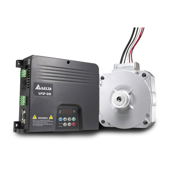
- Page 134 Appendix A Specifications |DD Series Motor Specifications Maximum speed: 240 RPM; Poles number: 8 pairs (16 poles) Frame ECMD-B9120GMS ECMD-B9160GMS Rated Output Power (W) Rated Voltage (V) Rated Torque (N-m) Rated Speed (rpm) Rated Current (A) 0.78 0.97 Continuous Stall Torque (N-m) Maximum Momentary Torque(N-m) Maximum Speed (rpm) Maximum Momentary Current (A)
-
Page 135: Appendix B How To Select Ac Motor Drive
Appendix B How to Select AC Motor Drive |DD Series Appendix B How to Select AC Motor Drive The choice of the right AC motor drive for the application is very important and has great influence on its lifetime. If the capacity of AC motor drive is too large, it cannot offer complete protection to the motor and motor maybe damaged. -
Page 136: Capacity Formula
Appendix B How to Select AC Motor Drive |DD Series B-1 Capacity Formulas 1. When one AC motor drive operates one motor The starting capacity should be less than 1.5x rated capacity of AC motor drive The starting capacity= ⎛ ⎞... - Page 137 Appendix B How to Select AC Motor Drive |DD Series Symbol explanation : Motor shaft output for load (kW) η : Motor efficiency (normally, approx. 0.85) cos φ : Motor power factor (normally, approx. 0.75) : Motor rated voltage(V) : Motor rated current(A), for commercial power : Correction factor calculated from current distortion factor (1.05 - 1.1, depending on PWM method) : Continuous motor capacity (kVA)
-
Page 138: General Precautions
Appendix B How to Select AC Motor Drive |DD Series B-2 General Precautions Drives Selection 1. When the AC Motor Drive is connected directly to a large-capacity power transformer (600kVA or above) or when a phase lead capacitor is switched, excess peak currents may occur in the power input circuit and the converter section may be damaged. -
Page 139: How To Choose A Suitable Motor
Appendix B How to Select AC Motor Drive |DD Series B-3 How to Choose a Suitable Motor Standard motor When using the AC Motor Drive to operate a standard 3-phase induction motor, take the following precautions: 1. The energy loss is greater than for an inverter duty motor. 2. - Page 140 Appendix B How to Select AC Motor Drive |DD Series Special motors: 1. Pole-changing (Dahlander) motor: The rated current is differs from that of a standard motor. Please check before operation and select the capacity of the AC motor drive carefully. When changing the pole number the motor needs to be stopped first.
- Page 141 Appendix B How to Select AC Motor Drive |DD Series Motor torque The torque characteristics of a motor operated by an AC motor drive and commercial mains power are different. Below you’ll find the torque-speed characteristics of a standard motor (4-pole, 15kW): AC motor drive Motor 60 seconds...