Table of Contents
Advertisement
Available languages
Available languages
Quick Links
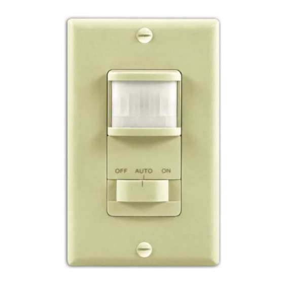
OFF
AUTO
ON
Included are:
• The sensor switch
• Cover plate
• 3 wire connectors
• 2 large screws
• 2 small screws.
INSTALLATION
SELECT A LOCATION
The sensor is more sensitive to motion across
the front of the sensor than to motion towards
the sensor.
The detector senses heat in motion and pos-
sibly heat sources that change temperature
quickly. Therefore, to avoid false triggering,
avoid placing the sensor where it will be aimed
at air conditioners, heaters, and other sources
of heat or cold.
© 2006 DESA Specialty Products™
Motion Sensor
Wall Switch
SL-6105
The SL-6105 Motion Sensor Wall Switch detects motion to turn on
lights for an adjustable amount of time. A built-in photo cell can be
set to keep lights off when the lights aren't needed. The unit has excel-
lent sensitivity and a wide 150° detection range. It can be used with
incandescent lighting as well as rapid start fluorescent lighting.
Installation is as easy as replacing a wall switch. However, some
codes require installation by a qualified electrician.
• 150° motion detection angle
• Adjustable on-time from 5 sec. to 20 min.
• Adjustable photocell
• Works with incandescent and rapid start
fluorescent lighting
• Works with motors up to 1/8 hp
• Slide switch selectable OFF, ON, and AUTO modes
15 ft. (4.6 m)
Features include:
30 ft.
(9.1 m)
Figure 1 - Typical Plan View of
Coverage
0
595-4881-10
Advertisement
Table of Contents

Related Manuals for Heath Zenith Motion Sensor Wall Switch SL-6105


Summary of Contents for Heath Zenith Motion Sensor Wall Switch SL-6105
- Page 1 AUTO Included are: • The sensor switch • Cover plate • 3 wire connectors • 2 large screws • 2 small screws. INSTALLATION SELECT A LOCATION The sensor is more sensitive to motion across the front of the sensor than to motion towards the sensor.
-
Page 2: Installing Sensor
WARNING: Turn power off at the circuit breaker before wiring. INSTALLING SENSOR Removing Control Panel Cover 1. Remove the decorative cover plate (secured by two small screws). 2. Press in with screwdriver as shown in Figure 2. Swing control panel cover out to remove. Control Panel Cover Figure 2 - Removing Control Panel Cover... -
Page 3: Completing Installation
AdJUSTMENTS Time There are 6 preset selections for the amount of time the lights stay on: Test (5 seconds), 1, 5, 10, 15, and 20 minutes. Use a small, phillips screw driver to adjust the TIME control (see Figure 4). Turn the TIME control until it “snaps”... -
Page 4: Troubleshooting
SYMPTOM POSSIBLE CAUSE 1. Circuit breaker or fuse is Light does turned off. not come 2. If the lamp being controlled has another switch, it may be turned off. 3. Bulb is defective. 4. LIGHT control is set too far toward the dark position. - Page 5 AUTO Se incluye: • interruptor del detector • Placa cubertora • 3 conectores de alambre • 2 tornillos grandes • 2 tornillos pequeños. INSTALACION ESCOJA UN LUGAR El detector es más sensitivo al movimiento que atraviesa por el frente que al que se dirige hacia el detector.
- Page 6 AdvERTENCIA: Apague la energía en el cortacircuitos antes de hacer las conexiones. INSTALACION dEL dETECTOR Cómo quitar la tapa del panel de control 1. Quite la placa cubertora decorativa (asegurada con dos tornillos decorativos). 2. Presione con un destornillador como se muestra en la Figura 2.
-
Page 7: Especificaciones
AJUSTES Tiempo Hay 6 ajustes precalibrados para el lapso de tiempo que las luces permanecen encendidas: Prueba (5 segundos), 1, 5, 10, 15 y 20 minutos. Use un destornillador Phillips pequeño para regular el control de TIEMPO (Vea la Figura 4). Gire el control hasta que se “coloque a presión”... -
Page 8: Guia De Solucion De Problemas
GUIA dE SOLUCION dE PROBLEMAS SINTOMA POSIBLE CAUSA 1. El cortacircuitos o el fusible está La luz no se apagado. prende 2. Si la lámpara que se controla tiene un interruptor, puede estar apagada. 3. La bombilla está mala. 4. El control de LUZ (LIGHT) está fijado muy cerca a la posición de OBSCURIDAD (DARK). 5. El selector de FASE (MODE) está en APAGADO (OFF) y no en AUTO(MATICO). 6. Está cableado incorrectamente. 1. El movimiento se ha parado en el La luz no cuarto. - Page 9 AUTO Éléments compris: • Interrupteur à détecteur • Plaque murale • 3 serre-fils • 2 grandes vis • 2 petites vis INSTALLATION dÉTERMINER L'EMPLACEMENT Le détecteur est plus sensible au mouvement transver- sal qu'au mouvement perpendiculaire au détecteur. Le détecteur perçoit la chaleur en mouvement et possiblement les sources de chaleur qui changent rapidement de température.
-
Page 10: Installation Du Détecteur
M I S E E N G A R d E : C o u p e r l'alimentation au disjoncteur avant de faire le câblage. INSTALLATION dU dÉTECTEUR Enlèvement du couvercle de la commande 1. Enlever la plaque décorative (fixée au moyen de deux vis). 2. - Page 11 RÉGLAGES Temps Il y a six périodes prédéfinies pour la durée de fonc- tionnement de l’éclairage : Test (5 secondes), 1, 5, 10, 15 et 20 minutes. Servez-vous d’un petit tournevis Phillips pour régler la commande TIME (voir la Figure 4). Faites tourner la commande TIME jusqu’à ce qu’elle s’enclenche à la position souhaitée. Intensité...
-
Page 12: Dépannage
SYMPTÔME CAUSE POSSIBLE 1. Le disjoncteur ou le fusible est hors L'éclairage circuit. ne s'allume pas. 2. Si la lampe commandée est raccordée à un autre interrupteur, celui-ci peut être en position hors circuit. 3. L'ampoule est brûlée. 4. La commande d'éclairage (LIGHT) est réglée trop loin vers la position sombre (DARK).
Need help?
Do you have a question about the Motion Sensor Wall Switch SL-6105 and is the answer not in the manual?
Questions and answers