
Related Manuals for ADDER CCS4-USB


Summary of Contents for ADDER CCS4-USB
- Page 1 CCS4-USB Four-port keyboard and mouse switch Free-Flow Now with switching technology ...
-
Page 2: Table Of Contents
Installing the standard configuration application ....16 What is True Emulation? .............4 Configuring a standard Free-Flow system ......16 CCS4-USB features - top and rear ..........5 Multi-Monitor Free-Flow configuration ......17 What’s in the box ................6 Installing drivers and multi-monitor config app ....17 What you may additionally need ..........6... -
Page 3: Introduction
The video displays are connected directly to their respective systems as usual. A single USB link (plus an optional speaker connection) is made between each system and the CCS4-USB switch. compact unit created to allow a single operator to access information and control operations across numerous systems and screens. -
Page 4: What Is Free-Flow
(e.g side-by-side, vertical stack, square formation, etc.). You then download this information to the CCS4-USB switch and this is used during operation to determine the precise moment to switch from one screen/system to the next. -
Page 5: What Is True Emulation
What is True Emulation? True Emulation represents a significant breakthrough in sharing USB devices True Emulation between two or more computer systems. Until this point, the problem has been Mindful of the limitations associated with the OTHER USB how to create a USB switch that provides all of the following: previous USB switching techniques, we set about KEYBOARD MOUSE... -
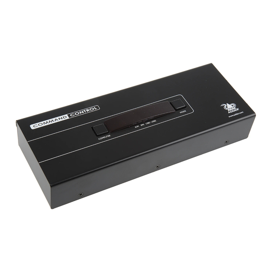
Page 6: Ccs4-Usb Features - Top And Rear
CCS4-USB features - top and rear The CCS4-USB switch is housed within durable, metallic enclosure with all connectors situated at the rear panel. The smart top panel features the control buttons and the operation indicators. COMPUTER SPK USB1 USB2 MODE www.adder.com... -
Page 7: What's In The Box
What’s in the box CCS4-USB switch Four self-adhesive Power adapter (12.5W) and rubber feet country-specific power lead Flash upgrade cable Part number: VSC40 What you may additionally need Optional CCS-XB LED monitor indicator kit USB cable 2m (type A to B) Audio cable 2m (3.5mm stereo jacks) -
Page 8: Installation
CCS4-USB switch: advisable to mount the CCS4-USB switch in place, either: • Situate the CCS4-USB switch close to the systems to which it will be • On a horizontal surface using the supplied self adhesive feet, or connected and near to a source of mains power. -
Page 9: Connections
From speakers T IO Computer systems From USB keyboard and mouse Each computer system is connected to the CCS4-USB switch using (up to) two cables. To connect a computer system 3 USB devices: Where required, attach the leads from 1 Ensure that power is disconnected from the CCS4-USB switch and the your USB peripherals to the USB sockets labelled system to be connected. -
Page 10: Power Connection
Power connection The CCS4-USB switch is supplied with a 12.5W power adapter. There is no on/ off switch on the switch, so operation begins as soon as a power adapter is connected. To connect the power supply 1 Attach the output lead from the power... -
Page 11: Optional Rc4 Remote Control
1 Connect either end of the supplied cable to the socket at the rear of the RC4 remote control. To connect the remote control to the CCS-XB module 1 Once you have used the Adder FreeFlow utility to program the CCS4-USB switch (see the section Configuring LED monitor... -
Page 12: Optional Led Monitor Indicator Connections
2 Link each LED monitor indicator to a port on the CCS-XB indicators to each of your video display screens to show which are active. module - ports 1 to 4 are most commonly used. Note: The CCS4-USB switch requires firmware version 2.0 or later to be installed. Please see here for details about how to check. -
Page 13: Checking The Ccs4-Usb Firmware Version
1.02 and requires an upgrade. 3 Press E and then press Enter to return the CCS4-USB to normal operation. If your CCS4-USB unit does require a firmware upgrade, please refer to the Performing upgrades... -
Page 14: Switching Control By Computer
You can use either the supplied flash upgrade cable (part number VSC40) or alternatively construct a custom cable to link the CCS4-USB switch and the computer. For pin-out details of the custom cable, see... -
Page 15: Configuration
( ) section. 38400 The configuration mode allows you to determine numerous aspects of the 57600 CCS4-USB switch capabilities. 115200 Enter the Functions menu Show current firmware version Reset configuration to factory defaults ( is displayed momentarily) Enter the Hotkey menu... -
Page 16: General Configuration
General configuration Changing hotkeys Miscellaneous functions CCS4-USB switches use as their standard hotkeys. These can be To reset configuration to factory defaults changed if they clash with other software or hardware within the installation. 1 Enter the Configuration menu. 2 Press... -
Page 17: Free-Flow Configuration
LED monitor indicator: 1 Install the application onto any computer (not necessarily one of the four computers linked to the CCS4-USB switch) that has a vacant serial port. Run the installation application and follow the on-screen instructions. -
Page 18: Multi-Monitor Free-Flow Configuration
Choose the required components and click the Next > button. 3 Once the chosen components have been installed, click the Finish button. Note: On the PC that will be used to set up the CCS4-USB switch, you can optionally tick ‘Click to run the Free-Flow Configuration Application’ in the... -
Page 19: Configuring Multiple Monitors
The important thing is to define where each screen edge abuts to the next to the CCS4-USB port. If the optional CCS-XB module is connected OPTIONS so that the CCS4-USB switch can determine the correct moments to switch to the port, then instead connect the upgrade cable between the OPTIONS channels. -
Page 20: Configuring Led Monitor Indicators
6 Click OK to save and exit. 7 Repeat steps 1 to 6 for each screen that requires an LED monitor indicator. 8 Choose Configure > Send Layout to Switch to update the CCS4-USB switch. 9 IMPORTANT: Once the Free-Flow configuration application has downloaded the setup, remove and reconnect power to the CCS4-USB to allow the new settings to take effect. -
Page 21: Additional Free-Flow Operations And Settings
Enable (Disable) Free-Flow Acceleration This option allows you to switch off the Free-Flow feature within the CCS4-USB Mouse acceleration allows you to move the mouse pointer quickly across the switch. Located within Configure > Switch... menu item, untick the Enable... -
Page 22: Performing Upgrades
6 - Query the CCS4-USB switch Click the Query Unit button to confirm that communication is possible with the CCS4-USB switch and to establish its firmware details. If successful, the 2 .5 ‘Unit connected’ field should show the name of the CCS4-USB switch and the current firmware will also be listed. - Page 23 WARNING: Running faulty or partially upgraded code may have unpredictable IMPORTANT: Check that the ‘Intended Target Units’ field matches the results and may damage your CCS4-USB switch or computing equipment. ‘Unit Connected’ field. If these fields do not match then you may have an incorrect upgrade file, check with Adder Technology Ltd before proceeding.
-
Page 24: Operation
You can continue to use any of the other channel switching methods while Will switch only USB peripheral 2 Free-Flow is enabled. Notes: The four upper indicators on the CCS4-USB display panel will scroll across every few seconds to show that Free-Flow is enabled. See What is Free-Flow? for an... -
Page 25: To Select A Computer Using Hotkeys
‘hotkeys’ and to choose Cycle only active ports they signal to the CCS4-USB switch that you wish to control it, rather than 3 Press to accept the setting and return to the main menu section. -
Page 26: To Select A Computer Using The Mouse Buttons
To select a computer using the mouse buttons Using the mouse buttons, you can quickly switch the keyboard and mouse, speakers and/or USB peripherals to any computer channel. Note: These procedures work only with three-button or IntelliMouse devices and only if the ‘Mouse Switching’ option has been enabled. To select a computer using the mouse buttons 1 Hold down the middle button (or scroll wheel) of the mouse. -
Page 27: To Lock Access To The Computers
To lock access to the computers When privacy is required, you can lock access to the connected computers via the switch. To lock the switch 1 Simultaneously press and hold (or other hotkeys, if altered). 2 While still holding , press The display will show (providing a valid password has been previously set). -
Page 28: Further Information
Use our forum to access FAQs and discussions. • Technical support – www.adder.com/contact-support-form For technical support, use the contact form in the Support section of the adder.com website - your regional office will then get in contact with you. -
Page 29: Appendix 1 - Cable Pin-Outs
Appendix 1 – Cable pin-outs port uses a 10p10c socket which can accommodate both 10p10c OPTIONS connectors as well as the much more common 8p8c connectors, which are used on Ethernet leads and patch cables. The pin-outs are listed in this section for both types of connector. -
Page 30: Safety Information
If the product should fail to operate correctly in normal use during the flammable materials. warranty period, Adder will replace or repair it free of charge. No liability can be • Warning – the power adapter contains live parts. -
Page 31: Radio Frequency Energy
Radio Frequency Energy All interface cables used with this equipment must be shielded in order to maintain compliance with radio frequency energy emission regulations and ensure a suitably high level of immunity to electromagnetic disturbances. European EMC directive 2004/108/EC FCC Compliance Statement (United States) This equipment has been tested and found to comply with the limits for a class This equipment generates, uses and can radiate radio frequency energy A computing device in accordance with the specifications in the European... - Page 32 Web: www.adder.com www.adder.com/contact-details Contact: Support: forum.adder.com © 2013 Adder Technology Limited All trademarks are acknowledged. Documentation by: www.ctxd.com Part No. MAN-CCS4-USB-ADDER • Release 2.9h...
Need help?
Do you have a question about the CCS4-USB and is the answer not in the manual?
Questions and answers