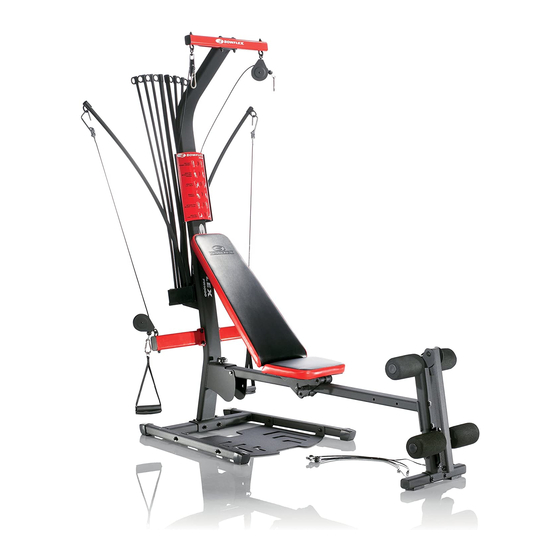
Bowflex PR1000 Assembly Manual
Home gym
Hide thumbs
Also See for PR1000:
- Quick start manual ,
- Assembly and owner's manual (48 pages) ,
- Owner's manual (36 pages)

Subscribe to Our Youtube Channel
Related Manuals for Bowflex PR1000


Summary of Contents for Bowflex PR1000
-
Page 1: Assembly Manual
® ® PR1000 Home Gym Assembly Manual Nautilus Bowflex Schwinn Fitness Universal ® ® ® ® 001-7276.101512.E... -
Page 2: Table Of Contents
Before Assembly Select where you are going to locate your Bowflex® home gym carefully. The best location is on a hard, level surface. For best results, assemble your home gym in the location where you intend to use it. For safe operation, allow a workout area of at least 127”... -
Page 3: Important Safety Instructions
Important Safety Instructions This icon means a potentially hazardous situation which, if not avoided, could result in death or serious injury. Obey the following warnings: Read and understand all warnings on this machine. Carefully read and understand the Assembly Manual. •... -
Page 4: Hardware
Hardware (Hardware not actual size) Qty. 4 Qty. 5 Item #1 Item #8 5/16”x 3/4” Hex Head 1/4” Washer Bolt Qty. 8 Qty. 4 Item #2 Item #9 3/8”x 3/4” Hex Head 5/16” Washer Bolt Qty. 2 Qty. 29 Item #3 Item #10 3/8”x 2 3/4”... -
Page 5: Parts
Parts Assembly Manual... - Page 6 Upper Lat Tower Manual Kit Sliding Seat End Caps Lower Lat Tower Clips Threaded Knob Chest Pulley Cross Bar Seat Slider Seat Rail with Slider Leg Press Belt Leg Extension Rubber Pad Leg Extension Base Cable Clip Bowflex® Rod Pack Assembly Manual...
-
Page 7: Assembly
Assembly Step 1: Attach the Lower Lat Tower to the Base Parts • Base Platform (#17) • Lower Lat Tower (#21) Hardware • (2) 3/8” x 3/4” Hex Head Bolts (#2) • (2) 3/8” Washers (#10) Tools • Adjustable Wrench (not included) 1-1 Attach the Lower Lat Tower to the Base Platform with first set of bolts. -
Page 8: Secure The Lower Lat Tower To The Base
Assembly Step 2: Secure the Upper Lat Tower to the Base Parts • Completed Assembly (from step 1) Hardware • (2) 3/8” x 4” Hex Head Bolts (#5) • (4) 3/8” Washers (#10) • (2) 3/8”Nuts (#11) Tools • (2) Adjustable Wrenches (not included) 2-1 Install the second set of bolts and tighten all of the hardware. -
Page 9: Assemble The Seat Rail
Assembly Step 3: Assemble the Seat Rail Parts • Seat Rail (#23) • Seat Cushion (#20) • Seat Slider (#36) Hardware • (4) 5/16” x 3/4” Hex Head Bolts (#1) • (4) 5/16” Washers (#9) • (1) Rubber Pad (#38) Tools •... -
Page 10: Assemble The Leg Extension
Assembly Step 4: Assemble the Leg Extension Parts • Leg Extension (#24) • Leg Extension Cross Tube (#25) Hardware • (2) 3/8” x 3” Hex Head Bolt (#4) • (4) 3/8” Washers (#10) • (2) 3/8” Nut (#11) Tools • (2) Adjustable Wrenches (not included) 4-1 Set the bracket end of the Leg Extension onto the Leg Extension Tube and align the bolt holes. -
Page 11: Attach The Seat Rail To The Leg Extension
Assembly Step 5: Attach the Seat Rail to the Leg Extension Parts • Seat Rail Assembly (from step 3) • Leg Extension Assembly (from step 4) Hardware • (2) 3/8” x 2 3/4” Hex Head Bolt (#3) • (3) 3/8” Washers (#10) •... -
Page 12: Attach The Seat Rail To The Base Assembly
Assembly Step 6: Attach the Seat Rail to the Base Assembly Parts • Seat Rail Assembly (from step 5) • Completed Assembly (from step 2) Hardware • (1) 3/8” x 4 1/4” Hex Head Bolt (#12) • (2) 3/8” Washers (#10) •... -
Page 13: Upper Lat Tower
Assembly Step 7: Upper Lat Tower Parts • Upper Lat Tower • Lat Tower Cross Bar with Pulleys and Cables Hardware • (2) 3/8” x 3” Hex Head Bolt (#4) • (4) 3/8” Washers (#10) • (2) 3/8” Nut (#11) Tools •... -
Page 14: Attach The Upper Lat Tower To The Base Assembly
Assembly Step 8: Attach the Upper Lat Tower to the Base Assembly Parts • Upper Lat Tower Assembly (from step 7) • Completed Assembly (from step 6) Hardware • (6) 3/8” x 3/4” Hex Head Bolt (#2) • (6) 3/8” Washers (#10) Tools •... -
Page 15: Apply The Cable Clip
Assembly Step 9: Apply the Cable Clip Parts • (1) Cable Clip (#39) • Completed Assembly (from step 8) 9-1 Apply the Cable Clip to the rear of the Lower Lat Tower. Note: Be sure to use the cable clip when the cables are not in use. 6”... -
Page 16: Attach The Rod Pack
Assembly Step 10: Attach the Rod Pack Parts • Completed Assembly (from step 9) • (1) Bowflex® Rod Pack (#26) • (1) Rod Box End Plate (#31) Hardware • (3) #10 x 1” Self Tapping Screws (#7) • (2) 1/4” x 1” Phillips Head Bolt (#13) •... -
Page 17: Chest Bar With Pulleys
Assembly Step 11: Chest Bar with Pulleys Parts • Completed Assembly (from step 10) • Chest Bar with Pulleys and Cables (#22) Hardware • (2) 3/8” x 5” Hex Head Bolts (#6) • (4) 3/8” Washers (#10) • (2) 3/8” Nuts (#11) Tools •... -
Page 18: Leg Extension Rollers
Assembly Step 12: Leg Extension Rollers Parts • (4) Foam Roller Pads (#27) • (4) Tube End Plugs (#33) • (1) Long Roller Tube (#29) • (1) Short Roller Tube (#28) • Completed Assembly (from step 11) 12-1 Insert the Roller Tubes through the Leg Extension. 12-2 Slide the Foam Rollers onto the Roller Tubes. -
Page 19: Attach The Bench
Assembly Step 13: Attach the Bench Parts • Bench Cushion (#16) • Completed Assembly (from step 12) 13-1 Put the Bench Cushion onto the Seat Rail and the Seat Slider. Assembly Manual... -
Page 20: Attach Placard
Assembly Step 14: Attach Placard Parts • Exercise Placard (#30) • Completed Assembly (from step 13) 14-1 Snap the Excercise Placard onto the upper Lat Tower. Assembly Manual... -
Page 21: Level The Machine
Assembly Step 15: Level the Machine Parts • Completed Assembly (from step 14) Tools • (2) Adjustable Wrenches (not included) 15-1 Loosen but do not remove the bolts on the foot plate. 15-2 Stand on the foot plate until it rests flat on the floor. 15-3 Re-tighten the bolts. -
Page 22: Connect The Cables To The Powerrod® Unit, Chest Bar, And Handgrips
Assembly Step A: Connect the Cables to the Power Rod® Unit, Chest Bar, and Handgrips Parts • (2) Handgrips (#15) A-1 Remove the plastic and unwrap the cables from the Chest Bar Pulleys. A-2 Attach the Rod Hooks to the Power Rod® Unit. A-3 Connect the Handgrips to the Snap Hooks on the Cables. -
Page 23: Connect The Cables From The Chest Bar And Lat Cross Bar To The Handgrips
Assembly Step B: Connect the Cables from the Chest Bar and Lat Cross Bar to the Handgrips Parts • (2) Handgrips (#15) B-1 Remove the plastic and unwrap the cables from the Lat Bar Pulleys. B-2 Attach the Snap Hooks from the Chest Bar Pulleys to the Cables on the Lat Cross Bar. B-3 Attach the Handgrips to the Snap Hooks from the Lat Cross Bar. -
Page 24: Connect The Cables From The Chest Bar To The Leg Extension
Assembly Step C: Connect the Cables from the Chest Bar to the Leg Extension C-1 Remove the plastic and unwrap the cables from the Leg Extension Pulleys. C-2 Attach the Snap Hooks from the Chest Bar Pulleys to the Leg Extension Cables. Final Inspection Inspect your machine to ensure that all fasteners are tight and components are properly assembled. - Page 25 Assembly Manual...
- Page 26 Assembly Manual...
- Page 27 Assembly Manual...
-
Page 28: Contacts
Nautilus, Inc., (800) NAUTILUS / (800) 628-8458, www.NautilusInc.com - Customer Service: North America (800) 605-3369, csnls@nautilus.com | outside U.S. +01-360-859- 5180, technics-APLA@nautilus.com | Printed in China | © 2008 Nautilus, Inc. Nautilus Bowflex Schwinn Fitness Universal ® ® ® ®...
Need help?
Do you have a question about the PR1000 and is the answer not in the manual?
Questions and answers