
Subscribe to Our Youtube Channel
Related Manuals for Bowflex Sport 001-6961


Summary of Contents for Bowflex Sport 001-6961
-
Page 1: Assembly Instructions
����� The Bowflex Sport ® Home Gym Assembly Instructions ��������������� 001-6961 Rev B (06-19-06) -
Page 2: Table Of Contents
Safety Precautions Get to Know Your Machine Basic Assembly Principles Parts List Hardware List Accessory List Hardware Guide Tools You Will Need Assembly Guide Important Contact Numbers Table of Contents... -
Page 3: Safety Precautions
Never use dumbbells or other weight equipment to incrementally increase the weight resistance. Use only the Power Rods® that came with your Bowflex Sport ® home gym. Set up and use your Bowflex Sport ® home gym • on a hard, level surface. •... -
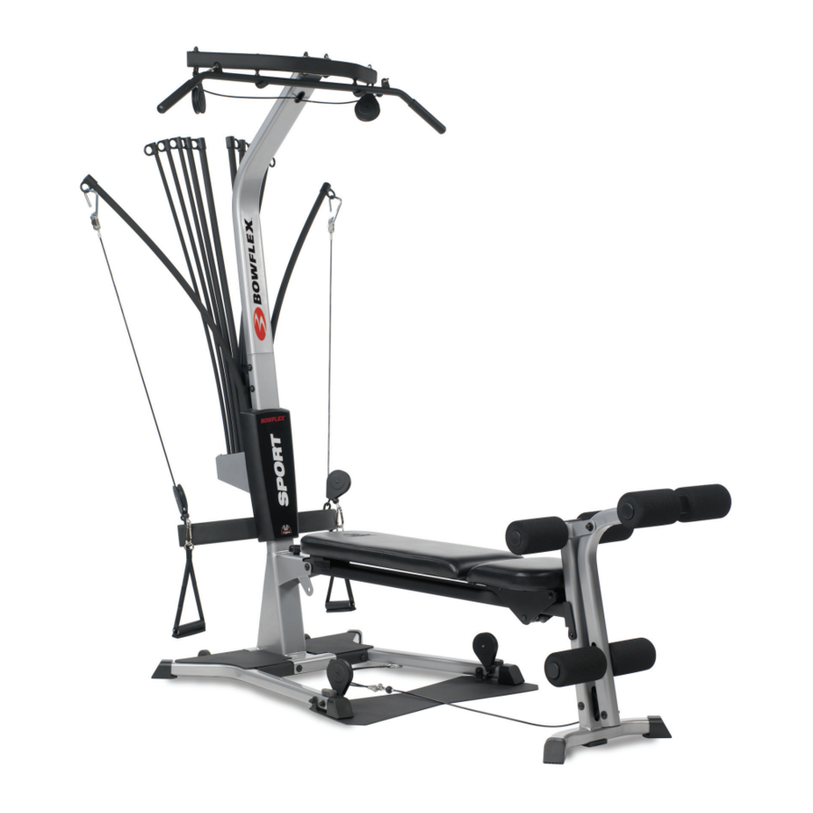
Page 4: Get To Know Your Machine
CONGRATULATIONS on your commitment to improving your health and fitness! With the Bowflex Sport ® home gym, you have everything you need to exceed all of your physical fitness, strength and health expectations! The Bowflex Sport ® home gym’s exceptional resistance and quality is unmatched by any other single piece of home fitness equipment available. -
Page 5: Basic Assembly Principles
3. When attaching two pieces, gently lift and look through the bolt holes to help guide the bolt through the holes. 4. As a general rule, and for all bolts and nuts on your Bowflex Sport® home gym, turn bolts or nuts toward the right to tighten and left to loosen. -
Page 6: Hardware Guide
Tools You Will Need You will need the following tools to complete the assembly of your Bowflex Sport® home gym. If you don’t have these tools, you can find them at any hardware or department store for a reasonable price. - Page 7 Step 1 - Attach the Lower Lat Tower to the Base Platform Locate the following items: • Item #1 - Lower Lat Tower • Item #2 - Base Platform • Item #H - (4) 3/8" X 3" Button Head Screws •...
- Page 8 Step 3 - Attach the Squat Platform to the Main Assembly Locate the following items: • From Step 2 - Base Platform/Lat Tower (Main) Assembly • Item #5 - Squat Platform • Item #I - (2) 3/8" X 3 1/4" Button Head Screws •...
-
Page 9: Main Assembly
Step 4 - Attach the Chest Bar with Pulleys to the Main Assembly Locate the following items: • From Step 3 - Main Assembly • Item #6 - Chest Bar w/ Pulleys - Do not unwrap cables! • Item #K - (2) 3/8" X 5" Button Head Screws •... - Page 10 Step 6 - Attach the Seat Rail to the Seat Assembly Locate the following items: • From Step 5 - Seat Pad/Seat Bracket Assembly • Item #9 - Seat Rail Undo the twist ties from the Rail Pivot Bushings and remove the Bushings.
- Page 11 Step 8 - Attach the Rear Leg to the Seat Rail Figure 8 Locate the following items: • From Step 6 - Seat Rail Assembly • From Step 7 - Rear Leg Assembly • Item #J - (1) 3/8" X 4 1/4" Button Head Screw •...
- Page 12 Step 9 - Attach the Seat Rail to the Main Assembly Figure 9 Locate the following items: • From Step 4 - Main Assembly Main Assembly • From Step 8 - Seat Rail Assembly • Item #12 - Seat Rail Knob •...
- Page 13 Step 10 - Attach the Leg Extension Pivot Tube Locate the following items: • Item #13 - Leg Extension Pivot Tube • From Step 9 - Main Assembly • Item #30 - Lock Out Pin • Item #G - (1) 3/8" X 2 3/4" Button Head Screw •...
- Page 14 Assembly Guide Figure 12...
- Page 15 Assembly Guide Figure 13 Step 13 - Assemble the Leg Extension Seat Locate the following items: • Item #19 - Leg Extension Seat Pad • Item #21 - Leg Extension Seat Support Tube • Item #C - (4) 5/16" X 3/4" Button Head Screws •...
- Page 16 Step 14 - Attach the Leg Extension Seat to the Main Assembly Locate the following items: • From Step 13 - Leg Extension Seat Assembly • From Step 12 - Main Assembly The Leg Extension Seat Assembly is removable, and can be attached to the Rear Leg Assembly easily by placing the Rail Bracket Hooks over the Rear Rollers.
- Page 17 Step 16 - Attach the Upper Lat Tower to the Lower Locate the following items: • From Step 15 - Upper Lat Tower Assembly • From Step 14 - Main Assembly • Item #E - (6) 3/8" X 3/4" Button Head Screw •...
- Page 18 Figure 19...
- Page 19 Figure 20...
- Page 20 Bench, lift up on the long portion and pull away from Seat. Steps 23 through 26 illustrate how to route and connect the Cables to your new Bowflex Sport® Home Gym. Step 23 - Route the Rod Cables Locate the following items: •...
-
Page 21: Route Lat/Squat Cables
Figure 26 - Squat Cables... -
Page 22: Important Contact Numbers
IMPORTANT CONTACT NUMBERS If you need assistance, please have both the serial number of your machine and the date of purchase available when you contact the appropriate Nautilus office listed below. OFFICES IN THE UNITED STATES: E-mail: cstech@nautilus.com • NAUTILUS INNOVATION CENTER Nautilus, Inc. - Page 24 1-800-605-3369 for assistance. ©2004 Nautilus Inc. All rights reserved. 1400 N.E. 136th Ave., Vancouver, WA 98684. Bowflex, Bowflex Sport, Power Rod and the Bowflex and Nautilus logos are either registered trademarks or trademarks of Nautilus, Inc.
Need help?
Do you have a question about the Sport 001-6961 and is the answer not in the manual?
Questions and answers