Sun Microsystems Ultra Enterprise 450 Owner's Manual
Ultra enterprise 450 server
Hide thumbs
Also See for Ultra Enterprise 450:
- Product notes (80 pages) ,
- Installation manual (42 pages) ,
- Upgrade manual (24 pages)
Table of Contents
Troubleshooting

Related Manuals for Sun Microsystems Ultra Enterprise 450


Summary of Contents for Sun Microsystems Ultra Enterprise 450
- Page 1 Ultra Enterprise 450 Server ™ ™ Owner’s Guide Sun Microsystems Computer Company A Sun Microsystems, Inc. Business 2550 Garcia Avenue Mountain View, CA 94043 USA 415 960-1300 fax 415 969-9131 Part No.: 805-0429-10 Revision A, July 1997...
- Page 2 Sun Microsystems, Inc. The OPEN LOOK and Sun™ Graphical User Interface was developed by Sun Microsystems, Inc. for its users and licensees. Sun acknowledges the pioneering efforts of Xerox in researching and developing the concept of visual or graphical user interfaces for the computer industry. Sun holds a non-exclusive license from Xerox to the Xerox Graphical User Interface, which license also covers Sun’s licensees who implement OPEN...
-
Page 3: Regulatory Compliance Statements
FCC radio frequency emission limits. Networking connections can be made using unshielded twisted-pair (UTP) cables. Modifications: Any modifications made to this device that are not approved by Sun Microsystems, Inc. may void the authority granted to the user by the FCC to operate this equipment. - Page 4 This Class B digital apparatus meets all requirements of the Canadian Interference-Causing Equipment Regulations. Cet appareil numérique de la classe B respecte toutes les exigences du Règlement sur le matériel brouilleur du Canada. Ultra Enterprise 450 Server Owner’s Guide • July 1997...
-
Page 5: Declaration Of Conformity
Declaration of Conformity Compliance ID: Product Name: Ultra Enterprise 450, Ultra 450 Creator, and Ultra 450 Creator3D families USA – FCC Class B This equipment complies with Part 15 of the FCC Rules. Operation is subject to the following two conditions: 1. - Page 6 15-amp power outlet (North America only). See “How to Determine System Power Requirements” on page 82 for additional information. Ultra Enterprise 450 Server Owner’s Guide • July 1997...
-
Page 7: Table Of Contents
About the Status and Control Panel 8 System Setup 11 About the Parts Shipped to You 12 How to Install the Ultra Enterprise 450 Server 13 How to Install the Rear Panel Security Device 17 About Setting Up a Console 20 How to Attach an Alphanumeric Terminal 21 How to Configure a Local Graphics Console 23... - Page 8 How to Determine System Power Requirements 82 Parts Installation and Repair 97 About Handling Boards 100 How to Install the 8-Bay Storage Expansion Option 101 Main Logic Board Components 112 viii Ultra Enterprise 450 Server Owner’s Guide • July 1997...
- Page 9 How to Remove the Main Logic Board 113 How to Install the Main Logic Board 116 How to Remove a Memory Module 120 How to Install a Memory Module 123 How to Remove a CPU Module 126 How to Install a CPU Module 128 How to Remove a DC/DC Converter 130 How to Install a DC/DC Converter 132 How to Remove a PCI Card 134...
- Page 10 How to Remove the Removable Media SCSI Cable 256 How to Install the Removable Media SCSI Cable 259 How to Remove a SCSI Drive Power Cable 262 How to Install a SCSI Drive Power Cable 265 Ultra Enterprise 450 Server Owner’s Guide • July 1997...
- Page 11 How to Remove the SCSI Drive Data Cable 267 How to Install the SCSI Drive Data Cable 270 How to Remove the 4-Slot UltraSCSI Power Cable 274 How to Install the 4-Slot UltraSCSI Power Cable 276 How to Remove the 4-Slot UltraSCSI Data Cable 278 How to Install the 4-Slot UltraSCSI Data Cable 284 How to Remove an 8-Slot UltraSCSI Power Cable 290 How to Install an 8-Slot UltraSCSI Power Cable 292...
- Page 12 Diagnostics and Troubleshooting 369 About Diagnostic Tools 370 About Power-On Self-Test (POST) Diagnostics 372 How to Use POST Diagnostics 373 About OpenBoot Diagnostics (OBDiag) 375 How to Use OpenBoot Diagnostics (OBDiag) 383 Ultra Enterprise 450 Server Owner’s Guide • July 1997...
- Page 13 How to Set the Diagnostic Level for POST and OBDiag 386 About SunVTS Software 387 How to Check Whether SunVTS Software Is Installed 389 How to Use SunVTS Software 390 About Solstice SyMON Software 392 About Troubleshooting Your System 393 About Diagnosing Specific Problems 403 A.
- Page 14 Ultra Enterprise 450 Server Owner’s Guide • July 1997...
-
Page 15: Preface
Preface Ultra Enterprise 450 Server Owner’s Guide answers your questions about setting up and running the Ultra™ Enterprise™ 450 server. Features and options, installation, troubleshooting, parts replacement, and network administration information for the Ultra Enterprise 450 server are covered in this manual. - Page 16 The following table shows the default system prompt and superuser prompt for the C shell, Bourne shell, and Korn shell. Shell Prompt C shell machine_name% C shell superuser machine_name# Bourne shell and Korn shell Bourne shell and Korn shell superuser Ultra Enterprise 450 Server Owner’s Guide • July 1997...
- Page 17 Conventions The following table describes the typographic conventions used in this book. Typeface or Symbol Meaning Examples The names of commands, files, Edit your .login file. AaBbCc123 and directories; on-screen Use ls -a to list all files. computer output. % You have mail. What you type, when AaBbCc123 contrasted with on-screen...
-
Page 18: Related Documents
Caution – Improper handling by unqualified personnel can cause serious damage to this equipment. Unqualified personnel who tamper with this equipment may be held liable for any resultant damage to the equipment. xviii Ultra Enterprise 450 Server Owner’s Guide • July 1997... - Page 19 Some procedures in this document must be performed by trained maintenance providers. Only people who have been trained at the Sun Microsystems™ training facilities (or by Sun Microsystems affiliates) and have been certified as required by local and national laws are considered qualified.
-
Page 20: Sun Welcomes Your Comments
If a card is not available, you can email or fax your comments to us. Please include the document part number in the subject line of your message. Email: smcc-docs@sun.com Fax: SMCC Document Feedback, 1-415-786-6443 Ultra Enterprise 450 Server Owner’s Guide • July 1997... -
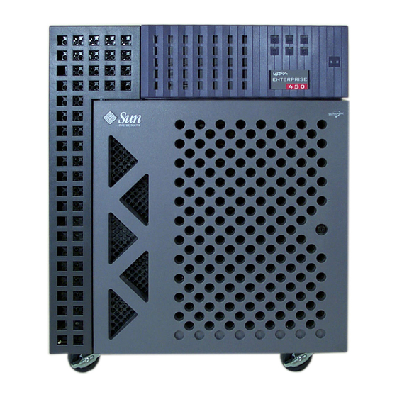
Page 21: System Overview
C H A P T E R System Overview This chapter introduces you to the Ultra Enterprise 450 server and explains some of its features. Information covered in this chapter includes: About the Ultra Enterprise 450 Server—page 2 Locating Front Panel Features—page 5 Locating Rear Panel Features—page 7... -
Page 22: About The Ultra Enterprise 450 Server
About the Ultra Enterprise 450 Server The Ultra Enterprise 450 server is a high-performance, shared memory, symmetric- multiprocessing server system. It is designed around Sun’s high-speed Ultra Port Architecture (UPA) cross-bar system interconnect and Sun’s UltraSPARC processors to deliver outstanding overall system performance. - Page 23 SCSI port provided on the system’s rear panel. Additional external tape devices can be supported with appropriate PCI host adapter cards. The Ultra Enterprise 450 server can easily be connected to either a 10-Mbps or a 100-Mbps Ethernet by means of an auto-sensing Ethernet interface provided on the system’s main logic board.
- Page 24 Power system monitoring and fault protection N+1 power supply redundancy Hot swap power supplies with easy rear access Automatic system recovery Four levels of system diagnostics Easy side access to all internal replaceable components Ultra Enterprise 450 Server Owner’s Guide • July 1997...
-
Page 25: Locating Front Panel Features
Locating Front Panel Features The illustration below shows the system features that are accessible from the front panel with the top and bottom doors open. Status and control panel Tape drive slot CD-ROM drive slot Diskette drive slot Top door Bottom door Internal disk bays... - Page 26 When the key is in the vertical position, the door is unlocked. Make sure that the key is in this position before you close the door. To lock the door, simply turn the key 90 degrees clockwise and remove the key. Unlocked Locked Ultra Enterprise 450 Server Owner’s Guide • July 1997...
-
Page 27: Locating Rear Panel Features
Locating Rear Panel Features The illustration below shows the system features that are accessible from the rear panel. Power inlet AC power switch SCSI Serial port A/B Parallel port Keyboard / mouse TPE Ethernet MII Ethernet PCI slots 1-10 Power supplies Power supply LEDs Power supplies and the main AC power switch are accessible from the system rear panel. -
Page 28: About The Status And Control Panel
The LEDs consist of two types: system health indicators and fault indicators. The system health indicators light to show you that the system is functioning normally. The fault indicators light when a problem is detected in the system. Because it is Ultra Enterprise 450 Server Owner’s Guide • July 1997... - Page 29 important for you to know that a fault exists in the system, the fault indicators remain lit when the system is reset or switched to standby mode using the keyswitch. When the system is first powered on, the LEDs are individually toggled on and off to verify that each one is working correctly.
- Page 30 To power off the system completely, use the AC power switch located on the rear panel. See “How to Power Off the System” on page 26. Ultra Enterprise 450 Server Owner’s Guide • July 1997...
-
Page 31: System Setup
Tasks covered in this chapter include: How to Install the Ultra Enterprise 450 Server—page 13 How to Install the Rear Panel Security Device—page 17 How to Attach an Alphanumeric Terminal—page 21 How to Configure a Local Graphics Console—page 23... -
Page 32: About The Parts Shipped To You
Save the original shipping containers and packing materials in case you need to store or ship your system. If you cannot store the shipping materials, recycle or dispose of the materials properly. Consult your local recycling authority for information. Ultra Enterprise 450 Server Owner’s Guide • July 1997... -
Page 33: How To Install The Ultra Enterprise 450 Server
Server Before You Begin The Ultra Enterprise 450 server is a general-purpose server, which you can use for many types of applications. Exactly how you set up your machine depends in some measure upon what you want it to do. - Page 34 How to Install a Disk Drive—page 186 How to Install a CD-ROM Drive or Tape Drive—page 192 How to Install a Power Supply—page 226 How to Install the 8-Bay Storage Expansion Option—page 101 Ultra Enterprise 450 Server Owner’s Guide • July 1997...
- Page 35 Caution – If you are installing an internal option in your system, you must ensure that it does not cause your configuration to exceed the system power supply limits; see “How to Determine System Power Requirements” on page 82 for additional information.
- Page 36 See the appropriate documents provided in the server media kit for a complete listing of included software and detailed installation instructions. 12. Load the Ultra Enterprise 450 server AnswerBook™ online documentation and ShowMe™ How™ multimedia documentation. See the installation booklets that accompany these CD-ROM discs in the Ultra Enterprise 450 server documentation set.
-
Page 37: How To Install The Rear Panel Security Device
How to Install the Rear Panel Security Device The rear panel security device supplied with the system is designed to prevent unauthorized removal of the system power supplies, main logic board, and left side panel. What to Do 1. Attach the small security bracket to the rear of the system chassis as shown below. The bracket comes with a captive Phillips screw. - Page 38 Use the captive Phillips screw at the top of the bracket. 5. Install a padlock or combination lock through the bracket to prevent unauthorized removal of the system power supplies and main logic board. Ultra Enterprise 450 Server Owner’s Guide • July 1997...
- Page 39 6. Attach the remaining security bracket to the bottom corner of the rear panel as shown below. The bracket comes with a captive Phillips screw. Remove the existing screw from the system chassis first. 7. Install a padlock or combination lock through the bracket to prevent unauthorized removal of the left side panel.
-
Page 40: About Setting Up A Console
PCI slot, and attach a monitor, mouse, and keyboard to the appropriate back panel ports. For detailed instructions, see “How to Configure a Local Graphics Console” on page 23. Ultra Enterprise 450 Server Owner’s Guide • July 1997... -
Page 41: How To Attach An Alphanumeric Terminal
How to Attach an Alphanumeric Terminal Before You Begin If your server is configured without a local graphics console, you need to attach an alphanumeric terminal (or establish a tip connection) to the server in order to install the system and to run diagnostic tests. For background information, see “About Setting Up a Console”... - Page 42 3. Set the terminal to receive: At 9600 baud An 8-bit signal with no parity and 1 stop bit See the documentation accompanying your terminal for more information. Ultra Enterprise 450 Server Owner’s Guide • July 1997...
-
Page 43: How To Configure A Local Graphics Console
How to Configure a Local Graphics Console Before You Begin If your server is configured without a local graphics console, you need to install one in order to install the system and to run diagnostic tests. For background information, see “About Setting Up a Console” on page 20. Alternatively, you can attach an ASCII terminal (or modem line) to the system’s serial port;... -
Page 44: What Next
5. Attach the mouse cable to the appropriate receptacle on the keyboard. What Next You can now issue system commands and view system messages. Continue with your installation or diagnostic procedure as needed. Ultra Enterprise 450 Server Owner’s Guide • July 1997... -
Page 45: Preparing To Install Or Replace Parts
C H A P T E R Preparing to Install or Replace Parts This chapter tells you what you need to know, and need to do, before opening the system to install, remove, or replace parts. Tasks covered in this chapter include: How to Power Off the System—page 26 How to Power On the System—page 28 How to Initiate a Reconfiguration Boot—page 30... -
Page 46: How To Power Off The System
4. Wait for the system halt messages and the ok prompt. 5. Turn the keyswitch on the front panel of the system to the Standby position ( which is fully counterclockwise. Standby position Ultra Enterprise 450 Server Owner’s Guide • July 1997... - Page 47 6. Press the AC power switch on the system rear panel to turn off power. Chapter 3 Preparing to Install or Replace Parts...
-
Page 48: How To Power On The System
A terminal or monitor is required for viewing system messages. For setup instructions, see “How to Configure a Local Graphics Console” on page 23. 3. Open the top door on the front of the system. Ultra Enterprise 450 Server Owner’s Guide • July 1997... - Page 49 4. Turn the keyswitch to the Standby position ( Standby position 5. Press the rear panel AC power switch to the On ( ) position. 6. Turn the keyswitch to the appropriate setting. See “About the Status and Control Panel” on page 8 for information about keyswitch settings.
-
Page 50: How To Initiate A Reconfiguration Boot
After a device has been added to a device tree, it can be recognized by the system. After the reconfiguration reboot has successfully completed, the system prompt should be displayed. Ultra Enterprise 450 Server Owner’s Guide • July 1997... - Page 51 Note – The system may take anywhere from 30 seconds to two minutes before video is displayed on the system monitor or the ok prompt appears on an attached terminal. This time depends on the level of power-on self-test diagnostics being performed.
-
Page 52: How To Remove The Right Side Panel
“How to Power Off the System” on page 26 What to Do 1. Loosen the two large captive screws that secure the right side panel to the rear of the system chassis. Ultra Enterprise 450 Server Owner’s Guide • July 1997... - Page 53 2. Slide the panel toward the rear of the system approximately 1 inch (2.5 cm). The hooks beneath the top surface of the panel should disengage from the slots on top of the system chassis. 3. Lift the panel up and free from the system chassis. Put the panel in a safe location until you’re ready to reassemble the system.
-
Page 54: How To Install The Right Side Panel
2. Press the lower edge flush against the chassis and slide the panel toward the front of the unit as far as it will go. Ultra Enterprise 450 Server Owner’s Guide • July 1997... - Page 55 3. Tighten the two large captive screws that secure the panel to the rear of the system chassis. What Next When you’re ready to restart the system, see: “How to Power On the System” on page 28; or “How to Initiate a Reconfiguration Boot” on page 30 Chapter 3 Preparing to Install or Replace Parts...
-
Page 56: How To Remove The Left Side Panel
“How to Power Off the System” on page 26 What to Do 1. Loosen the two large captive screws that secure the left side panel to the rear of the system chassis. Ultra Enterprise 450 Server Owner’s Guide • July 1997... - Page 57 2. Slide the panel toward the rear of the system approximately 1 inch (2.5 cm). The hooks beneath the top surface of the panel should disengage from the slots on top of the system chassis. 3. Lift the panel up and free from the system chassis. Put the panel in a safe location until you’re ready to reassemble the system.
-
Page 58: How To Install The Left Side Panel
2. Press the lower edge flush against the chassis and slide the panel toward the front of the unit as far as it will go. Ultra Enterprise 450 Server Owner’s Guide • July 1997... - Page 59 3. Tighten the two large captive screws that secure the panel to the rear of the system chassis. What Next When you’re ready to restart the system, see: “How to Power On the System” on page 28 “How to Initiate a Reconfiguration Boot” on page 30 Chapter 3 Preparing to Install or Replace Parts...
-
Page 60: How To Avoid Electrostatic Discharge
The only time you should unplug the cord is when you service the AC line filter assembly or power distribution board. Ultra Enterprise 450 Server Owner’s Guide • July 1997... - Page 61 2. Use an antistatic mat or similar surface. When performing any option installation or service procedure, place static-sensitive parts, such as boards, cards, and disk drives, on an antistatic surface. The following items can be used as an antistatic surface: The bag used to wrap a Sun™...
-
Page 62: Reference For Installation And Service: Tools Required
Grounding wrist or foot strap The latter two items help protect the server against damage due to electrostatic discharge. For more information, see “How to Avoid Electrostatic Discharge” on page 40. Ultra Enterprise 450 Server Owner’s Guide • July 1997... -
Page 63: Hardware Configuration
C H A P T E R Hardware Configuration This chapter describes hardware configurations for the system. Topics covered in this chapter include: About Reliability, Availability, and Serviceability Features—page 44 About Memory—page 51 About CPU Modules—page 54 About DC/DC Converters—page 56 About Peripheral Component Interconnect (PCI) Buses—page 58 About Internal Disk Drives—page 61 About Power Supplies—page 64... -
Page 64: About Reliability, Availability, And Serviceability Features
In addition to providing ECC protection for data, the system offers parity protection on all system address buses. Parity protection is also used on the PCI and SCSI buses, and in the UltraSPARC CPU’s internal and external cache. Ultra Enterprise 450 Server Owner’s Guide • July 1997... -
Page 65: Status Leds
Status LEDS The system provides easily accessible light emitting diode (LED) indicators on the system front panel, internal disk bays, and power supplies to provide a visual indication of system and component status. Status LEDs eliminate guesswork and simplify problem diagnosis for enhanced serviceability. Status and control panel LEDs are described in “About the Status and Control Panel”... -
Page 66: Environmental Monitoring And Control
If the operating system fails to reset the timer within three minutes, the system automatically accelerates all fans to full speed. The fans spinning at full speed also provide an audible warning that the system is not functioning properly. Ultra Enterprise 450 Server Owner’s Guide • July 1997... - Page 67 The monitoring subsystem is also designed to detect and respond to fan failures. The system includes seven fans, arranged into three groups as follows: CPU fan tray assembly (three fans) Disk fan tray assembly (three fans) Upper blower assembly (one fan) A fan failure in the CPU or disk fan tray assemblies causes the monitoring subsystem to generate an error message, light the temperature LED on the status and control panel, and shut down the system.
- Page 68 Control over the system’s ASR functionality is provided by a number of OpenBoot PROM commands. These are described in the document Platform Notes: Sun Ultra 450 Workstation and Ultra Enterprise 450 Server, available on the Solaris on Sun Hardware AnswerBook. This AnswerBook documentation is provided on the SMCC Updates CD for the Solaris release you are running.
-
Page 69: Hardware Watchdog Mechanism
Solaris on Sun Hardware AnswerBook. Hardware Watchdog Mechanism To detect and respond to system hang conditions, the Ultra Enterprise 450 server features a hardware watchdog mechanism—a hardware timer that is continually reset as long as the operating system is running. In the event of a system hang, the operating system is no longer able to reset the timer. - Page 70 It allows you to monitor system hardware status and operating system performance of your server. For more information about SyMON, see “About Solstice SyMON Software” on page 392. Ultra Enterprise 450 Server Owner’s Guide • July 1997...
-
Page 71: About Memory
About Memory The system’s main logic board provides sixteen slots for high-capacity dual inline memory modules (DIMMs). The system supports Sun standard 144-pin, 5-volt, 60-nanosecond memory modules. Modules of 16-, 32-, 64-, 128-, and 256-Mbyte capacities can be installed in the system. Total system memory capacity ranges from 64 Mbytes to 4 Gbytes. - Page 72 Platform Notes: Sun Ultra 450 Workstation and Ultra Enterprise 450 Server, available on the Solaris on Sun Hardware AnswerBook. This AnswerBook documentation is provided on the SMCC Updates CD for the Solaris release you are running. Note – In some cases, Platform Notes: Sun Ultra 450 Workstation and Ultra Enterprise 450 Server may be included with your system documentation instead of on the Solaris on Sun Hardware AnswerBook.
- Page 73 For maximum performance, install identical capacity DIMMs in all four memory banks. The following table shows how to best populate the memory banks when configuring your system for 512 Mbytes of memory. Memory Performance Level Memory Slot Population Good Bank A has four, 128-MB DIMMs (no interleaving) Better Banks A and B each have four 64-MB DIMMs (two-way interleaving) Best...
-
Page 74: About Cpu Modules
All CPUs installed in a system must operate at identical clock speeds. Fill the CPU slots in the following order: Order of Installation Slot Number Slot Name Connector Number First CPU-B2 J0401 Second CPU-A2 J0201 Third CPU-B1 J0301 Last CPU-A1 J0101 Ultra Enterprise 450 Server Owner’s Guide • July 1997... - Page 75 For each CPU module installed in the system, you must install an associated DC/DC converter. If the DC/DC converter is not installed or is installed in the wrong location, the system will not operate. For information on DC/DC converter, see “About DC/DC Converters”...
-
Page 76: About Dc/Dc Converters
For information about installing a DC/DC converter, see “How to Install a DC/DC Converter” on page 132. For more information about CPU modules, see “About CPU Modules” on page 54 and “How to Install a CPU Module” on page 128. Ultra Enterprise 450 Server Owner’s Guide • July 1997... - Page 77 The following figure shows the CPU slot and DC/DC converter socket locations on the main logic board. CPU-A1 J0101 CPU Slot 1 CPU-A2 J0201 CPU Slot 2 CPU-B1 J0301 CPU Slot 3 CPU-B2 J0401 CPU Slot 4 DC-B1 DC-A1 DC-B2 DC-A2 DC/DC converters Chapter 4...
-
Page 78: About Peripheral Component Interconnect (Pci) Buses
Most PCI cards operate at clock speeds of 33 MHz, while some newer cards operate at 66 MHz. The system will accept up to three cards that operate at 66 MHz and up to ten cards that operate at 33 MHz. Ultra Enterprise 450 Server Owner’s Guide • July 1997... - Page 79 The table below shows the mapping of the PCI slots to the three PCI-UPA bridges and six PCI buses, and the type of PCI cards supported in each slot. PCI-UPA Slot Width (bits)/ Clock Rates DC Voltage/ Slot Bridge Card Type (bits) (MHz) Card Type 32 / 32 only...
- Page 80 PCI bus B, which supports slot 10, already supports both the onboard UltraSCSI controller for four internal disk drives plus the onboard FastEthernet. Additional high-throughput interfaces may perform better when installed on another bus. Ultra Enterprise 450 Server Owner’s Guide • July 1997...
-
Page 81: About Internal Disk Drives
About Internal Disk Drives The Ultra Enterprise 450 server supports up to 4, 12, or 20 internal, hot-pluggable UltraSCSI disk drives. Drives are 3.5-inches wide by 1-inch high. Four drives are supported by the 40-Mbyte per second UltraSCSI interface on the system’s main logic board. - Page 82 It is also possible to determine both the disk slot number and the logical device name if you know the physical device name (such as /devices/ pci@6,4000/scsi@4,1/sd@3,0). Physical device names are typically provided in SCSI error messages generated by software. Ultra Enterprise 450 Server Owner’s Guide • July 1997...
- Page 83 For instructions on how to translate from one form of disk identifier to another, see Platform Notes: Sun Ultra 450 Workstation and Ultra Enterprise 450 Server. Configuration Rules Disk drives must be Sun standard 3.5-inches wide by 1-inch high, UltraSCSI-compatible drives.
-
Page 84: About Power Supplies
In a system with three power supplies, the third power supply is always redundant; it cannot be used to increase output capacity. Ultra Enterprise 450 Server Owner’s Guide • July 1997... - Page 85 Power supplies in a redundant configuration feature a “hot swap” capability. You can remove and replace a faulty power supply without turning off the system power or even shutting down the operating system. In order to determine how many power supplies are required to provide redundancy for your configuration, you must calculate the power requirements for your system.
-
Page 86: About The Standard Ethernet Port
Ethernet wiring types. When an external transceiver is connected to the MII, the system automatically activates the MII port and disables the TPE port. Sun Microsystems offers an MII-to-AUI transceiver as a separately orderable option (order number X467A). A number of third-party MII transceivers are also available for connecting to TX, T4, FX, and AUI-type Ethernet networks. -
Page 87: About The Serial Ports
About the Serial Ports The system provides two serial communications ports through a single, shared DB-25 connector located on the rear panel. The primary port is capable of both synchronous and asynchronous communication, while the secondary port is asynchronous only. In synchronous mode, the primary port operates at any rate from 50 Kbaud to 256 Kbaud when the clock is generated internally. -
Page 88: About The Parallel Port
EPP protocol modes as well as standard Centronics, Nibble, and Byte modes. See “Reference for the Parallel Connector” on page 416 for the connector diagram, rear panel icon, and pin assignments. Ultra Enterprise 450 Server Owner’s Guide • July 1997... -
Page 89: About The Main Logic Board Jumpers
About the Main Logic Board Jumpers The jumpers on the main logic board have the following functions: J3303 and J3304 are used to configure the serial ports provided for either EIA-423 or EIA-232D operation. For information about the EIA-423/232D jumper settings, see “About Serial Port Jumpers”... - Page 90 Pin 1 is marked with an asterisk (*) in any of the positions shown below. J 3 X X X Part number Pins Asterisk indicates Pin 1 Shaded region indicates default jumper position Ultra Enterprise 450 Server Owner’s Guide • July 1997...
-
Page 91: About Serial Port Jumpers
About Serial Port Jumpers The serial port jumpers on the main logic board (J3303 and J3304) permit the configuration of the system’s two serial ports for either EIA-423 or EIA-232D signal levels. EIA-423 levels are the default standard for North American users. EIA-232D levels are required for digital telecommunication in nations of the European Community. -
Page 92: About The Clock Mode Select Jumper
Jumper Pins 1 + 2 Select Pins 2 + 3 Select on Pins Signal Controlled J2701 Correct clock Not used 1 + 2 UPA_RATIO2 mode for any UltraSPARC II CPU modules Ultra Enterprise 450 Server Owner’s Guide • July 1997... -
Page 93: About Flash Prom Jumpers
About Flash PROM Jumpers The system uses flash PROMs to permit the reprogramming of specific code blocks that are held in non-volatile system memory, and to permit remote reprogramming of that code by an authorized system administrator over a local area network. Three jumpers on the main logic board affect flash PROM operation. - Page 94 Power-on position ( ) or to the Diagnostics position ( the flash PROM is write-enabled. For more information about flash PROM programming, see the documentation supplied with the flash PROM update CD-ROM. Ultra Enterprise 450 Server Owner’s Guide • July 1997...
-
Page 95: About The Scsi Removable Media Bays And The External Scsi Port
About the SCSI Removable Media Bays and the External SCSI Port The removable media assembly located at the top front of the system provides mounting bays for two SCSI devices. The lower bay houses a SCSI 12x CD-ROM drive. The upper bay is a 5.25-inch half-height (1.6-inch) bay, which may be used for a narrow SCSI (50-pin) tape drive, such as an 8-mm tape, a 4-mm DDS-2 or DDS-3 tape, or a quarter-inch cassette tape drive. -
Page 96: Bus Length
Note – If you connect a narrow device to the external SCSI port, the on-board terminators only disable the termination for the lower byte of data; the upper byte is still terminated on the main logic board. Ultra Enterprise 450 Server Owner’s Guide • July 1997... - Page 97 Use the following cabling guidelines to ensure proper device termination: The SCSI bus must be correctly terminated. Most Sun devices use autotermination. See the documentation supplied with the device. If all external mass storage devices use 68-pin connectors, connect all non-Sun devices to the system first and Sun devices last in the chain, since Sun 68-pin devices use autotermination.
- Page 98 If external mass storage devices consist of 68-pin devices and 50-pin devices, connect the Sun 68-pin devices to the system first and terminate the chain with a 50-pin device and its terminator. Ultra Enterprise 450 Server Owner’s Guide • July 1997...
-
Page 99: About Power Budget Constraints
About Power Budget Constraints You must ensure that your configuration does not exceed the power budget constraints of the system. This section describes the following three areas in which system power budget constraints occur: Maximum rated values for the +3.3, +5, and +12 VDC power supply outputs Total power supply output capacity Current limit of the AC power outlet “How to Determine System Power Requirements”... - Page 100 If the configuration exceeds the safety threshold for power supply operation, then the system shuts itself off automatically. See “About the Status and Control Panel” on page 8 for information about the general fault indicator. Ultra Enterprise 450 Server Owner’s Guide • July 1997...
- Page 101 Total AC Current Draw Using your value for total watts required by the system, you can calculate the total AC current draw by the system. You must ensure that the AC current draw does not exceed the maximum current limit for the 15-Amp power outlet. In the United States and Canada, the maximum is 80 percent of the outlet’s total capacity, which is 12 A.
-
Page 102: How To Determine System Power Requirements
In this case, you should calculate the +3.3 V and +5 V total (Step 8 in the following procedure) with the information you have available. The number you obtain will not be Ultra Enterprise 450 Server Owner’s Guide • July 1997... - Page 103 completely accurate, but it should still allow you to judge if your system is going to exceed the limit. Then, when you calculate the total DC watts (Step 10 in the following procedure), you must remember to include the total watts for the option. It is not unusual for the information supplied with PCI cards to only provide the total watts required for the card.
- Page 104 If you have two supplies, is the value in Line 5 less than 800 W? If yes, proceed to Step 10. If no, proceed to “What to Do If Your System Exceeds Power Supply Capacity” on page 92. Ultra Enterprise 450 Server Owner’s Guide • July 1997...
- Page 105 10. Add together the three numbers in Line 4 and record the sum in Line 6. This is the total DC watts required by your system configuration. Remember that you must add in the numbers for options for which you only have the total watts. See the following example.
- Page 106 1. The base system value includes a chassis with seven fans, the main logic board, LED interface board, power distribution board, and disk backplanes. (It does NOT include CPU modules, memory modules, or internal storage devices; values for those options must be entered separately.) Ultra Enterprise 450 Server Owner’s Guide • July 1997...
- Page 107 +3.3 Total Total Total Line Amps @ +5 VDC Amps @ Amps @ Option Amps 3.3 V Amps Amps 12 V SunCD 4 Internal CD-ROM 1.44 MB diskette drive (pk) PCI Cards Dual single-ended UltraSCSI disk controller 15 W PCI card 25 W PCI card Miscellaneous MII-to-AUI transceiver...
- Page 108 Total must not exceed 560 watts (per supply). 1. The first value is for a system with one power supply; the second is for a system with two or three power supplies. Ultra Enterprise 450 Server Owner’s Guide • July 1997...
- Page 109 Sample Calculation of DC Watts The following sample power budget is for a system that is configured with these options: Two 250 MHz CPU modules Eight 32 MB DIMMs Twelve 4.2 GB hard disk drives One 4mm DDS-3 tape drive One SunCD 12 CD-ROM drive One diskette drive Two dual single-ended UltraSCSI disk controllers...
- Page 110 2.5 GB QIC tape drive SunCD 12 CD-ROM SunCD 4 Internal CD-ROM 1.44 MB diskette drive (pk) PCI Cards Dual single-ended UltraSCSI disk controller 15 W PCI card 25 W PCI card Ultra Enterprise 450 Server Owner’s Guide • July 1997...
- Page 111 +3.3 Total Total Total Line Amps @ +5 VDC Amps @ Amps @ Option Amps 3.3 V Amps Amps 12 V Miscellaneous MII-to-AUI transceiver Third Party Options DC Amp Maximum Rating 47/94 65/130 16/36 DC Amp Total Per Output 20.9 32.3 14.8 Multiply this number with...
- Page 112 (See “About the Status and Control Panel” on page 8 for information about the general fault indicator.) Ultra Enterprise 450 Server Owner’s Guide • July 1997...
- Page 113 How to Calculate Your AC Power Requirements You must ensure that the AC current draw does not exceed the maximum current limit for a 15-Amp power outlet. In the United States and Canada, the maximum is 80 percent of the outlet’s total capacity, which is 12 A. For areas outside of the United States and Canada, contact local agencies for local electrical codes about specific information on local AC branch limitations.
- Page 114 6. Calculate the Volt-Amps for your configuration as follows: ------ - true Where: is the result of Step 1 true is the reciprocal of the power factor ------ - PF = 0.98 (typical) Ultra Enterprise 450 Server Owner’s Guide • July 1997...
- Page 115 Sample Calculation of Total AC Amps The following calculations are based on the configuration described on page 89. DC watts ------------- true ---------- 408.1 true 0.68 600.15 true true AC amps --------------------------------- - AC volts PF 600.15 AC amps ------------------------- - 120 0.98 AC amps 5.10...
- Page 116 If you exceed the 12 A current limit, then you must remove as many configuration items as required to lower the AC current draw of your configuration to an acceptable level. Ultra Enterprise 450 Server Owner’s Guide • July 1997...
-
Page 117: Parts Installation And Repair
C H A P T E R Parts Installation and Repair This chapter describes how to remove and install components within the system. For a list of part numbers for field-replaceable units and optional equipment, see “Illustrated Parts Breakdown” on page 438. Note –... - Page 118 How to Install a SCSI Drive Power Cable—page 265 How to Remove the SCSI Drive Data Cable—page 267 How to Install the SCSI Drive Data Cable—page 270 How to Remove the 4-Slot UltraSCSI Power Cable—page 274 Ultra Enterprise 450 Server Owner’s Guide • July 1997...
- Page 119 How to Install the 4-Slot UltraSCSI Power Cable—page 276 How to Remove the 4-Slot UltraSCSI Data Cable—page 278 How to Install the 4-Slot UltraSCSI Data Cable—page 284 How to Remove an 8-Slot UltraSCSI Power Cable—page 290 How to Install an 8-Slot UltraSCSI Power Cable—page 292 How to Remove an 8-Slot UltraSCSI Data Cable—page 294 How to Install an 8-Slot UltraSCSI Data Cable—page 297 How to Remove the LED Interface Cable—page 301...
-
Page 120: About Handling Boards
Board connectors and components have very thin pins that bend easily. Do not use an oscilloscope probe on the components. The soldered pins are easily damaged or shorted by the probe point. Transport the board in an antistatic bag. Ultra Enterprise 450 Server Owner’s Guide • July 1997... -
Page 121: How To Install The 8-Bay Storage Expansion Option
How to Install the 8-Bay Storage Expansion Option Caution – If you are installing this part as an option, you must ensure that it does not make your configuration exceed the system power budget; see “How to Determine System Power Requirements” on page 82 for more information. Caution –... -
Page 122: Before You Begin
1. Remove the filler panel for the PCI slot you intend to use. a. Remove the Phillips screw that secures the PCI filler panel to the rear panel. b. Pull out the filler panel. Ultra Enterprise 450 Server Owner’s Guide • July 1997... - Page 123 2. Insert the PCI card into the appropriate slot on the main logic board. a. Align the left side of the card with the appropriate opening on the rear panel. b. Push the card into the corresponding slot on the main logic board. 3.
- Page 124 7. Connect the I C cable. If you are installing the lower 8-slot backplane, connect the I C cable between connector P0500 on the 4-slot backplane and connector P0600 on the 8-slot backplane. Ultra Enterprise 450 Server Owner’s Guide • July 1997...
- Page 125 If you are installing the upper 8-slot backplane, connect the I C cable between connector P0601 on the lower 8-slot backplane and connector P0600 on the upper 8-slot backplane. Chapter 5 Parts Installation and Repair...
- Page 126 If you are installing the upper 8-slot backplane, use connector J0304 on the power distribution board. Be sure that the tab on the right side of the connector snaps into place. Ultra Enterprise 450 Server Owner’s Guide • July 1997...
- Page 127 10. Remove the three small Phillips screws that secure the cable access panel to the top of the system chassis. 11. Tilt the front edge of the access panel upward and lift it free from the chassis. Chapter 5 Parts Installation and Repair...
- Page 128 15. If the 8-slot UltraSCSI data cable has excess slack, carefully fold the cable and secure the fold using the cable clip attached to the CPU card cage. Do not crease the cable when you fold it. Ultra Enterprise 450 Server Owner’s Guide • July 1997...
- Page 129 16. Connect the other end of the cable to the 8-slot backplane. Connect P1-B to the upper connector, J0402, and connect P1-A to the lower connector, J0102. If you are installing two expansion option kits, the UltraSCSI data cable on the outside (on top in the access port) must connect to the lower 8-slot backplane.
- Page 130 2. When the system banner is displayed on the monitor, immediately enter the Stop-a sequence on the Sun keyboard. If you are using an alphanumeric terminal instead of a monitor, press the Break key on the terminal’s keyboard. Ultra Enterprise 450 Server Owner’s Guide • July 1997...
- Page 131 3. When the ok prompt is displayed, enter the following command: ok setenv disk-led-assoc 0 x y where: x is an integer between 1 and 10 identifying the PCI slot number where the lower UltraSCSI controller is installed y is an integer between 1 and 10 identifying the PCI slot number where the upper UltraSCSI controller is installed For example, if the controller cards are installed in PCI slots 5 and 7, enter the following:...
-
Page 132: Main Logic Board Components
How to Install a DC/DC Converter—page 132 How to Remove a PCI Card—page 134 How to Install a PCI Card—page 136 How to Remove the NVRAM Module—page 139 How to Install the NVRAM Module—page 141 Ultra Enterprise 450 Server Owner’s Guide • July 1997... -
Page 133: How To Remove The Main Logic Board
How to Remove the Main Logic Board Caution – This procedure must be performed by a qualified service-trained maintenance provider. Persons who remove any of the outer panels to access this equipment must observe all safety precautions and comply with skill level requirements, certification, and all applicable local and national laws. - Page 134 3. Loosen the five large captive screws that secure the main logic board to the rear of the chassis. 4. Remove the main logic board. Carefully slide the board all the way out of the chassis, using the handles at the rear of the board. Ultra Enterprise 450 Server Owner’s Guide • July 1997...
- Page 135 Caution – If you have not removed all CPU modules, take care that the CPU ejection levers do not catch on the chassis. 5. Place the main logic board on an antistatic mat. What Next To replace the main logic board, complete this task: “How to Install the Main Logic Board”...
-
Page 136: How To Install The Main Logic Board
After you remove the panels, the PCI section of the replacement board and the defective board should look the same. a. Remove the Phillips screw that secures the filler panel to the replacement board. Ultra Enterprise 450 Server Owner’s Guide • July 1997... - Page 137 b. Remove the PCI filler panel. Keep the filler panel and screw for possible future use. 2. Set the jumpers on the replacement main logic board so that they are the same as the settings on the old board. See “About the Main Logic Board Jumpers” on page 69 for more information about jumper locations and settings.
- Page 138 The upper blower power cable, at connector J4705 c. The 4-slot UltraSCSI data cable, at connector J5601 6. If you disconnected 8-slot UltraSCSI data cables from their UltraSCSI controller cards, reconnect them. Ultra Enterprise 450 Server Owner’s Guide • July 1997...
- Page 139 What Next Remove the NVRAM module from the replacement board and install it on the old board for return to Sun. See “How to Install the NVRAM Module” on page 141. Complete these tasks to transfer the components that you removed from the old main logic board to the new board: “How to Install the NVRAM Module”...
-
Page 140: How To Remove A Memory Module
Handle the modules only by their edges. Do not touch the components or any metal parts. Always wear a grounding strap when you handle the modules. Ultra Enterprise 450 Server Owner’s Guide • July 1997... - Page 141 What to Do 1. Locate on the main logic board the memory module that you want to remove. The sockets are arranged in four banks, as shown in the illustration. U1901 through U1904 - bank A U1801 through U1804 - bank B U1701 through U1704 - bank C U1601 through U1604 - bank D Memory banks...
- Page 142 3. Grasp both corners of the memory module and pull it out of the socket. Place the memory module on an antistatic mat. What Next To replace the memory module, complete this task: “How to Install a Memory Module” on page 123 Ultra Enterprise 450 Server Owner’s Guide • July 1997...
-
Page 143: How To Install A Memory Module
How to Install a Memory Module Caution – If you are installing this part as an option, you must ensure that it does not make your configuration exceed the system power budget; see “How to Determine System Power Requirements” on page 82 for more information. Before You Begin Caution –... - Page 144 Note – Each bank used must contain four modules of equal capacity (for example, four 32-Mbyte memory modules, four 64-Mbyte modules) to function properly. Do not mix capacities in any bank. Memory banks Memory banks Ultra Enterprise 450 Server Owner’s Guide • July 1997...
- Page 145 3. Align the memory module with its socket so that the small notch on the corner of the module is on the same side as the lever. 4. Hold the bottom edge of the module parallel to its socket. Carefully align the module so that each of its gold edge contacts is centered on a socket pin.
-
Page 146: How To Remove A Cpu Module
2. Lift the ejection levers away from the CPU module to release it from the CPU cage. The ejection levers are located on each side of the CPU module. Using both thumbs, push the levers away from the CPU module. Ultra Enterprise 450 Server Owner’s Guide • July 1997... - Page 147 3. Pull evenly on the corners of the CPU module and slide it all the way out of the CPU cage. 4. Place the CPU module on an antistatic mat. What Next To replace a CPU module, complete this task: “How to Install a CPU Module”...
-
Page 148: How To Install A Cpu Module
3. Slide the CPU module evenly into the CPU slot on the main logic board. Push on both sides of the CPU module until it is firmly seated in the slot. 4. Hook each ejection lever onto its side of the CPU cage. Ultra Enterprise 450 Server Owner’s Guide • July 1997... - Page 149 5. Push the ejection levers toward the center of the module. What Next Make sure that the CPU modules and DC/DC converter modules are installed in the correct locations. For additional information, see: “About DC/DC Converters” on page 56 “About CPU Modules” on page 54 Complete the following tasks to reassemble the system: “How to Install the Left Side Panel”...
-
Page 150: How To Remove A Dc/Dc Converter
1. Push up the holding clips that secure the DC/DC converter module in place. The clips are located on each side of the module. Push up the clip on one side first, then the other. Ultra Enterprise 450 Server Owner’s Guide • July 1997... - Page 151 2. Pull the DC/DC converter module all the way out of the slot. Grab the metal plate on each side and pull out the converter. 3. Place the DC/DC converter on an antistatic mat. What Next To replace a DC/DC converter module, complete this task: “How to Install a DC/DC Converter”...
-
Page 152: How To Install A Dc/Dc Converter
DC/DC converter modules must be installed in specific locations corresponding to the CPU module locations. For additional information, see: “About DC/DC Converters” on page 56 What to Do 1. Locate the socket into which you will install the DC/DC converter. Ultra Enterprise 450 Server Owner’s Guide • July 1997... - Page 153 2. Push the DC/DC converter into the socket. When the converter is properly seated, the two white holding clips will automatically close to secure it. What Next Make sure that the DC/DC converter modules and CPU modules are installed in the correct locations.
-
Page 154: How To Remove A Pci Card
3. Remove the Phillips screw that secures the faceplate of the PCI card to the rear panel of the system. Use a magnetized screwdriver, if possible, to prevent the screw from falling into the system chassis. Ultra Enterprise 450 Server Owner’s Guide • July 1997... - Page 155 4. Pull the PCI card all the way out of the slot. Hold the PCI card by the edges. 5. Place the PCI card on an antistatic mat. 6. If you are not replacing the PCI card immediately, install a PCI filler panel. Secure the filler panel with the screw from the PCI card faceplate.
-
Page 156: How To Install A Pci Card
Insert the left side of the PCI card into the appropriate opening on the rear panel. At the same time, insert the right side of the card into the corresponding groove on the CPU cage. Ultra Enterprise 450 Server Owner’s Guide • July 1997... - Page 157 b. Push the card into the slot on the main logic board. To install a PCI short card, a. Align the left side of the card with the appropriate opening on the rear panel. Chapter 5 Parts Installation and Repair...
- Page 158 “How to Install the Left Side Panel” on page 38 If you installed the PCI card as a new option, complete this task: “How to Initiate a Reconfiguration Boot” on page 30 Ultra Enterprise 450 Server Owner’s Guide • July 1997...
-
Page 159: How To Remove The Nvram Module
How to Remove the NVRAM Module Caution – This procedure must be performed by a qualified service-trained maintenance provider. Persons who remove any of the outer panels to access this equipment must observe all safety precautions and comply with skill level requirements, certification, and all applicable local and national laws. - Page 160 3. Place the NVRAM module on an antistatic mat. What Next To replace the NVRAM module, complete this task: “How to Install the NVRAM Module” on page 141 Ultra Enterprise 450 Server Owner’s Guide • July 1997...
-
Page 161: How To Install The Nvram Module
How to Install the NVRAM Module Caution – This procedure must be performed by a qualified service-trained maintenance provider. Persons who remove any of the outer panels to access this equipment must observe all safety precautions and comply with skill level requirements, certification, and all applicable local and national laws. - Page 162 “How to Install the Left Side Panel” on page 38 Note – If you are installing a new NVRAM module, the NVRAM must be reprogrammed by a Sun authorized service representative before your system can resume normal operation. Ultra Enterprise 450 Server Owner’s Guide • July 1997...
-
Page 163: Backplanes
Backplanes This section describes how to remove and install system backplanes. For a list of part numbers, see “Illustrated Parts Breakdown” on page 438. Tasks covered in this section include: How to Remove the Power Distribution Board—page 144 How to Install the Power Distribution Board—page 151 How to Remove the Removable Media Backplane—page 157 How to Install the Removable Media Backplane—page 161 How to Remove the 4-Slot UltraSCSI Backplane—page 165... -
Page 164: How To Remove The Power Distribution Board
“How to Remove the Disk Fan Tray Assembly” on page 210 What to Do 1. Unplug the AC power cord from the back of the system. The power cord must be unplugged when you are handling the power distribution board. Ultra Enterprise 450 Server Owner’s Guide • July 1997... - Page 165 2. Unplug all cables that are connected to the power distribution board, except the flat cables at connectors J0201 and J0202. Press the tab on the side of the cable connectors to release the connector. J0308 J0302 J0303 J0304 J0305 J0306 J0307 a.
- Page 166 Disconnect the removable media SCSI cable, at connector J4701. c. Disconnect the upper blower power cable, at connector J4705. d. Disconnect the 4-slot UltraSCSI data cable, at connector J5601. e. Disconnect any internal PCI cables. Ultra Enterprise 450 Server Owner’s Guide • July 1997...
- Page 167 5. Pull the main logic board approximately 6 inches (15 cm) out of the system. a. Loosen the five screws on the rear panel. b. Carefully slide the main logic board part way out of the chassis, using the handles at the rear of the board. 6.
- Page 168 Remove the screws that secure the guide to the bottom of the chassis. The guide holds the disk fan tray. You need to remove it from the chassis before you can remove the power distribution board. Ultra Enterprise 450 Server Owner’s Guide • July 1997...
- Page 169 9. Remove the eight Phillips screws that secure the power distribution board to the chassis center divider wall. Use a magnetized screwdriver, if possible, to prevent the screws from falling into the system chassis. 10. Remove the power distribution board from the chassis center divider wall. a.
- Page 170 Place the board on an antistatic mat. What Next To replace the power distribution board, complete this task: “How to Install the Power Distribution Board” on page 151 Ultra Enterprise 450 Server Owner’s Guide • July 1997...
-
Page 171: How To Install The Power Distribution Board
How to Install the Power Distribution Board Caution – This procedure must be performed by a qualified service-trained maintenance provider. Persons who remove any of the outer panels to access this equipment must observe all safety precautions and comply with skill level requirements, certification, and all applicable local and national laws. - Page 172 5. Bend the blue flat cables from the power distribution board flat against the divider wall. This prevents the cables from interfering with the installation of the main logic board. Ultra Enterprise 450 Server Owner’s Guide • July 1997...
- Page 173 6. Secure the plastic shield over the opening in the chassis wall. The shield covers the cables that are routed through the opening. a. Position the shield so that the screw hole is at the top and the bottom flange bends away from you.
- Page 174 Connect the 4-slot UltraSCSI data cable, at connector J5601. c. Connect the CPU fan tray power cable, at connector J4704. d. Connect the upper blower power cable, at connector J4705. Ultra Enterprise 450 Server Owner’s Guide • July 1997...
- Page 175 10. Secure the power distribution board to the center divider wall by fastening the eight Phillips screws. Align the holes on the power distribution board to the posts on the chassis. Each screw fastens to a post. Fasten the two screws on the left side first, then the two screws on the top and finally the four screws on the right side of the power board.
- Page 176 “How to Install the Disk Fan Tray Assembly” on page 212 “How to Install the Left Side Panel” on page 38 “How to Install the Right Side Panel” on page 34 Ultra Enterprise 450 Server Owner’s Guide • July 1997...
-
Page 177: How To Remove The Removable Media Backplane
How to Remove the Removable Media Backplane Caution – This procedure must be performed by a qualified service-trained maintenance provider. Persons who remove any of the outer panels to access this equipment must observe all safety precautions and comply with skill level requirements, certification, and all applicable local and national laws. - Page 178 Disconnect the diskette data cable at connector J0102. Press out the ejection levers to release the data cable from its connector. c. Disconnect the diskette power cable at connector P0101. Ultra Enterprise 450 Server Owner’s Guide • July 1997...
- Page 179 d. Disconnect the SCSI drive data cable at connectors J0201 and J0202. Press the ejection levers outward to release the cable from its connectors. e. Detach the two SCSI drive power cables at connectors P0201 and P0202. Chapter 5 Parts Installation and Repair...
- Page 180 3. Remove the backplane from the removable media assembly, and place it on an antistatic mat. What Next To replace the removable media backplane, complete this task: “How to Install the Removable Media Backplane” on page 161 Ultra Enterprise 450 Server Owner’s Guide • July 1997...
-
Page 181: How To Install The Removable Media Backplane
How to Install the Removable Media Backplane Caution – This procedure must be performed by a qualified service-trained maintenance provider. Persons who remove any of the outer panels to access this equipment must observe all safety precautions and comply with skill level requirements, certification, and all applicable local and national laws. - Page 182 2. Secure the backplane to the removable media assembly with the six Philips screws you removed earlier. 3. Connect all power and data cables to the backplane. a. Connect the two SCSI drive data cables at connector J0201 and connector J0202. Ultra Enterprise 450 Server Owner’s Guide • July 1997...
- Page 183 b. Connect the two SCSI drive power cables at connector P0201 and connector P0202. c. Connect the diskette data cable at connector J0102. d. Connect the diskette power cable at connector P0101. Chapter 5 Parts Installation and Repair...
- Page 184 “How to Install the Removable Media Assembly” on page 207 “How to Install the Disk Fan Tray Assembly” on page 212 “How to Install the Right Side Panel” on page 34 Ultra Enterprise 450 Server Owner’s Guide • July 1997...
-
Page 185: How To Remove The 4-Slot Ultrascsi Backplane
How to Remove the 4-Slot UltraSCSI Backplane Caution – This procedure must be performed by a qualified service-trained maintenance provider. Persons who remove any of the outer panels to access this equipment must observe all safety precautions and comply with skill level requirements, certification, and all applicable local and national laws. - Page 186 Press the tabs on both sides of the connector to release the cable. 2. Disconnect the 4-slot UltraSCSI power cable from the backplane at connector J0101. Press the tab on the bottom of the connector to release the cable. Ultra Enterprise 450 Server Owner’s Guide • July 1997...
- Page 187 3. If your system is configured to include one or more 8-slot UltraSCSI backplanes, disconnect the I C cable at connector P0500. Press the tab on top of the connector to release the cable. Chapter 5 Parts Installation and Repair...
- Page 188 Place the backplane on an antistatic mat. What Next To replace the backplane, complete this task: “How to Install the 4-Slot UltraSCSI Backplane” on page 169 Ultra Enterprise 450 Server Owner’s Guide • July 1997...
-
Page 189: How To Install The 4-Slot Ultrascsi Backplane
How to Install the 4-Slot UltraSCSI Backplane Caution – This procedure must be performed by a qualified service-trained maintenance provider. Persons who remove any of the outer panels to access this equipment must observe all safety precautions and comply with skill level requirements, certification, and all applicable local and national laws. - Page 190 1. Insert the 4-slot Ultra SCSI backplane down into the five mounting hooks near the base of the disk cage. Push down on the edge of the backplane only. 2. Fasten the two Phillips screws that secure the backplane to the disk cage. Ultra Enterprise 450 Server Owner’s Guide • July 1997...
- Page 191 3. If your system is configured to include one or more 8-slot UltraSCSI backplanes, connect the I C cable at connector P0500. 4. Connect the 4-slot UltraSCSI power cable to the backplane at connector J0101. Chapter 5 Parts Installation and Repair...
- Page 192 “How to Install the Disk Fan Tray Assembly” on page 212 “How to Install the Right Side Panel” on page 34 “How to Install a Disk Drive” on page 186; replace any disk drives you removed from the disk cage Ultra Enterprise 450 Server Owner’s Guide • July 1997...
-
Page 193: How To Remove An 8-Slot Ultrascsi Backplane
How to Remove an 8-Slot UltraSCSI Backplane Caution – This procedure must be performed by a qualified service-trained maintenance provider. Persons who remove any of the outer panels to access this equipment must observe all safety precautions and comply with skill level requirements, certification, and all applicable local and national laws. - Page 194 Press the tabs on both sides of the connectors to release the cable. 2. Disconnect the 8-slot UltraSCSI power cable from the backplane at connector J0101. Press the tab on the bottom of the connector to release the cable. Ultra Enterprise 450 Server Owner’s Guide • July 1997...
- Page 195 3. Disconnect the I C cable at connector P0600. Press the tab on top of the connector to release the cable. If you are removing the upper 8-slot backplane, disconnect the cable as shown below: Chapter 5 Parts Installation and Repair...
- Page 196 If you are removing the lower 8-slot backplane, disconnect the cable as shown below: Ultra Enterprise 450 Server Owner’s Guide • July 1997...
- Page 197 4. Remove the two Phillips screws that secure the backplane to the disk cage. 5. Lift the backplane free from the 12 mounting hooks on the disk cage and remove it from the system. Place the backplane on an antistatic mat. What Next To replace the backplane, complete this task: “How to Install an 8-Slot UltraSCSI Backplane”...
-
Page 198: How To Install An 8-Slot Ultrascsi Backplane
Caution – UItraSCSI data cables are fragile and should be handled with care. If you are installing two 8-slot backplanes, install the lower one first. Ultra Enterprise 450 Server Owner’s Guide • July 1997... - Page 199 What to Do 1. Insert the 8-slot Ultra SCSI backplane down into the 12 mounting hooks on the disk cage. Push down on the edge of the backplane only. 2. Fasten the two Phillips screws that secure the backplane to the disk cage. Chapter 5 Parts Installation and Repair...
- Page 200 3. Connect the I C cable to connector P0600. If you are installing the lower 8-slot backplane, connect the cable as shown below: Ultra Enterprise 450 Server Owner’s Guide • July 1997...
- Page 201 If you are installing the upper 8-slot backplane, connect the cable as shown below: Chapter 5 Parts Installation and Repair...
- Page 202 “How to Install the Disk Fan Tray Assembly” on page 212 “How to Install the Right Side Panel” on page 34 “How to Install a Disk Drive” on page 186; replace any disk drives you removed from the disk cage Ultra Enterprise 450 Server Owner’s Guide • July 1997...
-
Page 203: Storage Devices
Storage Devices This section describes how to remove and install storage devices. For a list of part numbers, see “Illustrated Parts Breakdown” on page 438. Tasks covered in this section include: How to Remove a Disk Drive—page 184 How to Install a Disk Drive—page 186 How to Remove a CD-ROM Drive or Tape Drive—page 188 How to Install a CD-ROM Drive or Tape Drive—page 192 How to Remove the Diskette Drive—page 196... -
Page 204: How To Remove A Disk Drive
4. Locate the disk drive that you need to remove. For information about disk status LEDs and locating faulty disk drives, see “About Internal Disk Drives” on page 61. Ultra Enterprise 450 Server Owner’s Guide • July 1997... - Page 205 5. Slide the latch at the right of the drive handle to the right to release it. 6. Swing open the handle as far as it will go and pull on it to slide the drive out. 7. Place the drive on an antistatic mat. Repeat steps 4 through 7 for any other drives that you want to remove.
-
Page 206: How To Install A Disk Drive
3. Fit the drive into the guide rails on each side of the drive bay. 4. Slide the disk drive into the drive bay until the handle contacts the disk cage. Ultra Enterprise 450 Server Owner’s Guide • July 1997... - Page 207 5. Swing the drive handle closed until it latches. Closing the handle engages the drive with its backplane connectors. If the system power is on, the green LED beside the disk slot will light to indicate that the drive is properly inserted.
-
Page 208: How To Remove A Cd-Rom Drive Or Tape Drive
If you are removing a drive in the upper bay, position the assembly right side up; if you are removing a drive in the lower bay, position the assembly upside down. Ultra Enterprise 450 Server Owner’s Guide • July 1997... - Page 209 2. Remove the four Phillips screws that secure the drive to its mounting bracket. For drives in the upper bay, the screws are located on the sides of the drive. (To access the screws on the divider wall, insert a screwdriver through access holes in the right side of the removable media assembly.) For drives in the lower bay, the screws are located beneath the drive.
- Page 210 4. Disconnect the SCSI drive power cable from the rear of the drive. 5. Push on the rear of the drive and, holding the drive’s face plate, slide the drive out of the bay. Place the drive on an antistatic mat. Ultra Enterprise 450 Server Owner’s Guide • July 1997...
- Page 211 What Next To replace the drive, complete this task: “How to Install a CD-ROM Drive or Tape Drive” on page 192 Chapter 5 Parts Installation and Repair...
-
Page 212: How To Install A Cd-Rom Drive Or Tape Drive
1. Remove the filler panel from the drive bay, if necessary: a. Locate the small filler panel tab on the outside of the removable media assembly. b. Press the tab inward to release it. Ultra Enterprise 450 Server Owner’s Guide • July 1997... - Page 213 c. Remove the filler panel and save it for possible future use. 2. If you are installing a full-height drive, remove the divider that separates the upper and lower drive bays in the removable media assembly: a. Use a flat-blade screwdriver to flex the tabs that hold the divider in place. b.
- Page 214 (To access the screws on the divider wall, insert a screwdriver through access holes in the right side of the removable media assembly.) For drives in the lower bay, the screws are located beneath the drive. Full-height devices may use either mounting scheme. Ultra Enterprise 450 Server Owner’s Guide • July 1997...
- Page 215 What Next Complete these tasks to reassemble the system: “How to Install the Removable Media Assembly” on page 207 “How to Install the Disk Fan Tray Assembly” on page 212 “How to Install the Right Side Panel” on page 34 If you installed the drive as a new option, complete this task: “How to Initiate a Reconfiguration Boot”...
-
Page 216: How To Remove The Diskette Drive
“How to Remove the Right Side Panel” on page 32 “How to Avoid Electrostatic Discharge” on page 40 “How to Remove the Disk Fan Tray Assembly” on page 210 “How to Remove the Removable Media Assembly” on page 203 Ultra Enterprise 450 Server Owner’s Guide • July 1997... - Page 217 What to Do 1. Remove the four Phillips screws that secure the diskette drive to the removable media assembly. Turn the removable media assembly upside down to access the screws. 2. Disconnect the LED interface cable from the removable media backplane at connector J0104.
- Page 218 3. Disconnect the diskette data cable and the diskette power cable from the rear of the diskette drive. Ultra Enterprise 450 Server Owner’s Guide • July 1997...
- Page 219 4. Slide the diskette drive all the way out of the assembly, and place it on an antistatic mat. Push the drive with one hand and use the other hand to pull the drive out of the assembly. What Next To replace the diskette drive, complete this task: “How to Install the Diskette Drive”...
-
Page 220: How To Install The Diskette Drive
Phillips screws. 3. Connect the diskette data cable and the diskette power cable to the back of the diskette drive. Turn the removable media assembly right side up to connect the cables. Ultra Enterprise 450 Server Owner’s Guide • July 1997... - Page 221 4. Connect the LED interface cable to the removable media backplane at connector J0104. What Next Complete the following tasks to reassemble the system: “How to Install the Removable Media Assembly” on page 207 “How to Install the Disk Fan Tray Assembly” on page 212 “How to Install the Right Side Panel”...
-
Page 222: Miscellaneous Assemblies
How to Install the AC Line Filter Assembly—page 232 How to Remove the Speaker Assembly—page 235 How to Install the Speaker Assembly—page 237 How to Remove the LED Interface Board—page 239 How to Install the LED Interface Board—page 242 Ultra Enterprise 450 Server Owner’s Guide • July 1997... -
Page 223: How To Remove The Removable Media Assembly
How to Remove the Removable Media Assembly Caution – This procedure must be performed by a qualified service-trained maintenance provider. Persons who remove any of the outer panels to access this equipment must observe all safety precautions and comply with skill level requirements, certification, and all applicable local and national laws. - Page 224 3. Open the top door on the front of the system. The top door covers the removable media assembly. Press the button on the right side of the door to open it. Ultra Enterprise 450 Server Owner’s Guide • July 1997...
- Page 225 4. Remove the top door. The door is hinged on the left side. a. Press down on the door’s bottom flange to release the lower hinge post. b. Carefully pull the bottom corner of the door away from the chassis so that the hinge post slides through the channel in the flange.
- Page 226 If you removed the removable media assembly to access another subassembly, perform the appropriate procedure now. To replace the removable media assembly, complete this task: “How to Install the Removable Media Assembly” on page 207 Ultra Enterprise 450 Server Owner’s Guide • July 1997...
-
Page 227: How To Install The Removable Media Assembly
How to Install the Removable Media Assembly Caution – This procedure must be performed by a qualified service-trained maintenance provider. Persons who remove any of the outer panels to access this equipment must observe all safety precautions and comply with skill level requirements, certification, and all applicable local and national laws. - Page 228 Close the top door on the front of the system. 4. Connect the removable media SCSI cable to the removable media backplane at connector J0103. 5. Connect the removable media power cable to the removable media backplane at connector J0101. Ultra Enterprise 450 Server Owner’s Guide • July 1997...
- Page 229 What Next Reconnect any cables that you removed for easier access to the removable media backplane. Complete these tasks to reassemble the system: “How to Install the Disk Fan Tray Assembly” on page 212 “How to Install the Right Side Panel” on page 34 Chapter 5 Parts Installation and Repair...
-
Page 230: How To Remove The Disk Fan Tray Assembly
1. Disconnect the disk fan tray/interlock cable from the disk fan tray assembly. Press the tab on top of the connector to release the cable. 2. Slide any cables out of the clip attached to the disk fan tray assembly. Ultra Enterprise 450 Server Owner’s Guide • July 1997... - Page 231 3. Deflect the tab that secures the tray in the guide at the bottom of the chassis, and slide the tray out of the system. What Next If you removed the disk fan tray assembly to access another subassembly, perform the appropriate procedure now. To replace the disk fan tray assembly, complete this task: “How to Install the Disk Fan Tray Assembly”...
-
Page 232: How To Install The Disk Fan Tray Assembly
3. Slide any 8-slot UltraSCSI data cables into the clip attached to the disk fan tray assembly. 4. Connect the disk fan tray/interlock cable to the disk fan tray assembly. Make sure that the tab on the back of the connector locks in place. Ultra Enterprise 450 Server Owner’s Guide • July 1997... - Page 233 What Next Complete this task to reassemble the system: “How to Install the Right Side Panel” on page 34 Chapter 5 Parts Installation and Repair...
-
Page 234: How To Remove The Cpu Fan Tray Assembly
“How to Remove the Left Side Panel” on page 36 What to Do 1. Disconnect the CPU fan tray cable from the main logic board at connector J4704. Press the tab on the connector to release the cable. Ultra Enterprise 450 Server Owner’s Guide • July 1997... - Page 235 2. Deflect the tab that secures the CPU fan tray in the guide on the bottom of the chassis, and slide the tray out of the chassis. What Next To replace the CPU fan tray assembly, complete this task: “How to Install the CPU Fan Tray Assembly” on page 216 Chapter 5 Parts Installation and Repair...
-
Page 236: How To Install The Cpu Fan Tray Assembly
Align the CPU fan tray in the fan tray guides at the top and bottom of the chassis. Slide in the CPU fan tray until it locks into place. 2. Connect the CPU fan tray cable to the main logic board at connector J4704. Ultra Enterprise 450 Server Owner’s Guide • July 1997... - Page 237 What Next Complete the following task to reassemble the system: “How to Install the Left Side Panel” on page 38 Chapter 5 Parts Installation and Repair...
-
Page 238: How To Remove The Upper Blower Assembly
“How to Remove the Disk Fan Tray Assembly” on page 210 If a CPU module is installed in the upper slot, complete this task to remove it: “How to Remove a CPU Module” on page 126 Ultra Enterprise 450 Server Owner’s Guide • July 1997... - Page 239 What to Do 1. On the left side of the system, disconnect the upper blower power cable from the top of the main logic board at connector J4705. Press the tab on the top of the connector as you pull out the cable. 2.
- Page 240 Carefully feed the upper blower power cable through the opening at the top of the center divider as you remove the assembly. What Next To replace the upper blower assembly, complete this task: “How to Install the Upper Blower Assembly” on page 221 Ultra Enterprise 450 Server Owner’s Guide • July 1997...
-
Page 241: How To Install The Upper Blower Assembly
How to Install the Upper Blower Assembly Caution – This procedure must be performed by a qualified service-trained maintenance provider. Persons who remove any of the outer panels to access this equipment must observe all safety precautions and comply with skill level requirements, certification, and all applicable local and national laws. - Page 242 3. Attach the upper blower assembly to the chassis using the two Phillips screws. 4. Connect the upper blower power cable to the top of the main logic board at connector J4705. Ultra Enterprise 450 Server Owner’s Guide • July 1997...
- Page 243 What Next Complete these tasks to reassemble the system: “How to Install the Disk Fan Tray Assembly” on page 212 “How to Install the Left Side Panel” on page 38 “How to Install the Right Side Panel” on page 34 If you removed a CPU module from the upper slot, complete this task to replace it: “How to Install a CPU Module”...
-
Page 244: How To Remove A Power Supply
1. Loosen the two large captive screws that secure the power supply to the chassis rear panel. 2. Push the power supply handle down to disengage the power supply from its connector. Ultra Enterprise 450 Server Owner’s Guide • July 1997... - Page 245 3. Slide the power supply out of the power supply bay. Caution – The power supply is heavy, so take care when removing it from the chassis. 4. If you are not replacing the power supply immediately, install a power supply filler panel: a.
-
Page 246: How To Install A Power Supply
1. If you are upgrading your system with an additional power supply, remove the filler panel from the desired power supply bay: a. Remove the two Phillips screws that secure the filler panel to the power supply bay. Ultra Enterprise 450 Server Owner’s Guide • July 1997... - Page 247 b. Partially pry the filler panel out of the bay, using the small slot at the upper left. Use a flat-blade screwdriver. The filler panel is like a box, and extends into the bay. c. Pull the filler panel the rest of the way out of the bay. 2.
-
Page 248: How To Remove The Ac Line Filter Assembly
“How to Power Off the System” on page 26 “How to Remove the Right Side Panel” on page 32 “How to Avoid Electrostatic Discharge” on page 40 “How to Remove the Disk Fan Tray Assembly” on page 210 Ultra Enterprise 450 Server Owner’s Guide • July 1997... - Page 249 What to Do 1. Remove the screw holding the tie-wrap that secures the AC power cord to the system, then disconnect the AC power cord from the system. Chapter 5 Parts Installation and Repair...
- Page 250 2. Disconnect the AC line filter cable from the top of the power distribution board at connector J0308. Press the tabs on each side of the connector to release it. Ultra Enterprise 450 Server Owner’s Guide • July 1997...
- Page 251 3. Remove the two Phillips screws that secure the AC line filter assembly to the rear panel. 4. Pry the assembly part way out of the chassis using a flat-blade screwdriver. 5. Pull the assembly the rest of the way out of the chassis. Place the assembly on an antistatic mat.
-
Page 252: How To Install The Ac Line Filter Assembly
1. Slide the AC line filter assembly into the chassis, cable first. Position the assembly so that the label is on top. 2. Fasten the two Phillips screws that secure the AC line filter assembly to the rear panel. Ultra Enterprise 450 Server Owner’s Guide • July 1997... - Page 253 3. Connect the AC line filter cable to the top of the power distribution board at connector J0308. Make sure that the tabs on the connector snap into place. Chapter 5 Parts Installation and Repair...
- Page 254 5. Replace the screw that secures the power cord tie-wrap to the chassis. What Next Complete these tasks to reassemble the system: “How to Install the Disk Fan Tray Assembly” on page 212 “How to Install the Right Side Panel” on page 34 Ultra Enterprise 450 Server Owner’s Guide • July 1997...
-
Page 255: How To Remove The Speaker Assembly
How to Remove the Speaker Assembly Caution – This procedure must be performed by a qualified service-trained maintenance provider. Persons who remove any of the outer panels to access this equipment must observe all safety precautions and comply with skill level requirements, certification, and all applicable local and national laws. - Page 256 2. Remove the two screws that secure the speaker assembly to the disk fan tray assembly. Use a small Phillips screwdriver. 3. Remove the speaker assembly. What Next To replace the speaker, complete this task: “How to Install the Speaker Assembly” on page 237 Ultra Enterprise 450 Server Owner’s Guide • July 1997...
-
Page 257: How To Install The Speaker Assembly
How to Install the Speaker Assembly Caution – This procedure must be performed by a qualified service-trained maintenance provider. Persons who remove any of the outer panels to access this equipment must observe all safety precautions and comply with skill level requirements, certification, and all applicable local and national laws. - Page 258 What Next Complete these tasks to reassemble the system: “How to Install the Disk Fan Tray Assembly” on page 212 “How to Install the Right Side Panel” on page 34 Ultra Enterprise 450 Server Owner’s Guide • July 1997...
-
Page 259: How To Remove The Led Interface Board
How to Remove the LED Interface Board Caution – This procedure must be performed by a qualified service-trained maintenance provider. Persons who remove any of the outer panels to access this equipment must observe all safety precautions and comply with skill level requirements, certification, and all applicable local and national laws. - Page 260 Pull on the white plastic pull tab to disconnect the cable. 2. Disconnect the keyswitch cable from the LED interface board at connector J0105. Press the tab on the back of the connector to release the cable. Ultra Enterprise 450 Server Owner’s Guide • July 1997...
- Page 261 3. Remove the four Phillips screws that secure the board to the removable media chassis. To make it easier to remove the screws, turn the removable media assembly upright so that it stands on its front panel. 4. Remove the LED interface board from the removable media assembly and place it on an antistatic mat.
-
Page 262: How To Install The Led Interface Board
3. Connect the free end of the keyswitch cable to the LED interface board at connector J0105. The connector is keyed so that it can be connected in only one way. Ultra Enterprise 450 Server Owner’s Guide • July 1997... - Page 263 4. Connect the free end of the LED interface cable to the LED interface board at connector J0100. The connector is keyed so it can be connected in only one way. What Next Complete these tasks to reassemble the system: “How to Install the Removable Media Assembly”...
-
Page 264: Internal Cables
How to Install the Diskette Data Cable—page 311 How to Remove an I2C Cable—page 313 How to Install an I2C Cable—page 316 How to Remove the Keyswitch Cable—page 318 How to Install the Keyswitch Cable—page 320 Ultra Enterprise 450 Server Owner’s Guide • July 1997... -
Page 265: How To Remove The Disk Fan Tray/Interlock Cable
How to Remove the Disk Fan Tray/ Interlock Cable Caution – This procedure must be performed by a qualified service-trained maintenance provider. Persons who remove any of the outer panels to access this equipment must observe all safety precautions and comply with skill level requirements, certification, and all applicable local and national laws. - Page 266 Each switch is attached to a small metal bracket. The brackets are attached to the left and right sides of the chassis with two Phillips screws. The screws are accessible from the back of the system. Ultra Enterprise 450 Server Owner’s Guide • July 1997...
- Page 267 5. Remove the metal brackets from each end of the interlock cable by removing the two Phillips screws. Set the brackets aside. You will need to attach them to the switches on the new disk fan tray/interlock cable. 6. On the left side of the system, free the cable from the metal shelf. Cut the tie wraps that secure the cable.
-
Page 268: How To Install The Disk Fan Tray/Interlock Cable
The bracket screw holes for the left side should face down and the bracket screw holes for the right side should face up. Ultra Enterprise 450 Server Owner’s Guide • July 1997... - Page 269 2. On the right side of the system, connect the interlock cable to the connector at the base of the power distribution board at connector J0307. 3. Connect the disk fan tray cable to the connector at the base of the power distribution board at connector J0306.
- Page 270 From the back of the system, secure the bracket to the chassis with the two Phillips screws. 8. Use a tie wrap to secure the taped portion of the cable to the metal shelf. Ultra Enterprise 450 Server Owner’s Guide • July 1997...
- Page 271 9. On the right side of the chassis, secure the interlock cable in the metal guides and plastic anchors on the sides of the power supply cages. Use the tie wraps provided with the cable. 10. Insert the interlock cable into the right side of the chassis and attach the bracket to the back of the system.
-
Page 272: How To Remove The Removable Media Power Cable
“How to Power Off the System” on page 26 “How to Remove the Right Side Panel” on page 32 “How to Avoid Electrostatic Discharge” on page 40 “How to Remove the Disk Fan Tray Assembly” on page 210 Ultra Enterprise 450 Server Owner’s Guide • July 1997... - Page 273 What to Do 1. Disconnect the removable media power cable from the removable media backplane at connector J0101. Press the tab on the bottom of the connector to release the cable. 2. Disconnect the other end of the cable from the top of the power distribution board at connector J0302.
-
Page 274: How To Install The Removable Media Power Cable
2. Connect the other end of the cable, labeled P1, to the top of the power distribution board at connector J0302. 3. Secure the cable to the system chassis just below the removable media backplane. Use the plastic tie wrap provided with the replacement cable. Ultra Enterprise 450 Server Owner’s Guide • July 1997... - Page 275 What Next Complete these tasks to reassemble the system: “How to Install the Disk Fan Tray Assembly” on page 212 “How to Install the Right Side Panel” on page 34 Chapter 5 Parts Installation and Repair...
-
Page 276: How To Remove The Removable Media Scsi Cable
“How to Remove the Right Side Panel” on page 32 “How to Remove the Left Side Panel” on page 36 “How to Avoid Electrostatic Discharge” on page 40 “How to Remove the Disk Fan Tray Assembly” on page 210 Ultra Enterprise 450 Server Owner’s Guide • July 1997... - Page 277 What to Do 1. On the left side of the enclosure, disconnect the removable media SCSI cable from the top of the main logic board at connector J4701. Press the tabs on both sides of the connector to release the cable. 2.
- Page 278 If other cables are present, the removable media SCSI cable will be located beneath the others. What Next To replace the cable, complete this task: “How to Install the Removable Media SCSI Cable” on page 259 Ultra Enterprise 450 Server Owner’s Guide • July 1997...
-
Page 279: How To Install The Removable Media Scsi Cable
How to Install the Removable Media SCSI Cable Caution – This procedure must be performed by a qualified service-trained maintenance provider. Persons who remove any of the outer panels to access this equipment must observe all safety precautions and comply with skill level requirements, certification, and all applicable local and national laws. - Page 280 2. On the left side of the enclosure, connect the end of the removable media SCSI cable labeled P1 to the top of the main logic board at connector J4701. Ultra Enterprise 450 Server Owner’s Guide • July 1997...
- Page 281 3. Connect the other end of the cable, labeled P2, to the removable media backplane at connector J0103. 4. Replace the cable access panel. Be sure that the cables are beneath the tabs in the access port. Align the three tabs on the edge of the panel with the corresponding slots in the system chassis.
-
Page 282: How To Remove A Scsi Drive Power Cable
To remove the upper bay power cable, place the removable media assembly right side up on a table. To remove the lower bay power cable, place the assembly upside down on a table. Ultra Enterprise 450 Server Owner’s Guide • July 1997... - Page 283 1. Remove the screws that secure the associated drive to its mounting bracket, then slide the drive part way out of the bay. This provides easier access to the drive’s power cable connector. 2. Disconnect the SCSI drive power cable from the back of the drive. 3.
- Page 284 What Next To replace the cable, complete this task: “How to Install a SCSI Drive Power Cable” on page 265 Ultra Enterprise 450 Server Owner’s Guide • July 1997...
-
Page 285: How To Install A Scsi Drive Power Cable
How to Install a SCSI Drive Power Cable Caution – This procedure must be performed by a qualified service-trained maintenance provider. Persons who remove any of the outer panels to access this equipment must observe all safety precautions and comply with skill level requirements, certification, and all applicable local and national laws. - Page 286 “How to Install the Removable Media Assembly” on page 207 “How to Install the Disk Fan Tray Assembly” on page 212 “How to Install the Right Side Panel” on page 34 Ultra Enterprise 450 Server Owner’s Guide • July 1997...
-
Page 287: How To Remove The Scsi Drive Data Cable
How to Remove the SCSI Drive Data Cable Caution – This procedure must be performed by a qualified service-trained maintenance provider. Persons who remove any of the outer panels to access this equipment must observe all safety precautions and comply with skill level requirements, certification, and all applicable local and national laws. - Page 288 5. Press the ejection levers on the sides of the other backplane connector to release the cable connector. 6. Disconnect the cable connector from the connector on the backplane. Pull on the plastic pull tab to disconnect the cable. Ultra Enterprise 450 Server Owner’s Guide • July 1997...
- Page 289 7. If there is a drive in the bay farthest away from you, disconnect the SCSI drive data cable from the back of the drive. Pull on the plastic pull tab attached to the cable connector. What Next To replace the cable, complete this task: “How to Install the SCSI Drive Data Cable”...
-
Page 290: How To Install The Scsi Drive Data Cable
1. Position the removable media assembly right-side up. Position the cable and assembly as shown in the following figure, with the pull tabs facing down. Push the lower half of the cable into the assembly opening. Ultra Enterprise 450 Server Owner’s Guide • July 1997... - Page 291 2. If there is a drive installed in the bay closest to you, connect the upper-left end of the SCSI drive data cable to the back of the drive. Chapter 5 Parts Installation and Repair...
- Page 292 The levers on the sides of the backplane connector should lock the cable connector in place. 6. If there is a drive installed in the bay closest to you, connect the remaining cable connector to the back of the drive. Ultra Enterprise 450 Server Owner’s Guide • July 1997...
- Page 293 7. Align the drives and fasten the screws that secure them to the removable media assembly. For drives in the upper bay, the screws are located on the sides of the drive. (To access the screws on the divider wall, insert a screwdriver through access holes in the right side of the removable media assembly.) For drives in the lower bay, the screws are located beneath the drive.
-
Page 294: How To Remove The 4-Slot Ultrascsi Power Cable
“How to Power Off the System” on page 26 “How to Remove the Right Side Panel” on page 32 “How to Avoid Electrostatic Discharge” on page 40 “How to Remove the Disk Fan Tray Assembly” on page 210 Ultra Enterprise 450 Server Owner’s Guide • July 1997... - Page 295 What to Do 1. Disconnect the 4-slot UltraSCSI power cable from the 4-slot UltraSCSI backplane at connector J0101. Press the tab on the bottom of the connector to release the cable. 2. Disconnect the other end of the cable from the power distribution board at connector J0305.
-
Page 296: How To Install The 4-Slot Ultrascsi Power Cable
1. Connect the end of the 4-slot UltraSCSI power cable labeled P2 to the power distribution board at connector J0305. Be sure that the tab on the right side of the connector snaps into place. Ultra Enterprise 450 Server Owner’s Guide • July 1997... - Page 297 2. Connect the other end of the cable, labeled P1, to the 4-slot UltraSCSI backplane at connector J0101. Be sure that the tab on the bottom of the connector snaps into place. What Next Complete these tasks to reassemble the system: “How to Install the Disk Fan Tray Assembly”...
-
Page 298: How To Remove The 4-Slot Ultrascsi Data Cable
“How to Remove the Left Side Panel” on page 36 “How to Avoid Electrostatic Discharge” on page 40 “How to Remove the CPU Fan Tray Assembly” on page 214 “How to Remove the Disk Fan Tray Assembly” on page 210 Ultra Enterprise 450 Server Owner’s Guide • July 1997... - Page 299 What to Do 1. Disconnect the cables from the main logic board. Press the tabs on both sides of the connector to release the cable. a. Disconnect the CPU fan tray power cable, at connector J4704. b. Disconnect the removable media SCSI cable, at connector J4701. c.
- Page 300 Loosen the five screws on the rear panel. b. Carefully slide the main logic board part way out of the chassis using the handles at the rear of the board. Ultra Enterprise 450 Server Owner’s Guide • July 1997...
- Page 301 3. Remove the screw that secures the plastic shield to the opening in the chassis wall, and remove the shield from the system. The plastic shield covers the cables that are routed through the opening, and provides a protective barrier between the cables and the main logic board. Chapter 5 Parts Installation and Repair...
- Page 302 4. On the left side of the system, remove the two large slotted screws that secure the large main logic board connector to its mounting bracket. 5. Feed the 4-slot data cable around the main logic board connector and through the opening in the chassis wall. Ultra Enterprise 450 Server Owner’s Guide • July 1997...
- Page 303 6. On the right side of the system, disconnect the 4-slot UltraSCSI data cable from the 4-slot UltraSCSI backplane at connector J0102. Press the tabs on the sides of the connector to release the cable. 7. Carefully pull the cable out from between the divider wall and the disk cage, and remove it from the system.
-
Page 304: How To Install The 4-Slot Ultrascsi Data Cable
Caution – UItraSCSI data cables are fragile and should be handled with care. What to Do 1. From the left side of the system, feed the cable through the opening in the center divider wall of the chassis. Ultra Enterprise 450 Server Owner’s Guide • July 1997... - Page 305 2. On the right side of the system, connect the 4-slot UltraSCSI data cable to the 4-slot UltraSCSI backplane at connector J0102. Carefully pull the cable out from between the divider wall and the disk cage and connect it to the 4-slot UltraSCSI backplane. Chapter 5 Parts Installation and Repair...
- Page 306 Insert the bottom of the shield into the opening in the chassis wall. c. Align the hole on the top of the shield with the hole over the chassis opening, and secure the shield to the chassis with the Phillips screw. Ultra Enterprise 450 Server Owner’s Guide • July 1997...
- Page 307 5. Push the main logic board back into the system chassis. 6. Tighten the five screws on the rear panel. Chapter 5 Parts Installation and Repair...
- Page 308 Connect the removable media SCSI cable, at connector J4701. b. Connect the CPU fan tray power cable, at connector J4704. c. Connect the upper blower power cable, at connector J4705. Ultra Enterprise 450 Server Owner’s Guide • July 1997...
- Page 309 d. Connect the 4-slot UltraSCSI data cable, at connector J5601. What Next Complete the following tasks to reassemble the system: “How to Install the CPU Fan Tray Assembly” on page 216 “How to Install the Disk Fan Tray Assembly” on page 212 “How to Install the Left Side Panel”...
-
Page 310: How To Remove An 8-Slot Ultrascsi Power Cable
“How to Power Off the System” on page 26 “How to Remove the Right Side Panel” on page 32 “How to Avoid Electrostatic Discharge” on page 40 “How to Remove the Disk Fan Tray Assembly” on page 210 Ultra Enterprise 450 Server Owner’s Guide • July 1997... - Page 311 What to Do 1. Disconnect the 8-slot UltraSCSI power cable from the 8-slot UltraSCSI backplane at connector J0101. Press the tab on the bottom of the connector to release the cable. 2. Disconnect the other end of the cable from the power distribution board at connector J0303 or J0304.
-
Page 312: How To Install An 8-Slot Ultrascsi Power Cable
Persons who remove any of the outer panels to access this equipment must observe all safety precautions and comply with skill level requirements, certification, and all applicable local and national laws. Ultra Enterprise 450 Server Owner’s Guide • July 1997... - Page 313 What to Do 1. Connect the end of the 8-slot UltraSCSI power cable labeled P1 to the power distribution board at connector J0303 or J0304. Be sure that the tab on the right side of the connector snaps into place. 2.
-
Page 314: How To Remove An 8-Slot Ultrascsi Data Cable
2. Free the faulty cable from any cable clips securing it to the CPU card cage or disk fan tray assembly. 3. Disconnect any cables that limit access to the PCI card connectors for the 8-slot data cable you are replacing. Be sure that the cables are labeled. Ultra Enterprise 450 Server Owner’s Guide • July 1997... - Page 315 4. On the left side of the enclosure, disconnect the two 8-slot UltraSCSI data cable connectors from the associated UltraSCSI controller PCI card. Press the tabs on both sides of each connector to release it. The cable connectors are labeled P1-A and P1-B. Take note of where each connector attaches to the PCI card.
- Page 316 Lift gently on one end of the cable to identify which one to remove. What Next To replace the cable, complete this task: “How to Install an 8-Slot UltraSCSI Data Cable” on page 297 Ultra Enterprise 450 Server Owner’s Guide • July 1997...
-
Page 317: How To Install An 8-Slot Ultrascsi Data Cable
How to Install an 8-Slot UltraSCSI Data Cable Caution – This procedure must be performed by a qualified service-trained maintenance provider. Persons who remove any of the outer panels to access this equipment must observe all safety precautions and comply with skill level requirements, certification, and all applicable local and national laws. - Page 318 CPU card cage. Do not crease the cable when you fold it. 6. Reconnect any cables you disconnected to access the PCI controller card. Ultra Enterprise 450 Server Owner’s Guide • July 1997...
- Page 319 7. Connect the other end of the cable to the 8-slot backplane. Connect P2-A to the lower connector, J0102, and P2-B to the upper connector, J0402. 8. If the 8-slot UltraSCSI data cable has excess slack, carefully fold the cable and secure the fold using the cable clip attached to the disk fan tray assembly.
- Page 320 “How to Install the Disk Fan Tray Assembly” on page 212 “How to Install the Left Side Panel” on page 38 “How to Install the Right Side Panel” on page 34 Ultra Enterprise 450 Server Owner’s Guide • July 1997...
-
Page 321: How To Remove The Led Interface Cable
How to Remove the LED Interface Cable Caution – This procedure must be performed by a qualified service-trained maintenance provider. Persons who remove any of the outer panels to access this equipment must observe all safety precautions and comply with skill level requirements, certification, and all applicable local and national laws. - Page 322 J0100. Pull on the white plastic pull tab to disconnect the cable. What Next To replace the cable, complete this task: “How to Install the LED Interface Cable” on page 303 Ultra Enterprise 450 Server Owner’s Guide • July 1997...
-
Page 323: How To Install The Led Interface Cable
How to Install the LED Interface Cable Caution – This procedure must be performed by a qualified service-trained maintenance provider. Persons who remove any of the outer panels to access this equipment must observe all safety precautions and comply with skill level requirements, certification, and all applicable local and national laws. - Page 324 “How to Install the Removable Media Assembly” on page 207 “How to Install the Disk Fan Tray Assembly” on page 212 “How to Install the Right Side Panel” on page 34 Ultra Enterprise 450 Server Owner’s Guide • July 1997...
-
Page 325: How To Remove The Diskette Power Cable
How to Remove the Diskette Power Cable Caution – This procedure must be performed by a qualified service-trained maintenance provider. Persons who remove any of the outer panels to access this equipment must observe all safety precautions and comply with skill level requirements, certification, and all applicable local and national laws. - Page 326 3. Remove the diskette power cable from the removable media assembly. What Next To replace the diskette power cable, complete this task: “How to Install the Diskette Power Cable” on page 307 Ultra Enterprise 450 Server Owner’s Guide • July 1997...
-
Page 327: How To Install The Diskette Power Cable
How to Install the Diskette Power Cable Caution – This procedure must be performed by a qualified service-trained maintenance provider. Persons who remove any of the outer panels to access this equipment must observe all safety precautions and comply with skill level requirements, certification, and all applicable local and national laws. - Page 328 “How to Install the Removable Media Assembly” on page 207 “How to Install the Disk Fan Tray Assembly” on page 212 “How to Install the Right Side Panel” on page 34 Ultra Enterprise 450 Server Owner’s Guide • July 1997...
-
Page 329: How To Remove The Diskette Data Cable
How to Remove the Diskette Data Cable Caution – This procedure must be performed by a qualified service-trained maintenance provider. Persons who remove any of the outer panels to access this equipment must observe all safety precautions and comply with skill level requirements, certification, and all applicable local and national laws. - Page 330 J0104. What Next To replace the diskette data cable, complete this task: “How to Install the Diskette Data Cable” on page 311 Ultra Enterprise 450 Server Owner’s Guide • July 1997...
-
Page 331: How To Install The Diskette Data Cable
How to Install the Diskette Data Cable Caution – This procedure must be performed by a qualified service-trained maintenance provider. Persons who remove any of the outer panels to access this equipment must observe all safety precautions and comply with skill level requirements, certification, and all applicable local and national laws. - Page 332 “How to Install the Removable Media Assembly” on page 207 “How to Install the Disk Fan Tray Assembly” on page 212” “How to Install the Right Side Panel” on page 34 Ultra Enterprise 450 Server Owner’s Guide • July 1997...
-
Page 333: How To Remove An I2C Cable
How to Remove an I C Cable Caution – This procedure must be performed by a qualified service-trained maintenance provider. Persons who remove any of the outer panels to access this equipment must observe all safety precautions and comply with skill level requirements, certification, and all applicable local and national laws. - Page 334 Press the tab on the top of the connector to release the cable. b. Disconnect the other end of the cable from the lower 8-slot backplane at connector P0601. Press the tab on the top of the connector to release the cable. Ultra Enterprise 450 Server Owner’s Guide • July 1997...
- Page 335 2. If you are removing the I C cable for the lower 8-slot UltraSCSI backplane: a. Disconnect the cable from the lower 8-slot backplane at connector P0600. Press the tab on the top of the connector to release the cable. b.
-
Page 336: How To Install An I2C Cable
C cable for the upper 8-slot UltraSCSI backplane: a. Connect the cable to the lower 8-slot backplane at connector P0601. Make sure that the tab on the top of the connector locks in place. Ultra Enterprise 450 Server Owner’s Guide • July 1997... - Page 337 b. Connect the other end of the cable to the upper 8-slot backplane at connector P0600. Make sure that the tab on the top of the connector locks in place. 2. If you are installing the I C cable for the lower 8-slot UltraSCSI backplane: a.
-
Page 338: How To Remove The Keyswitch Cable
1. Disconnect the keyswitch cable from the LED interface board at connector J0105. Press the tab on the back of the connector to release the cable. 2. Make sure that the keyswitch is turned counter-clockwise as far as it will go position). Ultra Enterprise 450 Server Owner’s Guide • July 1997... - Page 339 3. Disconnect the other end of the cable from the keyswitch assembly. Carefully press up or down on the end the cable and pull it away from the keyswitch assembly. If necessary, insert an extra small flat-blade screwdriver into the small slit to pry the connector loose.
-
Page 340: How To Install The Keyswitch Cable
2. Make sure that the keyswitch is turned counter-clockwise as far as it will go position). 3. Connect the other end of the cable to the keyswitch assembly. Align the three rectangular slots on the cable connector with the corresponding tabs on the keyswitch assembly. Ultra Enterprise 450 Server Owner’s Guide • July 1997... - Page 341 What Next Complete these tasks to reassemble the system: “How to Install the Removable Media Assembly” on page 207 “How to Install the Disk Fan Tray Assembly” on page 212 “How to Install the Right Side Panel” on page 34 Chapter 5 Parts Installation and Repair...
- Page 342 Ultra Enterprise 450 Server Owner’s Guide • July 1997...
-
Page 343: Administration And Networking
C H A P T E R Administration and Networking This chapter focuses on administrative tasks associated with Ethernet interfaces and the disk array. Tasks covered in this chapter include: How to Configure the Standard Ethernet Interface—page 325 How to Add an Ethernet Interface—page 327 How to Attach a Twisted-Pair Ethernet (TPE) Cable—page 330 How to Attach an MII Ethernet Transceiver—page 332 How to Boot the System Using the Standard Ethernet Interface—page 335... -
Page 344: About Network Interface Options
Ethernet wiring types. When an external transceiver is connected to the MII, the system automatically activates the MII port and disables the TPE port. Sun Microsystems offers an MII-to-AUI transceiver as a separately orderable option (order number X467A). A number of third-party MII transceivers are also available for connecting to TX, T4, FX, and AUI-type Ethernet networks. -
Page 345: How To Configure The Standard Ethernet Interface
IP address. 3. Resume the installation of the system. See “How to Install the Ultra Enterprise 450 Server” on page 13. When installing the operating system, you may be prompted to enter the host name and IP address of the machine. - Page 346 If you want to add an additional network interface by means of a PCI card, you must configure it separately, after installing the operating system. see: “How to Add an Ethernet Interface” on page 327. Ultra Enterprise 450 Server Owner’s Guide • July 1997...
-
Page 347: How To Add An Ethernet Interface
Follow this procedure to add a PCI card that provides an additional Ethernet interface. You must perform the following tasks: Install the system; see “How to Install the Ultra Enterprise 450 Server” on page 13. Install any additional PCI Ethernet interface cards that you wish to configure; see “How to Install a PCI Card”... - Page 348 The following example shows the entries in the /etc/hosts file for the interfaces identified in the /etc/hostname file created in Step 4 and Step 5. zardoz # cat /etc/hosts 127.0.0.1 localhost 129.144.10.57 zardoz loghost 129.144.11.83 zardoz-1 Ultra Enterprise 450 Server Owner’s Guide • July 1997...
- Page 349 7. Reboot the system; enter: zardoz # reboot -- -r This command rebuilds the device trees so the system will recognize the newly installed PCI Ethernet adapter card. What Next After completing this procedure, the Ethernet interface is ready for operation. However, in order for other network devices to communicate with the system through this interface, the interface information (its IP address and host name) must be entered into the namespace on the network name server.
-
Page 350: How To Attach A Twisted-Pair Ethernet (Tpe) Cable
If you are attaching a twisted-pair Ethernet (TPE) cable to the system’s standard Ethernet interface, you must perform the following task: Complete prerequisite steps in “How to Install the Ultra Enterprise 450 Server” on page 13. If you are installing an additional Ethernet interface, you must perform the following tasks: Install the system;... - Page 351 What Next If you are installing your system, complete the installation procedure. Return to: “How to Install the Ultra Enterprise 450 Server” on page 13 If you are adding additional interfaces to the system, then you need to configure those interfaces; see: “How to Add an Ethernet Interface”...
-
Page 352: How To Attach An Mii Ethernet Transceiver
If you are adding an Ethernet interface, you must have already performed the following tasks: Installed the system; see “How to Install the Ultra Enterprise 450 Server” on page 13 Installed a PCI Ethernet interface card; see “How to Install a PCI Card” on... - Page 353 2. Plug the MII Ethernet transceiver into the MII Ethernet connector on the system rear panel. 3. Attach the network AUI cable to the AUI connector on the MII-to-AUI transceiver. 4. Lock the AUI connector. As viewed from the top, slide the latch to the right to lock the AUI cable to the MII- to-AUI transceiver.
- Page 354 If you are installing your system, then complete the installation procedure. Return to: “How to Install the Ultra Enterprise 450 Server” on page 13 If you are adding an additional interface to your system, then you need to configure that interface; see: “How to Add an Ethernet Interface”...
-
Page 355: How To Boot The System Using The Standard Ethernet Interface
Before you can boot the system over a network interface, you must complete the installation procedure; see: “How to Install the Ultra Enterprise 450 Server” on page 13 Specifically, you must perform the following tasks: Set up a system console; see “About Setting Up a Console” on page 20 Configure the Ethernet port;... - Page 356 If you want to use the main logic board Ethernet interface as the default boot device, you must change the value of certain OpenBoot parameters. For more information, see OpenBoot 3.x Command Reference Manual in the Solaris System Administrator AnswerBook for your specific Solaris release. Ultra Enterprise 450 Server Owner’s Guide • July 1997...
-
Page 357: How To Boot The System Using A Pci-Based Ethernet Interface
Before you can boot the system over a network interface, you must complete the installation procedure; see: “How to Install the Ultra Enterprise 450 Server” on page 13 Specifically, you must perform the following tasks: Set up a system console; see “About Setting Up a Console” on page 20 Configure the PCI-based Ethernet port;... - Page 358 For more information, see: “How to Select the Boot Device” on page 339 OpenBoot 3.x Command Reference Manual in the Solaris System Administrator AnswerBook for your specific Solaris release Ultra Enterprise 450 Server Owner’s Guide • July 1997...
-
Page 359: How To Select The Boot Device
Before you can select a boot device, you must complete the installation procedure; see: “How to Install the Ultra Enterprise 450 Server” on page 13 Specifically, you must perform the following tasks: Set up a system console; see “About Setting Up a Console” on page 20 Power up the system;... - Page 360 Note – You can also power cycle the system using the front panel keyswitch to store parameter changes. What Next For more information about using the OpenBoot firmware, see OpenBoot 3.x Command Reference Manual in the Solaris System Administrator AnswerBook for your specific Solaris release. Ultra Enterprise 450 Server Owner’s Guide • July 1997...
-
Page 361: About Disk Array Configurations And Concepts
About Disk Array Configurations and Concepts The Solstice™ DiskSuite™ software designed for use with the system lets you configure the machine’s internal disks in several configurations called disk arrays that improve performance, capacity, and availability. Note – Solstice DiskSuite and other software must be ordered separately. This section describes some of the most popular and useful of those configurations, including: Disk concatenation... -
Page 362: Disk Concatenation
The scheme is sometimes called RAID-1, where RAID stands for Redundant Arrays of Inexpensive Disks. RAID 1 offers the highest level of data protection, but storage costs are high, since all data is stored twice. Ultra Enterprise 450 Server Owner’s Guide • July 1997... -
Page 363: Hot Spares
RAID 0: Disk Striping Disk striping (sometimes called RAID-0) is a technique for increasing system throughput by using several disk drives in parallel. Whereas in non-striped disks the operating system writes a single block to a single disk, in a striped arrangement each block is divided and portions of the data are written to different disks. -
Page 364: Hot Plug
Remove/replace faulty hardware with minimal system service disruption. For more information about hot-pluggable disk drives, see “About Internal Disk Drives” on page 61. For More Information See the documentation supplied with the Solstice DiskSuite software. Ultra Enterprise 450 Server Owner’s Guide • July 1997... -
Page 365: Using Storage Devices
C H A P T E R Using Storage Devices Your system accommodates one internally mounted diskette drive and up to two internal CD-ROM or tape drives. This chapter contains basic information about how to use these devices. Tasks covered in this chapter include: How to Prevent Overwriting of a Diskette—page 346 How to Allow Writing to a Diskette—page 347 How to Insert a Diskette Into Its Drive—page 348... -
Page 366: How To Prevent Overwriting Of A Diskette
Use a ballpoint pen or other implement. When you can see through the notch, the diskette is write-protected. High-density notch What Next If you want to change the diskette to write-enable status, see: “How to Allow Writing to a Diskette” on page 347 Ultra Enterprise 450 Server Owner’s Guide • July 1997... -
Page 367: How To Allow Writing To A Diskette
How to Allow Writing to a Diskette You can physically protect a diskette (write-protect it) so that data cannot be erased or overwritten. Once you have write-protected a diskette, additional information cannot be saved on it. When you no longer want to protect the information on a diskette, you can change it back to write-enable status and once again write and store information on it. -
Page 368: How To Insert A Diskette Into Its Drive
2. Push firmly until you feel the diskette click into position. What Next For instructions on removing a diskette from the drive, see: “How to Remove a Diskette From Its Drive” on page 349. Ultra Enterprise 450 Server Owner’s Guide • July 1997... -
Page 369: How To Remove A Diskette From Its Drive
How to Remove a Diskette From Its Drive Before You Begin If your system is a server set up without a local console, you need to set up a console on it in order to issue software commands. See “About Setting Up a Console” on page 20. -
Page 370: How To Use Fdformat To Format A New Diskette
High Density (HD) 1.44 Mbytes fdformat Medium Density (MD) 1.2 Mbytes fdformat -m Low Density (2DD) 720 Kbytes fdformat -l What Next You can now write to and read from the diskette. Ultra Enterprise 450 Server Owner’s Guide • July 1997... -
Page 371: How To Use Fdformat To Reformat A Used Diskette
How to Use fdformat to Reformat a Used Diskette Before You Begin The simplest way to format, list the contents of, read, copy, or eject a diskette is to use the File Manager tool. Refer to Solaris User’s Guide for information about File Manager. - Page 372 What Next You can now write to and read from the diskette. Ultra Enterprise 450 Server Owner’s Guide • July 1997...
-
Page 373: How To Copy Files To And From A Diskette
How to Copy Files To and From a Diskette What to Do For instructions on how to copy files and file systems to and from a diskette, see Solaris 2.x Handbook for SMCC Peripherals and Solaris User’s Guide. Chapter 7 Using Storage Devices... -
Page 374: How To Insert A Compact Disc Into The Drive
A compact disc is a single-sided storage medium. Place it into the tray with the label side up, as shown. Label side 3. Gently push the tray back into the drive. The CD drive has an automated closing mechanism that retracts the tray into the drive. Ultra Enterprise 450 Server Owner’s Guide • July 1997... - Page 375 What Next You can eject a compact disc from the drive by using one of three methods: With software commands; see “How to Eject a Compact Disc With Software Commands” on page 356 Manually; see “How to Eject a Compact Disc Manually” on page 358 Using an emergency procedure;...
-
Page 376: How To Eject A Compact Disc With Software Commands
Note – You should warn users before abruptly halting processes. The command fuser -u /cdrom/cdrom0 helps you identify who’s accessing the CD-ROM drive. Refer to the Solaris 2.x System Administrator’s Guide for more information about the fuser command. Ultra Enterprise 450 Server Owner’s Guide • July 1997... - Page 377 2. From the console device, enter: % eject cdrom0 The CD-ROM disc should eject. What Next You can also eject a compact disc by using one of these methods: Manually; see “How to Eject a Compact Disc Manually” on page 358 Using an emergency procedure;...
-
Page 378: How To Eject A Compact Disc Manually
Refer to the Solaris 2.x System Administrator’s Guide for more information about the fuser command. 2. Press the Eject button on the front panel. The drive ejects the CD tray and you can remove the disc. Ultra Enterprise 450 Server Owner’s Guide • July 1997... - Page 379 What Next You can also eject a compact disc by using one of these methods: With software commands; see “How to Eject a Compact Disc With Software Commands” on page 356 Using an emergency procedure; see “How to Eject a Compact Disc in an Emergency”...
-
Page 380: How To Eject A Compact Disc In An Emergency
3. Insert the straightened end of the clip (at least 0.5 inch or 12 millimeters length) into the emergency eject hole and press firmly. Pull the tray from the drive after the clip is inserted into the hole. Ultra Enterprise 450 Server Owner’s Guide • July 1997... - Page 381 What Next You can also eject a compact disc by using one of these methods: With software commands; see “How to Eject a Compact Disc With Software Commands” on page 356 Manually; see “How to Eject a Compact Disc Manually” on page 358 Chapter 7 Using Storage Devices...
-
Page 382: About The Tape Drive And Tape Cartridges
About the Tape Drive and Tape Cartridges There are a number of different tape drives offered by Sun Microsystems for your system. Each tape drive is shipped with a specification sheet that contains the following information: Type of cartridges that can be used with the drive... -
Page 383: How To Insert A Tape Cartridge
How to Insert a Tape Cartridge Before You Begin To access the drive, you must open the top door on the front of the chassis. What to Do 1. Verify that the tape cartridge write-protect switch is set correctly. If the lock window is open, the tape is write-protected. Write-protect switch 2. -
Page 384: How To Remove A Tape Cartridge
Eject button 2. Push the Eject button and remove the tape cartridge. What Next To insert a cartridge into the drive, see: “How to Insert a Tape Cartridge” on page 363. Ultra Enterprise 450 Server Owner’s Guide • July 1997... -
Page 385: How To Control The Tape Drive
How to Control the Tape Drive What to Do For information about software commands needed to read and write data with your tape drive, refer to Solaris 2.x Handbook for SMCC Peripherals, the Solaris User’s Guide, or AnswerBook documentation. Chapter 7 Using Storage Devices... -
Page 386: How To Clean The Tape Drive
Insert a cleaning cartridge into the drive. The tape should play for a short while, and then eject automatically. Do not use any cartridges other than a DDS-approved cleaning tape cartridge to clean your tape drive. Ultra Enterprise 450 Server Owner’s Guide • July 1997... -
Page 387: What If Your Cd Drive Can't Read A Cd
What If Your CD Drive Can’t Read a CD? Before You Begin Open the top door on the front of the chassis. Eject the compact disc and remove it from the tray; see “How to Eject a Compact Disc With Software Commands” on page 356. - Page 388 Ultra Enterprise 450 Server Owner’s Guide • July 1997...
-
Page 389: Diagnostics And Troubleshooting
C H A P T E R Diagnostics and Troubleshooting This chapter instructs you in the use of diagnostic tools available for the system, and how to use these tools, as well as error indications and software commands to determine what component of the system needs to be replaced. Tasks covered in this chapter include: How to Use POST Diagnostics—page 373 How to Use OpenBoot Diagnostics (OBDiag)—page 383... -
Page 390: About Diagnostic Tools
POST and OBDiag tests. If your machine is “healthy” enough to start up and load its operating system software, you can use Solstice SyMON software and SunVTS software to diagnose system problems. Ultra Enterprise 450 Server Owner’s Guide • July 1997... - Page 391 The following chart provides an overview of when to use the various diagnostic tools to diagnose hardware problems. System boots Run POST Run SyMON POST failure Run SunVTS Replace part Run OBDiag OBDiag failure Software or disk problem Chapter 8 Diagnostics and Troubleshooting...
-
Page 392: About Power-On Self-Test (Post) Diagnostics
See “Error Indications” on page 393 for more information about LEDs and error messages. For information about running POST, see: “How to Use POST Diagnostics” on page 373 Ultra Enterprise 450 Server Owner’s Guide • July 1997... -
Page 393: How To Use Post Diagnostics
How to Use POST Diagnostics When you turn on the system power, POST diagnostics run automatically if any of the following conditions apply: The diag-switch? NVRAM parameter is set to true. You hold down the keyboard’s Stop and D keys as you power on the system. You power on the system by turning the front panel keyswitch to the Diagnostics position ( If the event of an automatic system reset, POST diagnostics run under either of the... - Page 394 If POST detects an error condition that prevents the system from booting, it will halt operation and display the ok prompt. The last message displayed by POST prior to the ok prompt indicates which part needs to be replaced. Ultra Enterprise 450 Server Owner’s Guide • July 1997...
-
Page 395: About Openboot Diagnostics (Obdiag)
About OpenBoot Diagnostics (OBDiag) OpenBoot Diagnostics (OBDiag) reside in flash PROM on the main logic board. OBDiag can isolate errors on the following system components: Main logic board Diskette drive CD-ROM drive Tape drive Hard drives Any option card that contains an on-board self-test On the main logic board, OBDiag tests not only the main logic board but also its interfaces: SCSI... -
Page 396: Obdiag Commands
Sets the value for a configuration variable. (See “Configuration Variables” on page 377 for information about settings.) Runs all of the tests displayed in the menu. test-all Ultra Enterprise 450 Server Owner’s Guide • July 1997... - Page 397 Command Description test #,#, … Runs only the test(s) identified by menu entry number (#) in the command line. except #,#, … Run all test(s) except those identified by menu entry number (#) in the command line. what #,#, … Displays selected properties of the device(s) identified by menu entry number (#) in the command line.
- Page 398 Prints debug messages. Prints back trace of callers on error. 1. This variable is also used by POST. See “How to Set the Diagnostic Level for POST and OBDiag” on page 386. Ultra Enterprise 450 Server Owner’s Guide • July 1997...
-
Page 399: Obdiag Test Descriptions
OBDiag Test Descriptions The following table provides information on the tests available through OBDiag. It provides the test name, a brief description of the test, and any special considerations involved in running the test. Test Name Description Special Considerations Verifies that the fans are operational. Checks that the SUNW,envctrl temperature in the enclosure, at the CPUs, and at the @14,60000... - Page 400 SCSI controller PCI OBDiag menu if a SCSI controller card. Checks associated registers and performs a PCI card is not installed in the DMA transfer. system. Ultra Enterprise 450 Server Owner’s Guide • July 1997...
- Page 401 Test Name Description Special Considerations Tests serial port control and I/O logic, including Port A tests are not run if ttya is se@14,40000 internal and external loopback tests. The test checks being used as the input/output I/O logic only if the external loopback test is enabled. device.
- Page 402 NVRAM variable diag-level must be set to max and diag-targets must be set to loopback or loopbacks. The part number for the loopback connector is 501-4690-01. Ultra Enterprise 450 Server Owner’s Guide • July 1997...
-
Page 403: How To Use Openboot Diagnostics (Obdiag)
How to Use OpenBoot Diagnostics (OBDiag) When you turn on the system power, OBDiag runs automatically if any of the following conditions apply: The diag-switch? NVRAM parameter is set to true. You hold down the keyboard’s Stop and D keys as you power on the system. You power on the system by turning the front panel keyswitch to the Diagnostics position ( If the event of an automatic system reset, POST diagnostics run under either of the... - Page 404 13 se@14,400000 14 su@14,3062f8 15 su@14,3083f8 Commands: test test-all except help what printenvs setenv exit command> Note – For more information about OBDiag tests, see “About OpenBoot Diagnostics (OBDiag)” on page 375. Ultra Enterprise 450 Server Owner’s Guide • July 1997...
- Page 405 Results While OBDiag is running, you can observe its progress and any error messages on the system console. You can use two NVRAM variables to affect error reporting. Using the NVRAM variable diag-verbosity, you can determine the type and amount of information that is reported. Using the NVRAM variable diag-continue?, you can control how OBDiag behaves after an error is encountered.
-
Page 406: How To Set The Diagnostic Level For Post And Obdiag
2. To set the diag-level variable, enter the following: ok setenv diag-level <value> The <value> can be off, min, med, or max. See “Configuration Variables” on page 377 for information about each setting. Ultra Enterprise 450 Server Owner’s Guide • July 1997... -
Page 407: About Sunvts Software
About SunVTS Software SunVTS, the Sun Validation and Test Suite, is an online diagnostics tool and system exerciser for verifying the configuration and functionality of hardware controllers, devices, and platforms. You can run SunVTS using any of these interfaces: a command line interface, a tty interface, or a graphical interface that runs within a windowed desktop environment. -
Page 408: For More Information
SunVTS environment. Each test description explains the various test options and gives command line arguments. SunVTS Quick Reference Card This card gives an overview of the main features of the SunVTS Open Look interface. Ultra Enterprise 450 Server Owner’s Guide • July 1997... -
Page 409: How To Check Whether Sunvts Software Is Installed
How to Check Whether SunVTS Software Is Installed SunVTS software is an optional package that may or may not have been loaded when your system software was installed. To check whether SunVTS is installed, you must access your system either from a console (see “About Setting Up a Console”... -
Page 410: How To Use Sunvts Software
SunVTS is an optional package that may or may not have been loaded when the server software was installed. For more information, see “How to Check Whether SunVTS Software Is Installed” on page 389. Ultra Enterprise 450 Server Owner’s Guide • July 1997... - Page 411 4. To start the SunVTS software, enter: # cd /opt/SUNWvts/bin # ./sunvts -display local_hostname:0 Substitute the name of the workstation you are using for local_hostname. Note that /opt/SUNWvts/bin is the default /bin directory for SunVTS software. If you’ve installed SunVTS software in a different directory, use the appropriate path instead. When you start SunVTS software, the SunVTS kernel probes the test system devices.
-
Page 412: About Solstice Symon Software
For instructions on installing and using Solstice SyMON software, see the Solstice SyMON User’s Guide included in the Solaris on Sun Hardware AnswerBook on the SMCC Updates CD. Ultra Enterprise 450 Server Owner’s Guide • July 1997... -
Page 413: About Troubleshooting Your System
About Troubleshooting Your System The system provides the following features to help you identify and isolate hardware problems: Error indications Software commands Diagnostic tools This section describes the error indications and software commands provided to help you troubleshoot your system. Diagnostic tools are covered in “About Diagnostic Tools”... - Page 414 Note – The LED error code may be lit continuously, or for just a few seconds, so it is important to observe the LEDs closely while POST is running. Ultra Enterprise 450 Server Owner’s Guide • July 1997...
- Page 415 The following table provides error code definitions. Caps Lock Compose Scroll Lock Num Lock Failing FRU Main logic Board CPU 0 CPU 1 CPU 2 CPU 3 No memory detected Memory bank 0 Memory bank 1 Memory bank 2 Memory bank 3 NVRAM Note –...
-
Page 416: Power Supply Leds
This green LED is lit to indicate that the primary circuit has power. DC Status This green LED is lit to indicate that all DC outputs from the power supply are functional. Ultra Enterprise 450 Server Owner’s Guide • July 1997... -
Page 417: Error Messages
Disk LEDs The disk LEDs are visible from the front of the system when the bottom door is open, as shown in the following figure. LEDs LEDs Note – The center support of the disk cage is marked with the slot number for each disk drive. -
Page 418: Software Commands
Note – Refer to the prtdiag man page for additional information. OBP show-devs Command If you are working from the OBP prompt (ok), you can use the OBP show-devs command to list the devices in the system configuration. Ultra Enterprise 450 Server Owner’s Guide • July 1997... - Page 419 OBP printenv Command Use the OBP printenv command to display the system configuration variables stored in the system NVRAM. The display includes the current values for these variables, as well as the default values. OBP probe-scsi and probe-scsi-all Commands To diagnose problems with the SCSI subsystem, you can use the OBP probe-scsi and probe-scsi-all commands.
- Page 420 Unit 5 Removable Tape EXABYTE EXB-8200 263H Unit 6 Removable Tape EXABYTE EXB-8200 263H Unit 7 Removable Tape EXABYTE EXB-8200 263H Target 6 Unit 0 Removable Read Only device TOSHIBA XM-5401TASUN4XCD3485 Ultra Enterprise 450 Server Owner’s Guide • July 1997...
- Page 421 probe-scsi-all output ok probe-scsi-all This command may hang the system if a Stop-A or halt command has been executed. Please type reset-all to reset the system before executing this command. Do you wish to continue? (y/n) y /pci@6,4000/scsi@4,1 Target 0 Unit 0 Disk SEAGATE ST34371W SUN4.2G8254...
- Page 422 Target 0 Unit 0 Disk SEAGATE ST34371W SUN4.2G8254 Target 1 Unit 0 Disk SEAGATE ST34371W SUN4.2G8254 Target 2 Unit 0 Disk SEAGATE ST34371W SUN4.2G8254 Target 3 Unit 0 Disk SEAGATE ST34371W SUN4.2G8254 Ultra Enterprise 450 Server Owner’s Guide • July 1997...
-
Page 423: About Diagnosing Specific Problems
About Diagnosing Specific Problems Network Communications Failure Symptom The system is unable to communicate over the network. Action Your system conforms to the Ethernet 10/100BASE-T standard, which states that the Ethernet 10BASE-T link integrity test function should always be enabled on both the host system and the Ethernet hub. - Page 424 1. Become superuser. 2. Type: # eeprom nvramrc=”probe-all install-console banner apply disable-link-pulse device-name” (Repeat for any additional device names.) # eeprom “use-nvramrc?”=true 3. Reboot the system (when convenient) to make the changes effective. Ultra Enterprise 450 Server Owner’s Guide • July 1997...
- Page 425 Solution 2 Use this alternate method when the system is already in OpenBoot: 1. At the ok prompt, type: ok nvedit 0: probe-all install-console banner 1: apply disable-link-pulse device-name (Repeat this step for other device names as needed.) (Press CONTROL-C to exit nvedit.) ok nvstore ok setenv use-nvramrc? true 2.
- Page 426 Leave only the four DIMMs in Bank A. c. Repeat POST to determine if any of these modules caused the failure. d. If POST still fails, then replace the main logic board. Ultra Enterprise 450 Server Owner’s Guide • July 1997...
-
Page 427: Video Output Failure
Video Output Failure Symptom No video at the system monitor. Action 1. Check that the power cord is connected to the monitor and to the wall outlet. 2. Verify with a volt-ohmmeter that the wall outlet is supplying AC power. 3. -
Page 428: Scsi Controller Failures
To test additional SCSI host adapters added to the system, use the probe-scsi-all command. See “OBP probe-scsi and probe- scsi-all Commands” on page 399 for more information. Ultra Enterprise 450 Server Owner’s Guide • July 1997... -
Page 429: Power Supply Failure
1. At the ok prompt, enter: ok probe-scsi If a message is displayed for each installed disk, the system SCSI controllers have successfully probed the devices. This indicates that the main logic board is working correctly. 2. If a disk doesn’t respond: a. - Page 430 After you have identified the defective DIMM, remove it according to the instructions in “How to Remove a Memory Module” on page 120. Install the replacement DIMM according to the directions in “How to Install a Memory Module” on page 123. Ultra Enterprise 450 Server Owner’s Guide • July 1997...
-
Page 431: Environmental Failures
Environmental Failures The environmental monitoring subsystem monitors the temperature of the system as well as the operation of the fans and power supplies. For more information on the environmental monitoring subsystem, see “Environmental Monitoring and Control” on page 46. In response to an environmental error condition, the monitoring subsystem generates error messages that are displayed on the system console and logged in the /var/adm/messages file. - Page 432 For information about system LEDs, see: “About the Status and Control Panel” on page 8 “Front Panel LEDs” on page 393 “Power Supply LEDs” on page 396 Ultra Enterprise 450 Server Owner’s Guide • July 1997...
-
Page 433: Connector Pinouts
Connector Pinouts This appendix gives you reference information about the pins, signals, and ports built into the Ultra Enterprise 450 server. Topics covered in this appendix include: Reference for the Serial Port A and B Connectors—page 414 Reference for the Parallel Connector—page 416 Reference for the SCSI Connector—page 417... -
Page 434: Reference For The Serial Port A And B Connectors
Transmit Data RXD_A Receive Data RTS_A Ready To Send CTS_A Clear To Send DSR_A Data Set Ready Signal Ground DCD_A Data Carrier Detect none none N.C. none none DTR_B Data Terminal Ready Ultra Enterprise 450 Server Owner’s Guide • July 1997... - Page 435 Pin Number Function Signal Description DCD_B Data Carrier Detect CTS_B Clear To Send TXD_B Transmit Data TRXC_A Transmit Clock RXD_B Receive Data RXC_A Receive Clock RXC_B Receive Clock RTS_B Ready To Send DTR_A Data Terminal Ready none none N.C. none none N.C.
-
Page 436: Reference For The Parallel Connector
Signal names ending in “L” indicate that the signal is active low. Description Description STROBE_L AUTO_FEED_L DAT0 ERROR_L DAT1 INIT_L DAT2 SLIN_L DAT3 DAT4 DAT5 DAT6 DAT7 ACK_L BUSY PERROR SELECT_L Ultra Enterprise 450 Server Owner’s Guide • July 1997... -
Page 437: Reference For The Scsi Connector
Reference for the SCSI Connector SCSI Connector Diagram SCSI Connector Signals Signal names ending in “L” indicate that the signal is active low. Signal Signal SCSI_GND SCSI_CONN_DAT<12> SCSI_GND SCSI_CONN_DAT<13> SCSI_GND SCSI_CONN_DAT<14> SCSI_GND SCSI_CONN_DAT<15> SCSI_GND SCSI_CONN_PAR<1> SCSI_GND SCSI_CONN_DAT<0> SCSI_GND SCSI_CONN_DAT<1> SCSI_GND SCSI_CONN_DAT<2>... - Page 438 SCSI_GND SCSI_GND SCSI_GND SCSI_CONN_BSY_L SCSI_GND SCSI_CONN_ACK_L SCSI_GND SCSI_CONN_RST_L SCSI_GND SCSI_CONN_MSG_L SCSI_GND SCSI_CONN_SEL_L SCSI_GND SCSI_CONN_CD_L SCSI_GND SCSI_CONN_REQ_L SCSI_GND SCSI_CONN_IO_L SCSI_GND SCSI_CONN_DAT<8> SCSI_GND SCSI_CONN_DAT<9> SCSI_GND SCSI_CONN_DAT<10> SCSI_GND SCSI_CONN_DAT<11> 1. N.C. means “No Connection.” Ultra Enterprise 450 Server Owner’s Guide • July 1997...
-
Page 439: Reference For The Keyboard/Mouse Connector
Reference for the Keyboard/Mouse Connector Keyboard/Mouse Connector Diagram Keyboard/Mouse Connector Signals Signal names ending in “L” indicate that the signal is active low. Description Description KYBD_OUT_L KYBD_IN_L +5 VDC POWERON_L MOUSE_IN_L +5 VDC Appendix A Connector Pinouts... -
Page 440: Reference For The Twisted-Pair Ethernet (Tpe) Connector
TPE Connector Diagram TPE Connector Signals Description Description Transmit Data + Common Mode Termination Transmit Data - Receive Data - Receive Data + Common Mode Termination Common Mode Termination Common Mode Termination Ultra Enterprise 450 Server Owner’s Guide • July 1997... -
Page 441: Reference For The Media Independent Interface (Mii) Ethernet Connector
Reference for the Media Independent Interface (MII) Ethernet Connector MII Connector Diagram MII Connector Signals Function Function +5 VDC +5 VDC MDIO RXD<3> RXD<2> RXD<1> RXD<0> RX_DV RX_CLK RX_ER TX_ER TX_CLK TX_EN TXD<0> TXD<1> TXD<2> TXD<3> +5 VDC +5 VDC Note –... -
Page 442: Reference For The 13W3 Video Connector
13W3 Video Connector Diagram 13W3 Connector Signals Function Level Analog Green Analog Blue Analog Serial Read Vert Sync Sense <0> Ground Comp Sync Horiz Sync Serial Write Sense <1> Sense <2> Ground Ultra Enterprise 450 Server Owner’s Guide • July 1997... -
Page 443: System Specifications
A P P E N D I X System Specifications This appendix provides physical, clearance and service, electrical, and environmental specifications. -
Page 444: Reference For System Specifications
Clearances needed when servicing the system are as follows: Metric Front 36 in 91.44 cm Rear 36 in 91.44 cm Right 36 in 91.44 cm Left 36 in 91.44 cm 36 in 91.44 cm Ultra Enterprise 450 Server Owner’s Guide • July 1997... - Page 445 Electrical Specifications The following table provides the electrical specifications for a system with one power supply. Parameter Value Input Nominal Frequencies 50 Hz or 60 Hz nominal Nominal Voltage Range Autoranging 100-240 Vac Maximum Current AC RMS 4.0 A @ 100 VAC AC Operating Range 90 - 264 Vrms, 47 - 63Hz Output...
-
Page 446: Environmental Requirements
UL 1950, CB Scheme IEC 950, C22.2 No. 950 from UL RFI/EMI EN55022/CISPR22 Class B VCCI Class II FCC part 15 Sub Part B Immunity EN50082/IEC-1000-2 IEC-1000-3 IEC-1000-4 IEC-1000-5 X-ray DHHS 21 Subchapter J PTB German X-ray Decree Ultra Enterprise 450 Server Owner’s Guide • July 1997... -
Page 447: Safety Precautions
A P P E N D I X Safety Precautions This appendix supplies you with reference information about safety precautions you should take when setting up your equipment. -
Page 448: Reference For Safety Precautions
Standby – The On/Standby switch is in the standby position. Modifications to Equipment Do not make mechanical or electrical modifications to the equipment. Sun Microsystems is not responsible for regulatory compliance of a modified Sun product. Placement of a Sun Product Caution –... -
Page 449: Power Cord Connection
European Ergonomics In order to conform with the German ZH1/618 ergonomic standard, an antiglare treatment to the CRT has been provided. For text processing applications, a positive mode display (black characters on a white background) is required. Power Cord Connection Caution –... - Page 450 Wartezustand (Stand-by-Position) - Der Ein-/Wartezustand-Schalter steht auf Wartezustand. Änderungen an Sun- Geräten. Nehmen Sie keine mechanischen oder elektrischen Änderungen an den Geräten vor. Sun Microsystems, übernimmt bei einem Sun-Produkt, das geändert wurde, keine Verantwortung für die Einhaltung behördlicher Vorschriften Aufstellung von Sun-Geräten Achtung –...
- Page 451 Anschluß des Netzkabels Achtung – Sun-Produkte sind für den Betrieb an Einphasen-Stromnetzen mit geerdetem Nulleiter vorgesehen. Um die Stromschlaggefahr zu reduzieren, schließen Sie Sun-Produkte nicht an andere Stromquellen an. Ihr Betriebsleiter oder ein qualifizierter Elektriker kann Ihnen die Daten zur Stromversorgung in Ihrem Gebäude geben. Achtung –...
- Page 452 VEILLEUSE – L'interrupteur Marche/Veilleuse est en position « Veilleuse ». Modification du matériel Ne pas apporter de modification mécanique ou électrique au matériel. Sun Microsystems n’est pas responsable de la conformité réglementaire d’un produit Sun qui a été modifié. Positionnement d’un produit Sun Attention : pour assurer le bon fonctionnement de votre produit Sun et pour l’empêcher de surchauffer, il convient de ne...
-
Page 453: Batterie Au Lithium
Connexion du cordon d’alimentation Attention : les produits Sun sont conçus pour fonctionner avec des alimentations monophasées munies d’un conducteur neutre mis à la terre. Pour écarter les risques d’électrocution, ne pas brancher de produit Sun dans un autre type d’alimentation secteur. -
Page 454: Normativas De Seguridad
Normativas de seguridad El siguiente texto incluye las medidas de seguridad que se deben seguir cuando se instale algún producto de Sun Microsystems. Precauciones de seguridad Para su protección observe las siguientes medidas de seguridad cuando manipule su equipo: • Siga todas los avisos e instrucciones marcados en el equipo. - Page 455 Conexión del cable de alimentación eléctrica Precaución – Los productos Sun están diseñados para trabajar en una red eléctrica monofásica con toma de tierra. Para reducir el riesgo de descarga eléctrica, no conecte los productos Sun a otro tipo de sistema de alimentación eléctrica. Póngase en contacto con el responsable de mantenimiento o con un electricista cualificado si no está...
-
Page 456: Nordic Lithium Battery Cautions
Levér det brugte batteri tilbage til leverandøren. Suomi VAROITUS – Paristo voi räjähtää, jos se on virheellisesti asennettu. Vaihda paristo ainoastaan laitevalmistajan suosittelemaan tyyppiin. Hävitä käytetty paristo valmistajan ohjeiden mukaisesti. Ultra Enterprise 450 Server Owner’s Guide • July 1997... -
Page 457: Illustrated Parts Breakdown
A P P E N D I X Illustrated Parts Breakdown This appendix consists of a sequence of illustrations that show how the various pieces of the system fit together. Part numbers are also provided. -
Page 458: Illustrated Parts Breakdown
Illustrated Parts Breakdown The following items for the Ultra Enterprise 450 server can be replaced at the customer site by a qualified service engineer. Note – Part numbers listed in this section are correct as of the manual publication date but are subject to change without notice. Consult your authorized Sun sales representative or service provider to confirm a part number prior to ordering a... - Page 459 Category Replacement Part Part Number 7-14 GB 8mm Tape Drive 370-1922 Miscellaneous Assemblies Removable Media Assembly (RMA) 540-2903 Disk Fan Tray Assembly 540-2841 CPU Fan Tray Assembly 540-2840 Upper Blower Assembly 540-3023 Power Supply (560W) 300-1302 AC Line Filter Assembly (15A, 100-240 VAC) 370-2160 Speaker Assembly 370-1579...
- Page 460 Category Replacement Part Part Number SCSI Drive Data Cable 530-2337 C Cable 530-2355 Keyswitch cable 530-2314 Ultra Enterprise 450 Server Owner’s Guide • July 1997...
- Page 461 Assembly Illustrations Description Part Number Main Logic Board 501-2996 DIMM 16 MB 501-2479 32 MB 501-2622 64 MB 501-2480 128 MB 501-3136 Appendix D Illustrated Parts Breakdown...
- Page 462 Description Part Number DC/DC Converter 300-4488 UltraSPARC II CPU Module (250 MHz) 501-4278 UltraSPARC II CPU Module (300 MHz) 501-4196 Dual Single-Ended UltraSCSI Controller, PCI 375-3005 Ultra Enterprise 450 Server Owner’s Guide • July 1997...
- Page 463 Description Part Number Speaker Assembly 370-1579 Disk Fan Tray Assembly 540-2841 Upper Blower Assembly 540-3023 Power Distribution Board 501-3100 4-Slot UltraSCSI Backplane 501-4148 8-Slot UltraSCSI Backplane 501-4189 Appendix D Illustrated Parts Breakdown...
- Page 464 Description Part Number Removable Media Door 540-2910 Removable Media Assembly 540-2903 Front Door 540-2832 4.2 GB UltraSCSI Disk Drive 540-2938 Ultra Enterprise 450 Server Owner’s Guide • July 1997...
- Page 465 Description Part Number 12-24 GB 4mm DDS3 Tape Drive 370-2377 7-14 GB 8mm Tape Drive 370-1922 12X CD-ROM Drive 370-2817 Diskette Drive 370-2817 Removable Media Assembly 540-2903 Appendix D Illustrated Parts Breakdown...
- Page 466 Description Part Number Main Logic Board 501-2996 CPU Fan Tray Assembly 540-2840 Ultra Enterprise 450 Server Owner’s Guide • July 1997...
- Page 467 Description Part Number AC Line Filter Assembly 370-2160 Power Supply 300-1302 Appendix D Illustrated Parts Breakdown...
- Page 468 Description Part Number Removable Media Assembly 540-2903 Removable Media Backplane 501-3128 LED Interface Board 501-4270 LED Interface Cable 530-2362 Keyswitch Cable 530-2314 Ultra Enterprise 450 Server Owner’s Guide • July 1997...
- Page 469 Description Part Number SCSI Drive Power Cable 530-2338 SCSI Drive Data Cable 530-2337 Diskette Data Cable 530-2339 Diskette Power Cable 530-2340 Appendix D Illustrated Parts Breakdown...
- Page 470 Description Part Number Left Side Panel 540-2835 Removable Media Door 540-2910 Front Door 540-2910 Right Side Panel 540-2836 Ultra Enterprise 450 Server Owner’s Guide • July 1997...
- Page 471 Description Part Number Disk Fan Tray/Interlock Cable 530-2305 Appendix D Illustrated Parts Breakdown...
- Page 472 Description Part Number Removable Media Assembly 540-2903 Removable Media Backplane 501-3128 Removable Media SCSI Cable 530-2368 Removable Media Power Cable 530-2365 Ultra Enterprise 450 Server Owner’s Guide • July 1997...
- Page 473 Description Part Number 8-Slot UltraSCSI Backplane 501-4189 8-Slot UltraSCSI Power Cable 530-2364 4-Slot UltraSCSI Power Cable 530-2364 C Cable 530-2355 4-Slot UltraSCSI Backplane 501-4148 Appendix D Illustrated Parts Breakdown...
- Page 474 Description Part Number 8-Slot UltraSCSI Data Cable 530-2366 4-Slot UltraSCSI Backplane 501-4148 8-Slot UltraSCSI Backplane 501-4189 Ultra Enterprise 450 Server Owner’s Guide • July 1997...
- Page 475 Description Part Number 4-Slot UltraSCSI Data Cable 530-2367 4-Slot UltraSCSI Backplane 501-4148 8-Slot UltraSCSI Backplane 501-4149 Appendix D Illustrated Parts Breakdown...
- Page 476 Ultra Enterprise 450 Server Owner’s Guide • July 1997...
-
Page 477: Glossary
100BASE-TX also defines digital transmission over fiber optic cable. AnswerBook documentation Sun Microsystems’ online documentation for use with the OpenWindows and Common Desktop environments. A U I Attachment unit interface. A special port that attaches the system unit to a thick (not twisted-pair) Ethernet network. - Page 478 To make a file system accessible over the network by executing the mount command. See also unmount. mount point A directory in which you mount a file system that exists on a remote machine. Ultra Enterprise 450 Server Owner’s Guide • July 1997...
- Page 479 N V R A M Non-volatile random-access memory. A type of memory that retains information when power is removed from the system. parity A method used by a system for checking that data received matches data sent. A parity error indicates that data was not received as it was transmitted. partition The unit into which disk space is divided by software.
- Page 480 Ultra Enterprise 450 Server Owner’s Guide • July 1997...
-
Page 481: Index
Index boot-device configuration parameter, 338, 339 booting AC line filter assembly after installing new hardware, 30 installing, 232 to 234 firmware, OpenBoot, 339 removing, 228 to 231 over main logic board Ethernet, 335 AC power cord over PCI-based Ethernet interface, 337 calculating AC current draw, 81, 93 boxes shipped to you, 12 connecting, 14... - Page 482 LEDs, 5, 9, 393, 397 configuration guidelines, 56 installing, 132 to 133 diskette removing, 130 to 131 copying files to and from, 353 density (HD, MD, 2DD), 350, 351 device trees, rebuilding, 30 Ultra Enterprise 450 Server Owner’s Guide • July 1997...
- Page 483 ejecting, 349 error messages formatting new, 350 correctable ECC error, 44 inserting, 348 fan-related, 46, 411 reformatting used, 351 log file, 46, 393, 397, 411 using File Manager, 350, 351 memory-related, 409 write-enabling, 347 OBDiag, 375, 385 write-protecting, 346 POST diagnostics, 373, 374, 394 power-related, 47, 411 diskette data cable temperature-related, 46, 411...
- Page 484 10, 74 supply power-on mode, 10, 29, 74 hot spares, See disk configuration settings, 10 standby mode, 10, 26 keyswitch cable installing, 320 to 321 removing, 318 to 319 Ultra Enterprise 450 Server Owner’s Guide • July 1997...
- Page 485 moving the system, precautions, 28 MPEG-2, 54 LED interface board multimedia documentation, 16, 97 installing, 242 to 243 removing, 239 to 241 LED interface cable installing, 303 to 304 removing, 301 to 302 network LEDs, See status LEDs See also Ethernet left side panel ATM, 3 installing, 38...
- Page 486 259 to 261 determining power budget, 79 to 96 removing, 256 to 258 interlock switches, 28, 32, 36, 245 to 251 replacement part numbers, 438 LED indicator, 9 reset command, 340 specifications, 425 Ultra Enterprise 450 Server Owner’s Guide • July 1997...
- Page 487 right side panel SIMM, See memory modules installing, 34 software drivers, 3 removing, 32 Solstice DiskSuite, 45, 61, 341 Solstice SyMON, 370, 392 speaker assembly installing, 237 to 238 removing, 235 to 236 safety agency compliance, 426 specifications, 413 to 426 safety precautions, 427 to 436 agency compliance, 426 SCSI...
- Page 488 49 pin and signal specifications for, 420 watch-net-all command, 403 typographic conventions, xvii weight, See specifications wrench LED, See general fault LED, status LEDs wrist strap, antistatic, 40, 41 Ultra Enterprise 450 Server Owner’s Guide • July 1997...
- Page 489 write-enabling a diskette, 347 a tape cartridge, 363 write-protecting a diskette, 346 a tape cartridge, 363 xhost command, 390 Index...
- Page 490 Ultra Enterprise 450 Server Owner’s Guide • July 1997...
Need help?
Do you have a question about the Ultra Enterprise 450 and is the answer not in the manual?
Questions and answers