Table of Contents
Advertisement
Advertisement
Table of Contents

Related Manuals for Apollo Solar 3224


Summary of Contents for Apollo Solar 3224
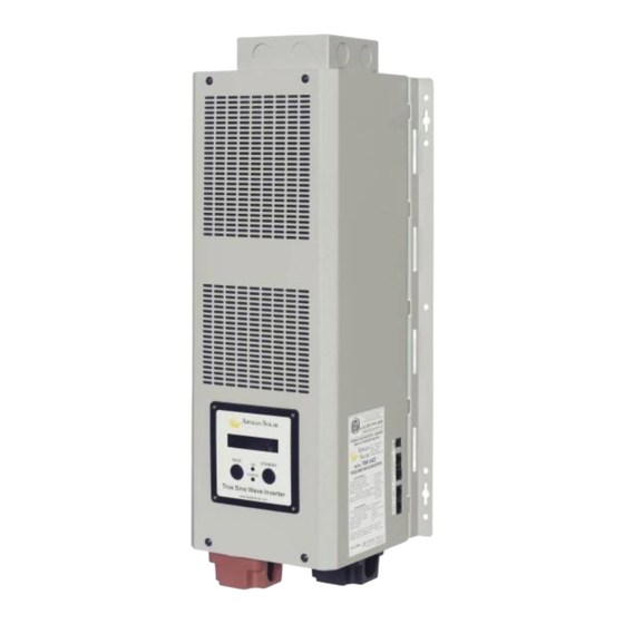
- Page 1 True Sine Wave Inverter / Charger TSW Series: 3224 / 4048 User’s Manual - 0 -...
-
Page 2: Table Of Contents
TABLE OF CONTENTS Purpose …………………………………………………………………………………… Scope ……………………………………………………………………………………… Audience ………………………………………………………………………………… Conventions Used ……………………………………………………………………… Important Safety Instructions ………………………………………………………… General Precautions ………………………………………………………………… Personal Precautions ………………………………………………………………… 1. Introduction ………………………………………………………………………… 1.1 Introduction to the Inverter … ………………………………………………...… 1.2 Indicators and Settings ………………………………………………….……… 2. The Battery Charger ……………………………………………………….………... - Page 3 4.2.2 Equipment or Chassis Grounds ……………………………………………………………… 4.2.3 Ground Electrodes / Ground Rods ………………………………………………………….. 4.2.4 Bonding the Grounding System to the Neutral and Negative Conductors ……. …………. 4.3 AC and DC Wiring ……………………………………………………………… 4.3.1 DC Wiring ……………………………………………………………………………………….. 4.3.1.1 DC Cable Connections ………………………………………………………………….. 4.3.1.2 Wiring the Battery Bank …………………………………………………………………...
-
Page 4: Purpose
Ces notes décrivent les choses il est importante savoir que, mais pas aussi sérieux qu'une attention ou un avertissement. Abbreviations and Acronyms Alternating Current Photovoltaic ASNET Apollo Solar Network Interface PVGFI PV Ground Fault Interrupter COMmunications Port Renewable Energy Direct Current... -
Page 5: Important Safety Instructions
IMPORTANT SAFETY INSTRUCTIONS INSTRUCTIONS DE SÉCURITÉS IMPORTANTES SAVE THESE INSTRUCTIONS CONSERVER CES INSTRUCTIONS General Precautions Before using the TSW inverter, please read all instructions and cautionary marks on (1) the inverter, (2) the batteries, and (3) all appropriate sections of this instruction manual. Do not expose INVERTER to rain, snow, or liquids of any type. -
Page 6: Personal Precautions
11. Personal Precautions 1. Someone should be within voice range when you work near batteries in case of an emergency. 2. Have plenty of fresh water and soap nearby in case battery acid contacts skin, clothing, or eyes. 3. Wear complete eye and clothing protection. Avoid touching eyes while working near batteries. Wash your hands when done. -
Page 7: Introduction
1/4~1/2 of the total cycle time. The high power charger (100A) can charge a 24V/1000 AH battery bank in 10 hours. For example, a single unit of Inverter TSW 3224 with a 1000 AH battery bank can supply a 3200W workload for over 6 hours after a charge of 10 hours. -
Page 8: Indicators And Settings
1.2 Indicators and Settings Figure 1.0: TSW Control Panel Display: This is a 16 character by 2 line LCD which provides operational information and setup prompts. Note: For detailed description of the LCD screens, refer to the Operation Section 5.0. On LED: Glows green to indicate that the inverter is powered on (i.e. -
Page 9: The Battery Charger
The Battery Charger utilizes a five stage charger algorithm (Bulk, Absorb, Float, Equalize and Standby). Figure 2.0 is a chart which illustrates the operation of this unit. APOLLO SOLAR T80 TurboCharger BATTERY CHARGING DETAILS ABSORB SET POINT... -
Page 10: Installation
3.0 Installation 3.1 Installation Steps 3.1.1 Selecting appropriate Location The Inverter is a sophisticated electronic device and should be treated accordingly. When selecting the operating environment for the inverter, do not think of it in the same terms as other equipment that works with it (e.g. -
Page 11: Inverter Mounting (Vertical)
3.1.2 Inverter Mounting (Vertical) The TSW Series inverter may be mounted vertically or horizontally. The vertical configuration is preferable when using the Apollo Solar Switch Gear. Apollo Switch Gear provides a convenient method for mounting other Balance of System (BOS) components such as circuit breakers, shunts, etc. -
Page 12: Wiring
4. Wiring APOLLO SOLAR AC OUT AC IN TSW 3224 or TSW 4048 TRUE SINE WAVE APOLLO SOLAR INVERTER/CHARGER TSW 3224 TRUE SINE WAVE INVERTER / CHARGER ACG-1 DC IN TurboCharger 125V DC BREAKERS AC BREAKERS BATTERY ARRAY APOLLO SOLAR T80... -
Page 13: Battery Information
4.1 Battery Information 4.1.1 Battery Size Batteries are the Inverter’s fuel tank. The larger the batteries the longer the INVERTER can operate before recharging is necessary. An undersized battery bank results in reduced battery life and disappointing system performance. Avoid discharging batteries to more than 50% of their capacity too often. Under extreme conditions, such as a severe storm or a long utility outage, cycling to a discharge level of 80% is acceptable. -
Page 14: Battery Hook-Up Configurations
To reduce corrosion on the battery terminals, coat them with a thin layer of petroleum jelly or anti-corrosion grease available from automotive parts stores or battery suppliers. Do not apply any material between the terminal and the cable lugs, the connection should be metal to metal. Apply the protective material after the bolts have been tightened 4.1.4 Battery Hook-up Configurations Battery banks of substantial size can be configured by connecting several smaller batteries. -
Page 15: Battery Installation
4.1.5 Battery Installation CAUTION Batteries can produce extremely high currents in short-circuit. Be very careful working around them. Read the important safety instructions at the beginning of this manual and the battery supplier's precautions before installing the Inverter and batteries ATTENTION Les batteries peuvent produire les courants extrêmement élevés dans le court-circuit. -
Page 16: Grounding
4.2 Grounding 4.2.1 System Grounding System grounding is often the most misunderstood wiring concept. The subject is more easily discussed if it is divided into three separate subjects. The grounding requirements vary widely by locale and application. Consult local codes and the NEC (ANSI/NFPA 70) for specific requirements. 4.2.2 Equipment or Chassis Grounds This is the simplest part of grounding. - Page 17 AC SYSTEM HOT IN HOT IN HOT OUT HOT OUT NEUTRAL NEUTRAL NEUTRAL BUS-BAR APOLLO SOLAR TSW INVERTER DC SYSTEM DC NEGATIVE BATTERY BUS-BAR SYSTEM CHASSIS GROUND CHASSIS GROUND GROUND BONDING BUS-BAR JUMPERS EQUIPMENT GROUND GROUNDING CONDUCTOR APOLLO SOLAR TSW...
-
Page 18: Ac And Dc Wiring
4.3 AC and DC Wiring APOLLO SOLAR TSW 3224 or TSW 4048 AC OUT AC IN TRUE SINE WAVE APOLLO SOLAR INVERTER/CHARGER TSW 3224 TRUE SINE WAVE INVERTER / CHARGER ACG-1 APOLLO SOLAR SWITCHGEAR MODULE ENCLOSURE DC IN TurboCharger 125V DC... - Page 19 Figure 4.3: A pair of TSW Inverters in complete system with Charge Controller from Photovoltaic input. Refer to section 4.3.4 for additional information on Stacking Inverters. Please note: DC grounds repositioned for clarity. APOLLO DC INPUT AC INPUT WIRING AC OUTPUT WIRING MODEL Amps 120 VAC...
-
Page 20: Dc Wiring
4.3.1 DC Wiring WARNING Even though DC Voltage is low voltage, significant hazards may exist, particularly from short circuits of the battery system. A 250A rated circuit breaker must be used on the DC input. AVERTISSEMENT Quoique la tension CC Soit basse tension, les risques significatifs peuvent exister, en particulier des courts-circuits de l'installation de batterie. -
Page 21: Dc Cable Connections
requires that the DC wiring and circuit protection be sized to carry not less than 125% of the inverter’s maximum current rating. Crimped and sealed copper ring terminal lugs with a 5/16” hole should be used to • connect the DC wires to the DC terminals. To ensure the maximum performance from the inverter, all connections from the battery •... -
Page 22: Battery Temperature Sensor Installation
3) la tension CC et la polarité Correcte a été vérifiée. Place the batteries as close as possible to the inverter, preferably in an insulated and ventilated enclosure. Allow adequate space above the batteries to access the terminals and vent caps (if flooded cells). - Page 23 DC Negative Cable – Route the appropriately sized cable from the battery negative terminal to the shunt, and from the other side of the shunt to the inverter’s negative DC terminal. IMPORTANT The side of the shunt that connects to the inverter should be considered the DC negative bus in order for the State of Charge (SOC) function to operate properly.
-
Page 24: Ac Wiring
4.3.2 AC Wiring WARNING Ensure that the DC input voltage to the inverter is not present prior to making AC connections to the inverter. AC INPUT / OUTPUT CONNECTIONS SUITABLE FOR USE WITH 90 C COPPER CONDUCTORS TORQUE CONNECTOR SCREWS TO 30 in-lbs / 3.4N-m AC INPUT FROM LINE AC OUTPUT TO LOAD OR GENERATOR... -
Page 25: Ac Wire Size And Overcurrent Protection
4.3.2.1 AC Wire Size and Overcurrent Protection AC input and output wiring must be sized per NEC (ANSI/NFPA 70) and local electrical safety code requirements to ensure the wires ability to safely handle the inverter’s maximum load current. Overcurrent protection devices are required to protect the inverter’s input and output wiring. Since overcurrent protection is not included in the inverter, it must be added at the time of installation. -
Page 26: Apollo Tsw Inverter Stacking
Follow these directions when connecting multiple inverters in parallel for increased current output. 4.4.1 Connection diagram : AC OUT AC IN AC OUT AC IN APOLLO SOLAR APOLLO SOLAR TSW 4048 TSW 4048 TRUE SINE WAVE TRUE SINE WAVE INVERTER / CHARGER... -
Page 27: Parameter Setting
Note: The following settings must be performed after the initial functional test (Section 5.1) 4.4.2 Parameter settings 1. Turn on Inverter 1 and press standby key to enter standby mode. 2. Press page key 5 seconds to enter communication ID setting. 3. -
Page 28: Operation
5. Operation 5.1 Functional Test and Initial Setup Step 1 Confirm all wiring is correct and terminals are tight. Step 2 Check that the voltage and polarity is correct. Turn on the DC circuit breaker. Step 3 The unit will auto start in inverter mode within 6 seconds after power (battery) is applied. Step 4 Apply AC input (utility or generator). -
Page 29: Charger Mode Main Status Screen
5.2.3 Inverter Mode Main Status Screen Upon entering Inverter Mode, the TSW displays Main Status Screen #1 which displays total power, line to line voltage and frequency. Pressing the “Page” key switches to screen #2: Main Status Screen #2; which reports total power, and AC Line 1 current and power. Pressing the “Page” key switches to screen #3: Main Status Screen #3 reports total power, and AC Line 2 current and power. -
Page 30: Error Messages
5.2.6 Error Messages All error messages are accompanied by an audible tone. Displayed when the Heatsink temperature is too high. Displayed when the Transformer temperature is too high. Displayed if a short circuit occurs on the output. Displays if battery voltage drops below the preset LBCO level. Displays if battery voltage rises above the preset HBCO level. -
Page 31: Technical Specification
ASNET (RS-485) and CANBUS O PT IO NAL ACCESSO RIES Charge Controllers Apollo Solar T 80 and T100 TurboCharger provide optimum charging from PV arrays. Ethernet / Internet Monitoring Optional Communication Gateway provides full data monitoring from any computer. Inverter Switchgear Module Optional Switchgear Module includes all the DC and AC circuit breakers required. -
Page 32: Troubleshooting
Technical Support. 8. Service and Support If you have any questions or problems with the TSW Series Inverter, call Apollo Solar and ask for a technical support representative. Please have the following information ready when you call Technical Support:... -
Page 33: Five Year Limited Warranty Information
Apollo Solar’s liability for any defective TSW Inverter/Charger or any part thereof shall be limited to the repair or replacement of the TSW, at Apollo Solar’s discretion. This warranty is limited to the TSW and in no way extends to cover the workmanship of any individual or firm installing the product. - Page 34 LIMITATIONS ON HOW LONG IMPLIED WARRANTY LASTS, SO THE ABOVE LIMITATION MAY NOT APPLY TO YOU. APOLLO SOLAR DOES NOT ACCEPT LIABILITY BEYOND THE REMEDIES SET FORTH IN THIS LIMITED WARRANTY STATEMENT OR LIABILITY FOR INCIDENTAL OR CONSEQUENTIAL DAMAGES, INCLUDING WITHOUT LIMITATION ANY LIABILITY FOR PRODUCTS NOT BEING AVAILABLE FOR USE.
Need help?
Do you have a question about the 3224 and is the answer not in the manual?
Questions and answers