
Related Manuals for Apollo Solar TurboCharger T80


Summary of Contents for Apollo Solar TurboCharger T80
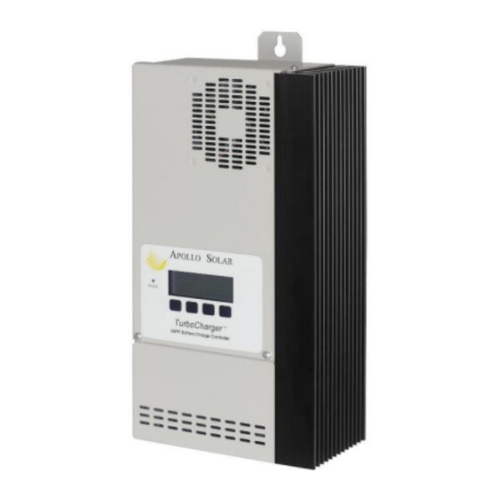
- Page 1 TurboCharger™ (For T80 & T80HV models) Installation and Operation Manual 23 Francis J. Clarke Circle, Bethel, CT 06801 USA (203) 790-6400 www.ApolloSolar.com...
-
Page 3: Table Of Contents
TurboCharger™ Installation and Operation Manual Page 1 TABLE OF CONTENTS Revision History ...................2 Important Safety Instructions................3 Overview ......................4 Theory of Operation …………………………………………………………… 5 Planning Your System..................6 Loads ....................6 Determining Battery Voltage..............6 Determining PV Array Voltage............7 Maximum Voc..................7 Conversion Efficiency ................8 Wire Sizing ..................8 Determining Maximum Current............9 Circuit Protection ................9... -
Page 4: Revision History
TurboCharger™ Installation and Operation Manual Page 2 Revision History Manual Revision Applies to Firmware Revision Date 3.20 12/12/06 3.20, 4.00, 4.03 4/24/07 3.20, 4.00, 4.03, 4.04, 5.00 6/29/07 1.91 5.00 7/16/07 5.04 7/23/07 6.03 10/19/07 2.11 6.06 1/31/08 6.10, 6.11 3/27/08 7.08, 7.09, 7.10 7/21/09... -
Page 5: Important Safety Instructions
⇒ Torque all connections to 50 lb-in (5.65 N-m) Apollo Solar recommends that all wiring be done by an electrician or certified technician in accordance to all local and national electrical codes applicable in your jurisdiction. Do not perform electrical work you do not feel qualified to do. -
Page 6: Overview
TurboCharger™ Installation and Operation Manual Page 4 OVERVIEW The Apollo TurboCharger™ is essentially a smart DC to DC converter which has been optimized to harvest maximum energy from the PV array in battery based solar electric systems by using a variety of maximum power point tracking (MPPT) strategies. -
Page 7: Theory Of Operation
TurboCharger™ Installation and Operation Manual Page 5 THEORY OF OPERATION Bulk: In the Bulk Mode the Controller is trying to get the battery voltage up to the Absorb Voltage Setting (B). It will use all the power it can get from the panels limited only by the Maximum Charge setting (A). When the Absorb Voltage is reached on the batteries, the charger switches into Absorb Mode. -
Page 8: Planning Your System
TurboCharger™ Installation and Operation Manual Page 6 PLANNING YOUR SYSTEM Loads Congratulations on choosing a solar electric system, when designed and installed properly it should give you decades of service life. The TurboCharger™ is a key component in your PV system. From a system planners perspective it is very flexible with the ability to accept a wide range of input voltages and produce a similarly wide range of output voltages. -
Page 9: Determining Pv Array Voltage
TurboCharger™ Installation and Operation Manual Page 7 Determining PV Array Voltage One of the great advantages of the DC to DC converter design of the TurboCharger™ is that PV array voltages are no longer dictated by the battery voltage. Sizing a PV array for the is much like sizing a grid- tie inverter, the same questions apply: What is the max and min Vmp and Voc of each string, how many strings will be needed. -
Page 10: Conversion Efficiency
TurboCharger™ Installation and Operation Manual Page 8 Conversion Efficiency The conversion efficiency of the TurboCharger™ in the proposed configuration must be considered. While it is possible to input 72 Vdc and output 12 Vdc, it is not the most efficient configuration for the controller. -
Page 11: Determining Maximum Current
In summary Apollo Solar recommends that the input breaker be 90 amps rated for 150 Vdc and the output breaker be 100 amps rated at a minimum of 80 Vdc. Apollo Solar and it’s distribution partners offer 90 and 100 amp breakers which are compatible with widely available PV system DC service entrance enclosures. -
Page 12: Lightning Protection
Combiner Box rated for 75º C for Battery, PV and Ground connections. Torque all terminals to 50 lb-in (5.64 N-m). Apollo Solar The Aux Relay screw terminals accept #14 to 22 AWG wire. Torque all signal terminals to 4.4 lb-in TurboCharger MODULAR CABLE WITH 3 (0.5 N-m). -
Page 13: Installation
TurboCharger™ Installation and Operation Manual Page 11 INSTALLATION Controller To minimize voltage drop and keep wiring and circuit protection costs down the TurboCharger™ should be located as close to the batteries as possible while still maintaining suitable distance to prevent any risk of fire from sparks and battery gasses. - Page 14 TurboCharger™ Installation and Operation Manual Page 12 Apollo Shunt The TurboCharger™ is designed to utilize a specially made shunt assembly. The Apollo Shunt is essential to operate at optimal levels and it serves as a hub for connecting critical measurement sensors. The main purpose of the shunt is to allow the TurboCharger™...
-
Page 15: Battery Temperature Sensor
TurboCharger™ Installation and Operation Manual Page 13 SHUNT WIRING DETAIL Voltage Sense Wire Installation— Push the white connector on the wire assembly FROM THE TurboCharger onto the white connector on the Apollo BATTERY TERMINALS MODULAR CABLE WITH 6 PIN RJ-11 AT BOTH ENDS PLUGS INTO THE OUTPUT TO DC Shunt circuit board after connecting the... -
Page 16: Initialization
TurboCharger™ Installation and Operation Manual Page 14 INITIALIZATION Each TurboCharger™ requires initialization when it is first installed and commissioned. The initialization process is the way that it “gets introduced” to its new environment. A series of screens take the installer through the installation process in a simple step-by-step manner. - Page 17 TurboCharger™ Installation and Operation Manual Page 15 3 Change Battery Voltage Screen S E T B A T T E R Y V O L T A G E S C R O L L W I T H - O R + K E Y S E L E C T E D V O L T S...
- Page 18 TurboCharger™ Installation and Operation Manual Page 16 The installer will prompted to enter a capacity. Once this is entered the NEXT key will display the first in a series of Battery Setup screens. These screens offer a manual override of the default generic settings for each battery type selected.
- Page 19 TurboCharger™ Installation and Operation Manual Page 17 5B Set Clock Screen S E T C L O C K M O D E = X X H r T I M E = H H : M M : S S A M D A T E = M M / D D / Y Y B A C K N E X T...
-
Page 20: Front Panel Led Status Indicator
TurboCharger™ Installation and Operation Manual Page 18 FRONT PANEL STATUS INDICATOR LED The Light Emitting Diode (LED) status indicator works in conjunction with the status screens. It is a three color LED (Green, Amber, Red) whose color indicates the following: Steady Amber: When the voltage from the PV array is first applied, the unit is preparing to •... -
Page 21: Operating The Turbocharger
TurboCharger™ Installation and Operation Manual Page 19 OPERATING THE TurboCharger STATUS SCREENS 1 Main Status Screen Once the initial setup is complete the TurboCharger™ operates automatically and displays the Main Status Screen. This screen provides vital PV system information at a glance and provides a portal to the data reporting and custom settings features. -
Page 22: Data Screens
TurboCharger™ Installation and Operation Manual Page 20 DATA SCREENS The TurboCharger™ Data screens are designed to offer the user a series of snap shots of energy harvested from the PV array. The series of screens offer scrollable; day-by-day, weekly or monthly views of energy harvest. -
Page 23: Setup
TurboCharger™ Installation and Operation Manual Page 21 3D Cumulative Data Screen #3.0 A V E R A G E L A S T D A Y S X X X X X K W H r X X X X A H r F L O A T M O D E = X X : X X... -
Page 24: Setup Selections Screen
TurboCharger™ Installation and Operation Manual Page 22 The table below shows the Default, Minimum, and Maximum settings for a variety of battery types and sizes. Note: all voltage values displayed are volts per 2 volt nominal cell. BATTERY CHARGE SETTINGS at 25 C Voltage Values Per 2 Volt Cell 12 Volt 24 Volt... -
Page 25: Main Eq Setup Screen
TurboCharger™ Installation and Operation Manual Page 23 1E Main EQ Setup Screen E Q U A L Z I Z A T I O N M A N U A L A U T O # # # D A Y S B A C K Y E S N E X T... - Page 26 TurboCharger™ Installation and Operation Manual Page 24 4E Manual Equalization Status Screen #2 T I M E L E F T = H H : M M H O T B A T = X X . X V T = X X º C C H A R G E = X X .
-
Page 27: Main Miscellaneous Setup Screen
TurboCharger™ Installation and Operation Manual Page 25 6E Auto Equalization Status Screen T I M E L E F T = H H : M M H O T B A T = X X . X V T = X X X C C H A R G E = X X . - Page 28 This screen is similar to the Welcome screen which is displayed when the unit first initializes. It is useful when contacting Apollo Solar Technical Support, as it displays the firmware revision, and unit serial number. The difference is that the second key, labeled FAN, toggles the fan on and off, this allows a test as it is thermostatically controlled and not always on (the * is present when the FAN is on), and the two right keys are activated to initiate the Bootloader function.
- Page 29 TurboCharger™ Installation and Operation Manual Page 27 There is a feature on this screen which allows the TurboCharger™ to be reset to the factory (out of box) settings. Note: This feature should only be performed by certified installers. To access this feature press and hold the second key from the left, and press the first (BACK) key.
-
Page 30: Aux Relay Setup Screen
TurboCharger™ Installation and Operation Manual Page 28 If Hold Input Voltage is selected, the following screen is displayed: M P P T S E T U P T Y P E = H O L D I N P U T H O L D I N P U T 1 4 0 . - Page 31 TurboCharger™ Installation and Operation Manual Page 29 3A AUX1/2 Battery Voltage Setup R E L A Y M O D E = B A T T O N < X X X . X V O F F > X X X . X V M I N .
- Page 32 TurboCharger™ Installation and Operation Manual Page 30 5A AUX1/2 Battery Current Setup R E L A Y M O D E = B A T T O N > X X X O F F < X X X M I N . O N = H H : M M R L Y : X B A C K...
- Page 33 TurboCharger™ Installation and Operation Manual Page 31 7A AUX1/2 Battery Temperature Setup R E L A Y M O D E = B A T T O N = X X X º C O F F = X X X º C M I N .
-
Page 34: Emonitor Setup Screen
TurboCharger™ Installation and Operation Manual Page 32 10A AUX1/2 Output Voltage Setup R E L A Y M O D E = O U T O N < X X X . X V O F F > X X X . X V M I N . -
Page 35: Wiring Diagram With Batteries
TurboCharger™ Installation and Operation Manual Page 33 Wiring Diagram with Batteries TURBOCHARGER BASIC SYSTEM Input from PV Array WIRING DIAGRAM or Combiner Box Apollo Solar TurboCharger MODULAR CABLE WITH 3 TWISTED PAIRS. FOR CURRENT SHUNT, BATTERY VOLTAGE +BAT+ -BAT- - PV -... -
Page 36: Networking (Stacking) Multiple Turbochargers
TurboCharger™ Installation and Operation Manual Page 34 Networking (Stacking) Multiple T80s How it works Input: Each unit operates the input side independently. That is each unit has its own PV Array and runs its own MPPT algorithm based on the conditions of that array. Output: All the Units in the Network work together on the output side. - Page 37 TurboCharger™ Installation and Operation Manual Page 35 2. Turn ON the battery breaker for the Master Unit. 3. The unit will come up with the Welcome Screen (it will not indicate a network option card unless one has been installed for a Remote Display). This screen remains for approximately 7 seconds. A P O L L O S O L A R T u r b o C h a r g e r...
- Page 38 TurboCharger™ Installation and Operation Manual Page 36 11. The following screen will appear. Press SAVE to save the setup. S E T U P D O N E R C L L = R E C A L L L A S T R C L L S A V E 12.
-
Page 39: Warranty Information
Apollo Solar’s liability for any defective TurboCharger™ or any part thereof shall be limited to the repair or replacement of the TurboCharger™, at Apollo Solar’s discretion. This warranty is limited to the TurboCharger™... -
Page 40: Appendix A - Wire Sizing Table For 1.5% Voltage Drop
Wire Sizing Table for 1.5% Voltage Drop The following chart provides the maximum distance from the PV array to the Apollo Solar T80HV Charge Controller. The chart assumes 2 conductor copper wire and allows for a 1.5% voltage drop. The figures are based on ASTM Specification B3-63. - Page 41 TurboCharger™ Installation and Operation Manual Page 39 "72 volt" PV array PV = 72 Volts WIRE GAUGE FROM PV ARRAY TO APOLLO SOLAR T80 Actually 96 Vmp PV Amps #1/0 #2/0 #4/0 108.9 173.1 275.3 437.6 695.8 878.0 1368.0 Use for 12, 54.4...
- Page 42 WIRE DISTANCE CHART -- IN METERS MAXIMUM VOLTAGE DROP = 1.50% LENGTH OF WIRE PAIR IN METERS FROM PV ARRAY TO THE T80HV CHARGE CONTROLLER "12 volt" PV array PV = 12 Volts WIRE GAUGE FROM PV ARRAY TO APOLLO SOLAR T80 Actually 16 Vmp PV Amps #1/0 #2/0 #4/0 14.0...
- Page 43 TurboCharger™ Installation and Operation Manual Page 41 "72 volt" PV array PV = 72 Volts WIRE GAUGE FROM PV ARRAY TO APOLLO SOLAR T80 Actually 96 Vmp PV Amps #1/0 #2/0 #4/0 33.2 52.8 83.9 133.4 212.2 267.7 425.6 Use for 12, 16.6...
- Page 44 TurboCharger™ Installation and Operation Manual Page 42 The following chart provides the maximum distance from the Apollo Solar T80HV Charge Controller to the batteries. WIRE DISTANCE CHART - IN FEET MAXIMUM VOL TAG E DRO P = 1.43% LENGT H OF WIRE PAIR IN FEET FROM T80HV CHARGE CONTROL LER TO BAT TERY...
- Page 45 TurboCharger™ Installation and Operation Manual Page 43 WIRE DISTANCE CHART - IN MET ERS MAXIMUM VOL TAG E DRO P = 1.43% LENGT H OF WIRE PAIR IN METERS F ROM T80HV CHARGE CO NT RO LLER T O BATTERY 12 VOL T BATT WIRE GAUGE FROM APOL LO SOLAR T80 TO BATT ERY IN METERS...
-
Page 46: Appendix B - Bootloader Function
This is the screen is similar to the Welcome screen which is displayed when the unit first initializes. It is useful when contacting Apollo Solar Technical Support, as it displays the firmware revision, and unit serial number. The difference is that the two right keys are activated to initiate the Bootloader function. Press the BACK key to return to the main screen.
Need help?
Do you have a question about the TurboCharger T80 and is the answer not in the manual?
Questions and answers