Heat & Glo 8000TV-OAK Owner's Manual
Installation and operation
Hide thumbs
Also See for 8000TV-OAK:
- Brochure (8 pages) ,
- Owner's manual (42 pages) ,
- Owner's manual (46 pages)
Table of Contents
Advertisement
Quick Links
Models:
8000TV-OAK
8000TV-OAK-IPI
8000TVLP-OAKIPI
• Important operating
a n d m a i n t e n a n c e
instructions included.
WARNING: If the information in these
instructions is not followed exactly, a fi re
or explosion may result causing property
damage, personal injury, or death.
• DO NOT store or use gasoline or other fl am-
mable vapors and liquids in the vicinity of this
or any other appliance.
• What to do if you smell gas
- DO NOT try to light any appliance.
- DO NOT touch any electrical switch. DO
NOT use any phone in your building.
- Immediately call your gas supplier from a
neighbor's phone. Follow the gas suppli-
er's instructions.
- If you cannot reach your gas supplier, call
the fi re department.
• Installation and service must be performed
by a qualifi ed installer, service agency, or the
gas supplier.
Heat & Glo • 8000TV-OAK, 8000TV-OAK-IPI, 8000TVLP-OAKIPI • 2058-900 Rev. N • 11/08
NOTICE
DO NOT DISCARD THIS MANUAL
• Read, understand and follow
these instructions for safe
installation and operation.
Owner's Manual
• Leave this manual with
party responsible for use
and operation.
WARNING
HOT SURFACES!
Glass and other surfaces are hot during
operation AND cool down.
Hot glass will cause burns.
• DO NOT touch glass until it is cooled
• NEVER allow children to touch glass
• Keep children away
• CAREFULLY SUPERVISE children in same room as
fi replace.
• Alert children and adults to hazards of high temperatures.
High temperatures may ignite clothing or other fl ammable
materials.
• Keep clothing, furniture, draperies and other fl ammable
materials away.
This appliance has been supplied with an integral barrier
to prevent direct contact with the fi xed glass panel. DO
NOT operate the appliance with the barrier removed.
Contact your dealer or Hearth & Home Technologies if the
barrier is not present or help is needed to properly install one.
In the Commonwealth of Massachusetts installation must be
performed by a licensed plumber or gas fi tter.
A CO detector shall be installed in the room where the appliance
in installed.
Installation and service of this appliance should be
performed by qualifi ed personnel. Hearth & Home
Technologies suggests NFI certifi ed or factory trained
professionals, or technicians supervised by an NFI
certifi ed professional.
Installation and Operation
1
Advertisement
Table of Contents

Related Manuals for Heat & Glo 8000TV-OAK


Summary of Contents for Heat & Glo 8000TV-OAK
- Page 1 • Installation and service must be performed by a qualifi ed installer, service agency, or the gas supplier. Heat & Glo • 8000TV-OAK, 8000TV-OAK-IPI, 8000TVLP-OAKIPI • 2058-900 Rev. N • 11/08 NOTICE DO NOT DISCARD THIS MANUAL • Read, understand and follow these instructions for safe installation and operation.
-
Page 2: Congratulations
MAX. INPU T BTUH: MIN. INPU T BTUH: ORIFICE SIZE: Heat & Glo • 8000TV-OAK, 8000TV-OAK-IPI, 8000TVLP-OAKIPI • 2058-900 Rev. N • 11/08 This owner’s manual should be retained for future reference. We suggest that you keep it with your other important documents and product manuals. -
Page 3: Table Of Contents
E. Negative Pressure ......18 Heat & Glo • 8000TV-OAK, 8000TV-OAK-IPI, 8000TVLP-OAKIPI • 2058-900 Rev. N • 11/08... - Page 4 C. Contact Information ......46 = Contains updated information. Heat & Glo • 8000TV-OAK, 8000TV-OAK-IPI, 8000TVLP-OAKIPI • 2058-900 Rev. N • 11/08...
-
Page 5: Limited Lifetime Warranty
• Adjustments, regular maintenance, cleaning and temporary repairs, or the failure to duplicate the problem in the home is not covered under this warranty. Page 1 of 2 Heat & Glo • 8000TV-OAK, 8000TV-OAK-IPI, 8000TVLP-OAKIPI • 2058-900 Rev. N • 11/08 Wood Pellet... - Page 6 If warranty service is needed, you should contact your installing dealer. If the installing dealer is unable to provide necessary parts or components, contact the nearest authorized HHT dealer or supplier. Page 2 of 2 Heat & Glo • 8000TV-OAK, 8000TV-OAK-IPI, 8000TVLP-OAKIPI • 2058-900 Rev. N • 11/08 4021-645A 09-01-08...
-
Page 7: Listing And Code Approvals
Glass meeting this requirement is available from the factory. Please contact your dealer or distributor to order. Heat & Glo • 8000TV-OAK, 8000TV-OAK-IPI, 8000TVLP-OAKIPI • 2058-900 Rev. N • 11/08 C. BTU Specifi cations Maximum... -
Page 8: User Guide
• Install a switch lock or a wall/remote control with child protection lockout feature. Figure 2.1 General Operating Parts Heat & Glo • 8000TV-OAK, 8000TV-OAK-IPI, 8000TVLP-OAKIPI • 2058-900 Rev. N • 11/08 User Guide • Keep remote controls out of reach of children. -
Page 9: Fan Kit (Optional)
Switches Follow the instructions supplied with the control installed to operate your fi replace: Heat & Glo • 8000TV-OAK, 8000TV-OAK-IPI, 8000TVLP-OAKIPI • 2058-900 Rev. N • 11/08 For safety: • Install a switch lock or a wall/remote control with child protection lockout feature. -
Page 10: For Your Safety Read Before Lighting
For additional information on operating your Hearth & Home Technologies fi replace, please refer to www.fi replaces.com. Final inspection by Heat & Glo • 8000TV-OAK, 8000TV-OAK-IPI, 8000TVLP-OAKIPI • 2058-900 Rev. N • 11/08 • Immediately call your gas supplier from a neighbor’s phone. Follow the gas supplier’s instructions. -
Page 11: Lighting Instructions (Standing Pilot)
Hearth & Home Technologies fi replace, please refer to www.fi replaces.com. Final inspection by Heat & Glo • 8000TV-OAK, 8000TV-OAK-IPI, 8000TVLP-OAKIPI • 2058-900 Rev. N • 11/08 • If you cannot reach your gas sup- plier, call the fi re department. -
Page 12: After Fireplace Is Lit
Is it normal to see the pilot fl ame burn continually? Heat & Glo • 8000TV-OAK, 8000TV-OAK-IPI, 8000TVLP-OAKIPI • 2058-900 Rev. N • 11/08 This is a result of gas combustion and temperature variations. As the appliance warms, this condensation will disappear. -
Page 13: Maintenance And Service
Hold glass in place with one hand and secure glass latches with the other hand. • Reinstall door or decorative front. Heat & Glo • 8000TV-OAK, 8000TV-OAK-IPI, 8000TVLP-OAKIPI • 2058-900 Rev. N • 11/08 Doors, Surrounds, Fronts Frequency: Annually By: Homeowner Tools needed: Protective gloves, stable work surface •... -
Page 14: Maintenance Tasks-Qualifi Ed Service Technician
• Inspect for paint condition, warped surfaces, corrosion or perforation. Sand and repaint as necessary. • Replace fi replace if fi rebox has been perforated. Heat & Glo • 8000TV-OAK, 8000TV-OAK-IPI, 8000TVLP-OAKIPI • 2058-900 Rev. N • 11/08 Control Compartment and Firebox Top Frequency: Annually By: Qualifi... - Page 15 (Either cobrahead or SIT) Figure 3.1 IPI Pilot Flame Patterns Figure 3.2 Standing Pilot Flame Patterns Heat & Glo • 8000TV-OAK, 8000TV-OAK-IPI, 8000TVLP-OAKIPI • 2058-900 Rev. N • 11/08...
-
Page 16: Installer Guide
(SECTION 8.B) FRAMING/HEADER (SECTION 5) GAS LINE SECTION Figure 4.1 Typical System Heat & Glo • 8000TV-OAK, 8000TV-OAK-IPI, 8000TVLP-OAKIPI • 2058-900 Rev. N • 11/08 Installer Guide VERTICAL TERMINATION CAP (SECTION 4.D) STORM COLLAR (SECTION 4.D) VENT PIPE PENETRATES ROOF PREFERABLY WITHOUT AFFECTING ROOF RAFTERS (SECTIONS 8.B and 8.C) -
Page 17: Design And Installation Considerations
• Storm Collar • Carefully remove the appliance and components from the packaging. Heat & Glo • 8000TV-OAK, 8000TV-OAK-IPI, 8000TVLP-OAKIPI • 2058-900 Rev. N • 11/08 • The vent system components and decorative doors and fronts may be shipped in separate packages. -
Page 18: Negative Pressure
Recommended Windward Figure 4.2 Heat & Glo • 8000TV-OAK, 8000TV-OAK-IPI, 8000TVLP-OAKIPI • 2058-900 Rev. N • 11/08 • Ensure adequate outdoor air is supplied for combustion appliances and exhaust equipment. • Ensure furnace and air conditioning return vents are not located in the immediate vicinity of the fi... -
Page 19: Framing And Clearances
Inches Millimeters Figure 5.1 Appliance Locations Heat & Glo • 8000TV-OAK, 8000TV-OAK-IPI, 8000TVLP-OAKIPI • 2058-900 Rev. N • 11/08 NOTICE: Illustrations refl ect typical installations and are FOR DESIGN PURPOSES ONLY. Illustrations/diagrams are not drawn to scale. Actual installation may vary due to individual design preference. -
Page 20: Constructing The Appliance Chase
* Adjust framing dimensions for interior sheathing (such as sheetrock) Figure 5.2 Clearances to Combustibles Heat & Glo • 8000TV-OAK, 8000TV-OAK-IPI, 8000TVLP-OAKIPI • 2058-900 Rev. N • 11/08 To further prevent drafts, the wall shield and ceiling fi re- stops should be caulked with high temperature caulk to seal gaps. -
Page 21: Mantel And Wall Projections
TOP FRONT EDGE OF FIREPLACE TOP OF HOOD Figure 5.3 Minimum Vertical and Maximum Horizontal Dimensions of Combustibles Heat & Glo • 8000TV-OAK, 8000TV-OAK-IPI, 8000TVLP-OAKIPI • 2058-900 Rev. N • 11/08 Combustible Mantel Legs or Wall Projections CEILING Note: Clearance from opening to perpendicular wall. -
Page 22: Termination Locations
Over 20/12 to 21/12 ...8.0 * 3 foot minimum in snow regions Figure 6.1 Minimum Height From Roof To Lowest Discharge Opening Heat & Glo • 8000TV-OAK, 8000TV-OAK-IPI, 8000TVLP-OAKIPI • 2058-900 Rev. N • 11/08 VERTICAL WALL Figure 6.2 Staggered Termination Caps... -
Page 23: Vent Information And Diagrams
• Install fi restops as specifi ed. Failure to keep insulation or other material away from vent pipe may cause fi re. Heat & Glo • 8000TV-OAK, 8000TV-OAK-IPI, 8000TVLP-OAKIPI • 2058-900 Rev. N • 11/08 Note: Other vent components are noted in Figure 4.2... -
Page 24: Vent Clearances And Framing
Failure to keep insulation or other material away from vent pipe may cause over heating and fi re. Heat & Glo • 8000TV-OAK, 8000TV-OAK-IPI, 8000TVLP-OAKIPI • 2058-900 Rev. N • 11/08 B. Wall and Ceiling Penetration Framing For a wall or ceiling penetration consult B-vent pipe manufacturer’s instructions to provide adequate clear-... -
Page 25: Appliance Preparation
• Check handle operation. Pull handle out to open, and in to close. Figure 9.2 Outside Air Kit Installation Heat & Glo • 8000TV-OAK, 8000TV-OAK-IPI, 8000TVLP-OAKIPI • 2058-900 Rev. N • 11/08 B. Gas and Electrical Connections If applicable, ensure that gas and electrical connections are installed at this time. -
Page 26: Completing Grate Set-Up
Figure 9.5 Re-install grate in unit 4. Reinstall grate into unit (see Figure 9.5). Heat & Glo • 8000TV-OAK, 8000TV-OAK-IPI, 8000TVLP-OAKIPI • 2058-900 Rev. N • 11/08 E. Checking Pilot Plate Note: Ensure pilot plate is in place. This will ensure pilot stability (see Figure 9.6) -
Page 27: Installing Vent Pipe
SCREWS FLUE OUTLET COLLAR Figure 10.1 Heat & Glo • 8000TV-OAK, 8000TV-OAK-IPI, 8000TVLP-OAKIPI • 2058-900 Rev. N • 11/08 C. Securing Vent Sections Secure vent sections with vent supports following B-vent manufacturer’s instructions. WARNING! Risk of Fire or Explosion! Use vent run sup- ports per vent manufacturer’s installation instructions. -
Page 28: Gas Information
• If substituting for these components, please consult local codes for compliance. Heat & Glo • 8000TV-OAK, 8000TV-OAK-IPI, 8000TVLP-OAKIPI • 2058-900 Rev. N • 11/08 C. Gas Connection • Refer to Reference Section 16 for location of gas line access in appliance. -
Page 29: Electrical Information
RED OR BLACK BUTTON Figure 12.1 Ignitor Button Heat & Glo • 8000TV-OAK, 8000TV-OAK-IPI, 8000TVLP-OAKIPI • 2058-900 Rev. N • 11/08 B. Standing Pilot Ignition System Wiring • The standing pilot ignition system wiring does not require a 110 VAC supply to operate. See Figure 12.3. -
Page 30: Electrical Service And Repair
WHITE PILOT PIEZO THERMOCOUPLE VALVE THERMOSTAT WIRE ASSEMBLY Figure 12.3 Standing Pilot Ignition Wiring Diagram Heat & Glo • 8000TV-OAK, 8000TV-OAK-IPI, 8000TVLP-OAKIPI • 2058-900 Rev. N • 11/08 INTERMITTENT PILOT IGNITOR WHITE GROUND TO FIREPLACE CHASSIS TRANSFORMER PLUG-IN BATTERY PACK VALVE NOTE: 1. -
Page 31: Junction Box Installation
(1/4 in. male) as shown. Heat & Glo • 8000TV-OAK, 8000TV-OAK-IPI, 8000TVLP-OAKIPI • 2058-900 Rev. N • 11/08 GRN wire inside box NOTICE: DO NOT wire 110 VAC to wall switch. -
Page 32: Finishing
MIN. Figure 13.2 Combustible Mantel Leg or Wall Projections (Acceptable on both sides of opening) Heat & Glo • 8000TV-OAK, 8000TV-OAK-IPI, 8000TVLP-OAKIPI • 2058-900 Rev. N • 11/08 B. Facing Material • Metal front faces may be covered with non-combustible materials only. -
Page 33: Appliance Setup
E. Install the Refractory Install optional refractory following instructions in refractory kit. Heat & Glo • 8000TV-OAK, 8000TV-OAK-IPI, 8000TVLP-OAKIPI • 2058-900 Rev. N • 11/08 F. Ember Placement WARNING! Risk of Explosion! Follow ember placement instructions in manual. DO NOT place embers directly over burner ports. -
Page 34: Install The Log Assembly
B is located at the back/right corner of burner. NOTE: There should be a 1/2 inch gap between the bottom of log 3 and the top edge of the burner. The underside of log #3 must not cover ANY burner ports. Heat & Glo • 8000TV-OAK, 8000TV-OAK-IPI, 8000TVLP-OAKIPI • 2058-900 Rev. N • 11/08 Log Assembly: LOGS-8OAK... - Page 35 This is key in avoiding fl ame impingement. NOTE: Finished top view. Heat & Glo • 8000TV-OAK, 8000TV-OAK-IPI, 8000TVLP-OAKIPI • 2058-900 Rev. N • 11/08 STEP 6: interlock with front left corner of grate. Rest right end of log so that it engages tab on log 3.
-
Page 36: Fixed Glass Assembly
AND TOP) GLASS ASSEMBLY Figure 14.3 Fixed Glass Assembly Heat & Glo • 8000TV-OAK, 8000TV-OAK-IPI, 8000TVLP-OAKIPI • 2058-900 Rev. N • 11/08 I. Install the Mesh The screen mesh is a protective barrier and must be at- tached. J. Install Trim and/or Surround •... -
Page 37: Troubleshooting
ON position. B. Thermopile may not be gen- erating suffi cient millivoltage. Heat & Glo • 8000TV-OAK, 8000TV-OAK-IPI, 8000TVLP-OAKIPI • 2058-900 Rev. N • 11/08 Corrective Action Check the remote shut-off valves from the appliance. Usually, there is a valve near the gas main. There can be more than one valve be- tween the appliance and the main. - Page 38 7. Flame burns blue A. Insuffi cient oxygen being supplied. and lifts off burner. Heat & Glo • 8000TV-OAK, 8000TV-OAK-IPI, 8000TVLP-OAKIPI • 2058-900 Rev. N • 11/08 Possible Cause Negative pressure, wind or fl ue blockage may be causing spillage. Perform negative pressure diagnos- tics and inspect venting.
-
Page 39: Intellifi Re Ignition System
C. Module is not grounded. D. Module voltage output / Valve/Pilot solenoid ohms readings. Heat & Glo • 8000TV-OAK, 8000TV-OAK-IPI, 8000TVLP-OAKIPI • 2058-900 Rev. N • 11/08 Corrective Action Verify “S” wire (white) for sensor and “I” wire (orange) for ignitor are connected to correct terminals on module and pilot assembly. - Page 40 D. Damaged pilot assembly or contami- nated fl ame sensing rod. E. Module. Heat & Glo • 8000TV-OAK, 8000TV-OAK-IPI, 8000TVLP-OAKIPI • 2058-900 Rev. N • 11/08 Possible Cause Verify all connections to wiring diagram in manual. Verify connections underneath pilot assembly are tight. Verify con-...
-
Page 41: Reference Materials
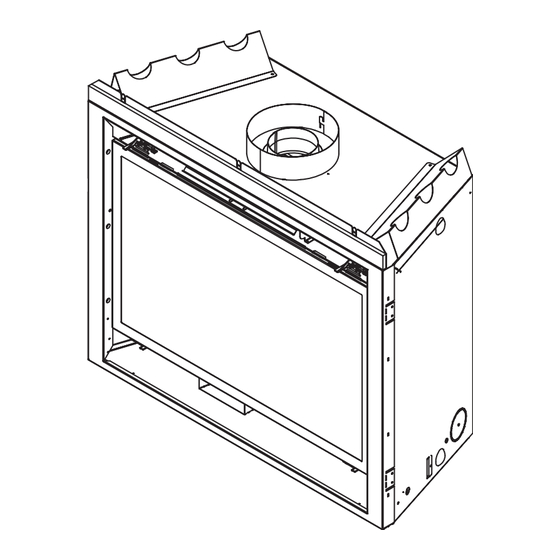
Dimensions are actual appliance dimensions. Use for reference only. For framing dimensions and clearances refer to Section 5. GAS LINE ACCESS Location Figure 16.1 Appliance Dimensions Heat & Glo • 8000TV-OAK, 8000TV-OAK-IPI, 8000TVLP-OAKIPI • 2058-900 Rev. N • 11/08 Inches Millimeters Location 35-1/2... -
Page 42: Service Parts
8000TV-OAK, 8000TV-OAK-IPI B. Service Parts Beginning Manufacturing Date: Feb. 2005 Service Parts Diagram Ending Manufacturing Date: ______ Log Set Assembly Part number list on following page. Heat & Glo • 8000TV-OAK, 8000TV-OAK-IPI, 8000TVLP-OAKIPI • 2058-900 Rev. N • 11/08... -
Page 43: Service Parts List
Regulator LP Pilot Orifi ce NG Pilot Orifi ce LP Addional service part numbers appear on following page Heat & Glo • 8000TV-OAK, 8000TV-OAK-IPI, 8000TVLP-OAKIPI • 2058-900 Rev. N • 11/08 COMMENTS Standing Pilot Ignition Only Pre 0021116948 Post 0021116948... - Page 44 Valve NG Valve LP Module Wire Assembly Battery Pack 3 Volt Transformer 80”& 72” Wire Assembly Heat & Glo • 8000TV-OAK, 8000TV-OAK-IPI, 8000TVLP-OAKIPI • 2058-900 Rev. N • 11/08 COMMENTS Pre 002927628 Post 002927628 Pre 002927628 Post 002927628 Pre 002927628...
- Page 45 Valve Bracket Valve NG Valve LP Piezo Ignitor ON/OFF Rocker Switch Wire Assembly 80” Wire Assembly Heat & Glo • 8000TV-OAK, 8000TV-OAK-IPI, 8000TVLP-OAKIPI • 2058-900 Rev. N • 11/08 Pre 0021116948 Post 0021116948 Pre 0021116948 Post 0021116948 Pre 0021116948 Post 0021116948...
-
Page 46: Contact Information
D462436; (Canada) 1297749, 2195264, 2225408, 2313972; (Australia) 780250, 780403, 1418504 or other U.S. and foreign patents pending. Heat & Glo • 8000TV-OAK, 8000TV-OAK-IPI, 8000TVLP-OAKIPI • 2058-900 Rev. N • 11/08 Heat & Glo, a brand of Hearth & Home Technologies Inc.
Need help?
Do you have a question about the 8000TV-OAK and is the answer not in the manual?
Questions and answers