
Related Manuals for Hayter RZT420H


Summary of Contents for Hayter RZT420H
- Page 1 RZT420H Ride-On with Recycling/Side Discharge Deck Code 136E Serial No. 280000001 Manual Part No. 111-2089 Rev B...
-
Page 2: Table Of Contents
Introduction Read this information carefully to learn how to operate and maintain your product properly and to avoid injury and product damage. You are responsible for operating the product properly and safely. Whenever you need service, genuine Hayter parts, or additional information, contact an Authorized Service Dealer or Hayter Customer Service and have the model and serial numbers of your product ready. -
Page 3: Safety
Servicing the Air Cleaner ... 28 Servicing the Engine Oil ... 29 Servicing the Spark Plug ... 31 Cleaning the Blower Housing... 31 Fuel System Maintenance ... 32 Replacing the Fuel Filter ... 32 Electrical System Maintenance... 33 Charging the Battery... 33 Servicing the Fuses ... - Page 4 ◊ lack of awareness of the effect of ground conditions, especially slopes; ◊ incorrect hitching and load distribution. Preparation • While mowing, always wear substantial footwear and long trousers. Do not operate the equipment when barefoot or wearing open sandals. •...
-
Page 5: Z Turn Riding Mower Safety
Maintenance and Storage • Keep all nuts, bolts and screws tight to be sure the equipment is in safe working condition. • Never store the equipment with fuel in the tank inside a building where fumes can reach an open flame or spark. -
Page 6: Slope Chart
Slope Chart... -
Page 7: Safety And Instructional Decals
Safety decals and instructions are easily visible to the operator and are located near any area of potential danger. Replace any decal that is damaged or lost. 114-1606 1. Entanglement hazard, belt—keep all guards in place. 93-7009 1. Warning—don’t operate the mower with the deflector up or removed;... - Page 8 110-6824 1. Height-of-cut 115-2500 1. Choke 5. Power take-off (PTO), Blade control switch on some models 2. Fast 6. Blade control switch—Off 3. Continuous variable 7. Blade control switch—On setting 4. Slow 112-9750 1. Parking position 4. Neutral 2. Fast 5.
- Page 9 Battery Symbols Some or all of these symbols are on your battery 1. Explosion hazard 6. Keep bystanders a safe distance from the battery. 2. No fire, open flame, or 7. Wear eye protection; smoking. explosive gases can cause blindness and other injuries 3.
-
Page 10: Figure
Setup Loose Parts Use the chart below to verify that all parts have been shipped. Procedure No parts required Clevis pin Hair Pin No parts required Ignition Key Operator’s Manual Engine Operator’s Manual Note: Determine the left and right sides of the machine from the normal operating position. Setting Up the Motion Control Levers No Parts Required Procedure... - Page 11 3. Open the motion control levers and raise the seat (Figure 4). Move the control levers back to the center position (neutral). 4. Verify the motion control levers are properly aligned (Figure 5). Adjust as necessary. Tighten all fasteners. Figure 4 Figure 5...
-
Page 12: Installing The Seat Cable
Installing the Seat Cable Parts needed for this procedure: Clevis pin Hair Pin Procedure 1. Open the motion control levers and raise the seat. 2. Locate the seat cable secured to the frame. Locate the clevis and hair pins installed on the loose end of the seat cable. -
Page 13: Completing The Setup
Completing the Setup Parts needed for this procedure: Ignition Key Operator’s Manual Engine Operator’s Manual Procedure Checking the Tyre Pressure Check the front and rear tyres for proper inflation. Refer to Checking the Tyre Pressure in the Operator’s Manual for the recommended inflation pressure. Checking the Side Discharge Chute Remove the packing restraint holding the side discharge chute up and lower the chute into place. -
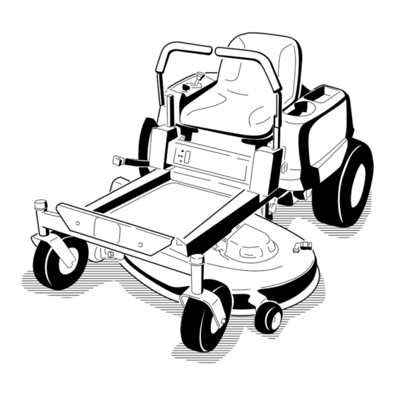
Page 14: Product Overview
Product Overview 1. Footrest 4. Control panel 2. Height of cut lever 5. Motion control levers 3. Fuel gauge 6. Operator seat 1. Motion control levers 2. Height of cut lever Figure 8 7. Rear drive wheel 8. Washout fitting 9. -
Page 15: Controls
Become familiar with all of the controls in Figure 8, Figure 9, and Figure 10 before you start the engine and operate the machine. Figure 10 Control Panel 1. Ignition switch 3. Blade control switch 2. Throttle/Choke Ignition Switch The ignition switch has three positions, Off, Run and Start. -
Page 16: Operation
Operation Note: Determine the left and right sides of the machine from the normal operating position. Think Safety First Please carefully read all of the safety instructions and decals in the safety section. Knowing this information could help you, your family, pets or bystanders avoid injury. -
Page 17: Filling The Fuel Tank
In certain conditions during fueling, static electricity can be released causing a spark which can ignite the petrol vapors. A fire or explosion from petrol can burn you and others and can damage property. • Always place petrol containers on the ground away from your vehicle before filling. -
Page 18: Checking The Engine Oil Level
Before you start the engine and use the machine, check the oil level in the engine crankcase; refer to Checking the Oil Level in the Engine Maintenance section. Starting the Engine 1. Sit down on the seat and move the motion controls outward to the park position. -
Page 19: Operating The Blades
5. After the engine starts, move the throttle lever to Fast (Figure 16). If the engine stalls or hesitates, move the throttle lever back to Choke for a few seconds. Repeat this as required. Operating the Blades The blade control switch, represented by a power take-off (PTO) symbol, engages and disengages power to the cutting blades. -
Page 20: Testing The Safety Interlock System
Testing the Safety Interlock System Test the safety interlock system before you use the machine each time. If the safety system does not operate as described below, have an Authorized Service Dealer repair the safety system immediately. 1. While sitting on the seat, with the control levers in park position, and move the blade control switch to On. -
Page 21: Adjusting The Height Of Cut
blade control switch, ensure the throttle is in the fast position, and turn the ignition key to off. Remember to remove the key from the ignition switch. Children or bystanders may be injured if they move or attempt to operate the machine while it is unattended. -
Page 22: Pushing The Machine By Hand
Adjusting the Tilt The motion control levers can be tilted fore or aft for maximum operator comfort. 1. Loosen the upper bolt holding the control lever to the control arm shaft. 2. Loosen the lower bolt just enough to pivot the control lever fore or aft (Figure 23). -
Page 23: Removing And Installing The Discharge Cover
Without the grass deflector, discharge cover, or complete grass catcher assembly mounted in place, you and others are exposed to blade contact and thrown debris. Contact with rotating cutter deck blade(s) and thrown debris will cause injury or death. • Never remove the grass deflector from the cutter deck because the grass deflector routes material down toward the turf. -
Page 24: Operating Tips
Operating Tips Fast Throttle Setting For best mowing and maximum air circulation, operate the engine at the Fast position. Air is required to thoroughly cut grass clippings, so do not set the height-of-cut so low as to totally surround the cutter deck by uncut grass. -
Page 25: Maintenance
Maintenance Note: Determine the left and right sides of the machine from the normal operating position. Recommended Maintenance Schedule(s) Maintenance Service Maintenance Procedure Interval • Check the safety interlock system. • Check the air cleaner for dirty, loose or damaged parts. •... -
Page 26: Premaintenance Procedures
Premaintenance Procedures Raising the Seat Make sure the motion control levers are locked in the park position. Lift the seat forward. The following components can be accessed by raising the seat: • Serial plate • Service decal • Seat adjustment knob •... -
Page 27: Lubrication
Figure 29 1. Left cover 3. Battery 2. Torx head fasteners (T25) 4. Lift the plastic cover away from the machine. Retain all fasteners. Replace the cover and secure it to the frame using the fasteners removed previously. Lubrication Greasing the Bearings Service Interval: Every 25 hours—Grease all lubrication points. -
Page 28: Engine Maintenance
4. Connect a grease gun to each fitting (Figure 30 and Figure 31). Pump grease into the fittings until grease begins to ooze out of the bearings. 5. Wipe up any excess grease. Engine Maintenance Servicing the Air Cleaner Service Interval: Before each use or daily—Check the air cleaner for dirty, loose or damaged parts. -
Page 29: Servicing The Engine Oil
Replace a dirty, bent, or damaged element. Handle new elements carefully; do not use if the rubber seal is damaged. 4. Clean all air cleaner components of any accumulated dirt or foreign material. Prevent any dirt from entering the carburettor. 5. - Page 30 2. Park the machine so that the drain side is slightly lower than the opposite side to assure the oil drains completely. 3. Disengage the blade control switch and move the motion controls outward to the park position. 4. Stop the engine, remove the key, and wait for all moving parts to stop before leaving the operating position.
-
Page 31: Servicing The Spark Plug
Figure 37 3. Adapter 1. Oil filter 2. Gasket 15. Slowly pour approximately 80% of the specified oil into the filler tube (Figure 34). 16. Install the oil fill cap/dipstick and push firmly into place (Figure 34). 17. Check the oil level (Figure 34); refer to Checking the Oil Level. -
Page 32: Fuel System Maintenance
Annually or every 100 hours of operation (more often under extremely dusty, dirty conditions), remove the blower housing and any other cooling shrouds. Clean the cooling fins and external surfaces as necessary. Make sure the cooling shrouds are reinstalled. Torque the blower housing screws to 5.5 ft-lb (7.5 N-m). -
Page 33: Removing The Battery
Figure 40 1. Fuel line from tank 4. Fuel line to engine 2. Hose clamp 5. Flow direction arrow 3. Filter 6. Fuel tank 4. Squeeze the ends of the hose clamps together and slide them away from the filter (Figure 40). 5. -
Page 34: Installing The Battery
5. Slide the rubber cover up the positive (red) cable. Disconnect the positive (red) cable from the battery post (Figure 41). Retain all fasteners. 6. Remove the battery hold-down (Figure 41) and lift the battery from the battery tray. Figure 41 1. -
Page 35: Drive System Maintenance
Drive System Maintenance Checking the Tyre Pressure Service Interval: Every 25 hours—Check tyre pressure. Maintain the air pressure in the front and rear tyres as specified. Uneven tyre pressure can cause uneven cut. Check the pressure at the valve stem (Figure 44). Check the tyres when they are cold to get the most accurate pressure reading. -
Page 36: Inspecting The Blades
Cutter Deck Maintenance Servicing the Cutting Blades Maintain sharp blades throughout the cutting season because sharp blades cut cleanly without tearing or shredding the grass blades. Tearing and shredding turns grass brown at the edges, which slows growth and increases the chance of disease. Check the cutter blades daily for sharpness, and for any wear or damage. -
Page 37: Removing The Blades
A blade that is bent or damaged could break apart and could seriously injure or kill you or bystanders. • Always replace bent or damaged blade with a new blade. • Never file or create sharp notches in the edges or surfaces of blade. Removing the Blades The blades must be replaced if a solid object is hit, if the blade is out of balance, or the blade is bent. -
Page 38: Adjusting The Front-To-Rear Blade Slope
5. Carefully rotate the blade(s) side to side (Figure 50). If both measurements are not within 3/16 inch (5 mm), an adjustment is required; continue with this procedure. Figure 50 1. Blades side to side 3. Measure here 2. Outside cutting edges 6. -
Page 39: Removing The Cutter Deck
6. Measure from the tip of the front blade to the flat surface and the tip of the rear blade to the flat surface (Figure 52). If the front blade tip is not 1/16-5/16 inch (1.6-7.9 mm) lower than the rear blade tip, adjust the front locknut. -
Page 40: Replacing The Cutter Deck Belt
Figure 55 1. Cutter deck 3. Rear lift rod 2. Hanger bracket 6. Slide the cutter deck rearward to remove the cutter deck belt from the engine pulley. 7. Slide the cutter deck out from underneath the machine. Note: Retain all parts for future installation. Cutter Deck Belt Maintenance Inspecting the Belts Service Interval: Every 25 hours—Check the belts for... -
Page 41: Replacing The Grass Deflector
Service Interval: Before each use or daily—Inspect the grass deflector for damage An uncovered discharge opening could allow the lawn cutter deck to throw objects in the operator’s or bystander’s direction and result in serious injury. Also, contact with the blade could occur. -
Page 42: Cleaning
Cleaning Washing the Underside of the Cutter Deck Service Interval: Before each use or daily—Clean the cutter deck housing. Wash the underside of the cutter deck after each use to prevent grass buildup for improved mulch action and clipping dispersal. 1. -
Page 43: Storage
Storage Cleaning and Storage 1. Disengage the blade control switch, move the motion controls outward to the park position, stop the engine, and remove the key. 2. Remove grass clippings, dirt, and grime from the external parts of the entire machine, especially the engine. -
Page 44: Troubleshooting
Troubleshooting Problem The engine overheats. The starter does not crank The engine will not start, starts hard, or fails to keep running. The engine loses power. The machine does not drive. Possible Cause 1. The engine load is excessive. 2. The oil level in the crankcase is low. 3. - Page 45 Problem There is abnormal vibration. Uneven cutting height. The blades do not rotate. Possible Cause 1. The engine mounting bolts are loose. 2. The engine pulley, idler pulley, or blade pulley is loose. 3. The engine pulley is damaged. 4. The cutting blade(s) is/are bent or unbalanced.
-
Page 46: Schematics
Schematics Electrical Diagram (Rev. A) - Page 47 Notes:...
- Page 48 Notes:...
- Page 49 1st Year (12 months) We certify that this service has been carried out by an Authorised Hayter Service Dealer Date: 2nd Year (24 months) We certify that this service has been carried out by an Authorised Hayter Service Dealer Date: 1st Year (12 months) Owner’s Name: Serial Number:...
- Page 51 LIMITED WARRANTY Hayter Limited warrants to the original user/purchaser that this unit shall be free from defects in material and workmanship under normal use and service for a period of three years from the date of purchase. The manufacturer of major proprietry components ie. engines, gearbox / transaxle (where applicable) furnish their own warranty and services are provided through their authorised network.
Need help?
Do you have a question about the RZT420H and is the answer not in the manual?
Questions and answers