Table of Contents
Advertisement
Quick Links
OPERATORS MANUAL
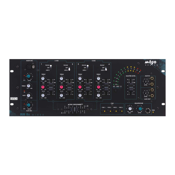
MM 8x MIXER
QUICK START
Here are a few basic "plug and play" steps to get you performing. If you are a first time DJ mixer user, please do
yourself a favor and at least read this section.
Begin by making sure your amplifier is off before making connections. The MM 8x has all unbalanced connectors,
except for the 1/4" balanced main outputs and XLR microphone inputs. Plug a source component, such as a CD player,
into one of the four LINE inputs on the rear. Connect the MAIN OUTPUTS to your amplifier. Set all front panel controls
to the middle of their travel and all pushbuttons to their out position. Slide the MASTER LEVEL down to 0. Set an
INPUT SELECT switch to your active source input. Plug in the MM 8x's power supply and see the PWR indicator
illuminate. Turn on your source and amplifier. Slowly turn up the MASTER LEVEL and see the meters lighting and hear
music from your speakers.
In use, you can get tripped up at two places. If you have a phono signal into one of the four PH/LN inputs, be sure the
PH/LN switch is in the PHONO position (in); likewise, when using a tape deck or CD into these inputs, be sure the switch
is in the LINE (out) position. If you plug into the PROGRAM LOOP, the internal signal path is broken. Be sure that a
complete loop is made, to and from an outside device.
Couldn't be easier, right?
Never connect anything except a Rane power supply to the thing that looks like a telephone jack on the rear or the
unit. This is an AC input and requires special attention if you do not have a power supply exactly like the one originally
packed with your unit. See the full explanation of the power supply requirements elsewhere in this manual.
Manual-1
Advertisement
Table of Contents

Related Manuals for Rane MM 8X


Summary of Contents for Rane MM 8X
-
Page 1: Quick Start
Couldn’t be easier, right? Never connect anything except a Rane power supply to the thing that looks like a telephone jack on the rear or the unit. This is an AC input and requires special attention if you do not have a power supply exactly like the one originally packed with your unit. -
Page 2: Front Panel Description
FRONT PANEL DESCRIPTION 1. MAIN MIC ON switch: This switch puts the Main Mic signal into the mixer signal path. When the switch is pressed in, the Main Mic is on and the adjacent red LED blinks. 2. Front panel MAIN MIC input: This 3-pin XLR input connects a balanced microphone. A parallel Main Mic input is on the rear of the unit. - Page 3 Cue signals. 21. HEADPHONE Output jack: This stereo ¼" TRS jack accepts ¼" TRS stereo headphone plugs (do not use mono plugs). 22. POWER “ON” indicator: When the yellow LED is lit, the MM 8x is ready to go. Fader Care: With heavy use in harsh environments, the faders may need lubrication.
- Page 4 2. Chassis ground point: This screw is provided for grounding purposes. This unit comes with an outboard power supply which does not ground the chassis through the line cord. The MM 8x can be grounded either to another chassis which is earth grounded, or directly to the grounding screw on an AC outlet cover with a wire connected to this chassis screw.
-
Page 5: Source Selection
SOURCE SELECTION The source faders control the level of the selected input. The MM 8x is able to mix together four sources. Each They also provide a means to set relative levels for each input source is switchable between two line inputs, one of which to A and B mixes. -
Page 6: Main Output
The active crossfader output signal is routed to the the output signal level. Program Loop jack. The signal can be fed to external effects units and returned to the MM 8x. The Program Loop return METERING signal is combined with the Microphone and Auxiliary input The MM 8x’s meter displays signal level in peak dBu. - Page 7 MOJO GLOSSARY Term meaning to insert between two points. If a graphic equalizer’s adjacent bands, when moved together, produce a smooth response without a dip in the center, they are interpolat- ing between the fixed center frequencies. bandwidth remains constant for all boost/cut levels. Since Q and bandwidth are interrelated, the terms are fully interchangeable.
-
Page 8: Sound System Interconnection
Do not be tempted to use 3-prong to Rane's web site (addresses on page Manual-12), or ask your 2-prong “cheater” adapters to lift grounds. This is a danger- dealer for a copy. - Page 9 VARIOUS XLR, RCA & ¼" CABLE ASSEMBLIES Manual-9...
- Page 10 ©Rane Corporation 10802 47th Ave. W., Mukilteo WA 98275-5098 TEL (425)355-6000 FAX (425)347-7757 WEB http://www.rane.com Manual-10 All features & specifications subject to change without notice.
Need help?
Do you have a question about the MM 8X and is the answer not in the manual?
Questions and answers