Table of Contents
Advertisement
Quick Links
Advertisement
Table of Contents

Related Manuals for Hawking HWU54G


Summary of Contents for Hawking HWU54G
-
Page 2: Limited Warranty
LIMITED WARRANTY Hawking Technology guarantees that every HWU54G Mini Wireless-G USB Network Adapter is free from physical defects in material and workmanship under normal use for two (2) years from the date of purchase. If the product proves defective during this two-year warranty period, call Hawking Customer Service in order to obtain a Return Authorization number. -
Page 3: Federal Communication Commission Interference Statement
Federal Communication Commission Interference Statement This equipment has been tested and found to comply with the limits for a Class B digital device, pursuant to Part 15 of FCC Rules. These limits are designed to provide reasonable protection against harmful interference in a residential installation. This equipment generates, uses, and can radiate radio frequency energy and, if not installed and used in accordance with the instructions, may cause harmful interference to radio communications. - Page 4 Federal Communications Commission (FCC) RF Exposure Requirements SAR compliance has been established in the laptop computer(s) configurations with PCMCIA slot on the side near the center, as tested in the application for Certification, and can be used in laptop computer(s) with substantially similar physical dimensions, construction, and electrical and RF characteristics.
-
Page 5: Table Of Contents
1 INTRODUCTION ..1 Features ...1 Specifications ...1 Package Contents ...2 2 INSTALLATION PROCEDURE ..3 3 CONFIGURATION UTILITY ... 7 General...7 3.1.1 Preference Setting ...9 3.1.2 Site Survey...9 Profiles ...10 3.2.1 Configure the Profile ...12 3.2.2 Enable WPA..14 Current Statistics ...15 About ...16 4 TROUBLESHOOTING ... -
Page 6: Introduction
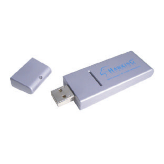
The Hawking Technologies Mini Wireless-G USB 2.0 Network Adapter is designed to be fully compliant with both IEEE 802.11b and IEEE 802.11g wireless networking standards. The HWU54G uses the latest in wireless chip technology and is capable of transferring data wirelessly at speeds up to 54 Mbps! In addition to being a high-speed wireless adapter, the Mini Wireless-G Adapter is the size of a finger. -
Page 7: Package Contents
Data Rate: 54/48/36/24/18/12/11/9/6/5.5/2/1Mbps auto fallback Security: 64/128-bit WEP Data Encryption, WPA (TKIP with IEEE 802.1x) Antenna: Internal Drivers: Windows 2000/XP LEDs: Power, LinkTransmit Power: 16 dBm Temperature: 32~131°F (0 ~55°C) Humidity: Max. 95% (NonCondensing) Certification: FCC, CE 1.3 Package Contents Before you begin the installation, please check the items of your package. -
Page 8: Installation Procedure
2 Installation Procedure Before you proceed with the installation, please notice following descriptions. Note: The following installation was performed under Window s XP. (Procedures are similar for Windows 98SE/Me/2000.) I. Install the Driver A. Insert the Installation CD into your CD-ROM driver. B. - Page 9 F. The wizard will install the driver automatically. Click “Finish” to complete the installation. II. Install the Utility A. Execute the "Utility\setup.exe" program from the installation CD. B. The InstallShield Wizard box will appear, click “Next” to continue. Choose the selection “I accept the terms in the license agreement”...
- Page 10 If you want to change the destination folder, click “Change”, or click “Next” to continue. The wizard will install the driver automatically. Click “Finish” to complete the installation. There is no different among the three-setup types. Click “Next” directly.
- Page 11 III. Using the Utility Go to Start\All Programs\Envara Configuration Utility and select “EnvaraGui”. This will load the Wireless Utility.
-
Page 12: Configuration Utility
3 Configuration Utility The Configuration Utility is a powerful application that helps you configure the adapter and monitor the link status and the statistics during the communication process. However, there are some restrictions on the utility. Before using the utility, you should study and learn them. - Page 13 Parameter Connected to (SSID) Network Mode Channel / Frequency Max. Network Rate Security Power Save Active Profile Radio Status Enable Radio Button Link Quality Received Sent Network Rate Preferences Button View Site Button Description Displays the wireless network that the adapter is connecting to. There are two network types: Infrastructure and Ad Hoc.
-
Page 14: Preference Setting
3.1.1 P r e f e r e n c e S e t t i n g This preference screen enables you to change the unit used to measure link quality or the time interval used to refresh the data. The default settings is “10” for “Statistics Update Interval” and “Percent” for “Parameter Display Units”. -
Page 15: Profiles
Parameter Connect Button Save Profile Button Edit Connect Button Rescan Button AP View/Network View Button Profiles The Profiles let you easily manage the wireless networks that your frequently connect to. Simply save the settings of the different wireless networks your frequent and select the saved profile each time you connect to them. - Page 16 Parameter Auto-Selection Profiles Additional Profiles Right Click Function List Description If a profile is set as an Auto-Selection profile the utility will attempt to automatically connect the adapter to the respective profile in the order they are listed in the Profile list. All networks that you have previously connected to will be listed.
-
Page 17: Configure The Profile
3.2.1 Configure the Profile When you click “New” or “Edit” in the Profiles page the “Profile Configuration ” screen will appear. In this screen, there are two pages: General and Security. General Parameter Name Network Name (SSID) Network Mode Power Save Channel / Frequency Description Change the name of your Profile for easier identification. - Page 18 Auto-Select Profile Member Parameter Defaults Encryption Parameter Security Use 802.1x Encryption Key (Key1 ~ Key4) If you select the check box, this profile will be put in the “Auto-Selection Profiles ” list. Description The default values are Ad Hoc mode and channel one. If you want to set up to default, click this button.
-
Page 19: Enable Wpa
3.2.2 Enable WPA Wi-Fi Protected Access (WPA) is a specification of standards -based, interoperable security enhancements that strongly increase the level of data protection (encryption) and access control (authentication) for existing and future wireless LAN systems. The technical components of WPA include Temporal Key Integrity Protocol (TKIP) for dynamic key exchange, and 802.1 x for authentication. -
Page 20: Current Statistics
Parameter Network Authentication Data Encryption Current Statistics This option enables you to view the signal strength and the statistical information of successful Tx and Rx baud rate. You may reset the counters by clicking “Reset”. The “SNR” indicates the rate of noise and signal in the environment, the bigger of the value, the better the signal strength. -
Page 21: About
About By choosing this option, you can view basic information such as the Driver, Firmware and Utility Version. And you can click the hyperlink to connect the website for the information of the wireless chipset vendor. -
Page 22: Troubleshooting
4 Troubleshooting This chapter provides solutions to problems usually encountered during the installation and operation of the adapter. 1. Why can’t the USB adapter work or only work in 11b mode while connect to USB 2.0 port? If this situation occurs, please upgrade the driver of your USB port. This problem may be the compatibility issue with the old driver of the USB port. - Page 23 6. What is Infrastructure? An integrated wireless and wireless and wired LAN is called an Infrastructure configuration. Infrastructure is applicable to enterprise scale for wireless access to central database, or wireless application for mobile workers. 7. What is BSS ID? A specific Ad hoc LAN is called a Basic Service Set (BSS).
- Page 24 receiver, DSSS appears as low power wideband noise and is rejected (ignored) by most narrowband receivers. 14. What is Spread Spectrum ? Spread Spectrum technology is a wideband radio frequency technique developed by the military for use in reliable, secure, mission-critical communication systems. It is designed to trade off bandwidth efficiency for reliability, integrity, and security.
Need help?
Do you have a question about the HWU54G and is the answer not in the manual?
Questions and answers