Table of Contents
Advertisement
Quick Links
UPS SNMP/Web Adapter
FCC Radio/TV Interference Notice
The UPS SNMP/Web Adapter Card and the External UPS SNMP/Web Adapter have been tested and found to comply with the
limits for a Class A digital device, pursuant to Part 15 of the FCC Rules. These limits are designed to provide reasonable protection
against harmful interference when the equipment is operated in a domestic environment. Both these devices generate, use and can
radiate radio frequency energy and, if not installed in accordance with the instruction manual, may cause harmful interference to
radio communications. The user must use shielded cables and connectors with these products. Any modifications to these products
not expressly approved by the party responsible for compliance could void the user's authority to operate the equipment.
Copyright 2002 Tripp Lite. All rights reserved.
Version 4.
All trademarks and trade names are the properties of their respective owners.
1111 West 35th Street
Chicago, IL 60609
Customer Support: (773) 869-1234
www.tripplite.com
U
'
G
SER
S
UIDE
i
Advertisement
Table of Contents

Related Manuals for Tripp Lite UPS SNMP/Web Adapter


Summary of Contents for Tripp Lite UPS SNMP/Web Adapter
- Page 1 FCC Radio/TV Interference Notice The UPS SNMP/Web Adapter Card and the External UPS SNMP/Web Adapter have been tested and found to comply with the limits for a Class A digital device, pursuant to Part 15 of the FCC Rules. These limits are designed to provide reasonable protection against harmful interference when the equipment is operated in a domestic environment.
-
Page 3: Table Of Contents
Terminal Mode Configuration __________________________________________________________________5 Other Terminal Mode Configuration Options _______________________________________________________________ 6 Installing the UPS Adapter in a LAN ____________________________________________________________8 To Install the UPS SNMP/Web Adapter Card_______________________________________________________________ 8 To Install the External UPS SNMP/Web Adapter____________________________________________________________ 8 Chapter 3 SNMP ______________________________________________________________________ 10... -
Page 5: Chapter 1 Introduction
Introduction Congratulations on the purchase of your new UPS SNMP/Web Adapter. Your UPS SNMP/Web Adapter will connect your UPS to your LAN. This will allow you to monitor and control the UPS from any PC on the LAN, using either: •... -
Page 6: Details - Adapter Card
SNMP Adapter User’s Guide Details - Adapter Card Figure 1:- UPS SNMP/Web Adapter Card Item Description DIP Switches. (See DIP switch table, p. 3). Red Error LED. Yellow Link LED. Humidity/Temperature Sensor Connector (PS2). 10 Base-T (UTP RJ45) Ethernet Connector. -
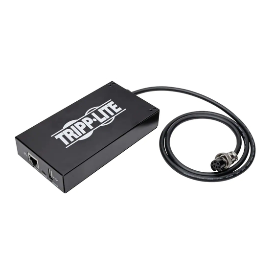
Page 7: Details - External Adapter
Introduction Details - External Adapter Figure 2:- UPS SNMP/Web External Adapter Item Description Power Connector. UPS Serial Port. Terminal Serial Port. DIP Switches. (See DIP switch table, below). LEDs. Humidity/Temperature Sensor Connector (PS2). 10 Base-T (UTP RJ45) Ethernet Connector. DIP Switch Table (Both Models) DIP Switch Table Description... -
Page 8: Package Contents
SNMP Adapter User’s Guide Package Contents The following items should be included in your package. If any items are missing, contact your dealer immediately. Adapter Card • UPS SNMP/Web Adapter Card • CD-ROM including • MIBs • Owner’s manual •... -
Page 9: Chapter 2 Configuration
Chapter 2 Configuration Your UPS Adapter can be configured for use with many different LAN setups and for many different applications. This chapter explains the procedures and settings used in UPS Adapter configuration. Selecting an IP Address You must choose an IP address for your UPS Adapter before connecting it to your network. The IP address must be unique to the UPS Adapter, and it must be in the same address block as the computer(s) it will communicate with. -
Page 10: Other Terminal Mode Configuration Options
SNMP Adapter User’s Guide Other Terminal Mode Configuration Options Besides setting the IP address of your UPS Adapter, you may use terminal mode configuration to set up other functions of the UPS Adapter. The menu options presented through terminal mode configuration are explained below. 1. - Page 11 Configuration The IP address of the Trap Host. Address Community String If the Trap Host is assigned a Community, enter it here. Otherwise, leave this field blank. Trap Ctrl Enables/disables the Adapter sending Traps to this Trap Host. Authent Enables/disables warning this Host of illegal SNMP activity, i.e.
-
Page 12: Installing The Ups Adapter In A Lan
To Install the UPS SNMP/Web Adapter Card Turn the UPS OFF. Insert the UPS SNMP/Web Adapter Card into the UPS accessory slot (see UPS manual for location.) Connect the UPS SNMP/Web Adapter Card to your LAN, using a 10 BaseT UTP connector. -
Page 14: Chapter 3 Snmp
Chapter 3 SNMP Your UPS SNMP/Web Adapter allows a UPS to be managed by SNMP tools, using the UPS SNMP Agent and the UPS SNMP MIB. The UPS SNMP Agent is in the UPS SNMP/Web Adapter’s SNMP firmware. It responds to standard SNMP commands (get, get next and set) and will generate SNMP traps (messages) if configured to do so. -
Page 15: Chapter 4 Browser Interface
Chapter 4 Browser Interface You may monitor and control a UPS system with an UPS SNMP/Web Adapter using an Internet browser. The UPS Adapter generates navigable HTML pages. The HTML pages are updated to match the UPS’s status every 30 seconds;... -
Page 16: Interface Pages
SNMP Adapter User’s Guide Interface Pages Status Page This page shows commonly useful information about the UPS: Note: A value of N/A (Not Applicable)in any of the fields indicates that your UPS model does not support that data variable. Field Definition Manufacturer The UPS’s maker. -
Page 17: Variables Page
Browser Interface Variables Page This page shows the current value of all the operating variables your UPS can communicate. Each variable is marked with one of four indicator icons: Icon Indication Normal: An operating variable within its usual range. Informational: An UPS variable that differs from model to model and does not change due to operating conditions. - Page 18 SNMP Adapter User’s Guide Different UPS models have different communication capabilities. Depending on your UPS model, the variables on the Variable Page may include some or all of the following: Variable Definition Nominal Input AC voltage the UPS is designed to accept. Voltage UPS Mode “Line”...
-
Page 19: Event Log Page
Browser Interface Contact Name Set by user on the UPS Settings page. Contact Number Set by user on the UPS Settings page. Event Log Page This page displays a list of the most events your UPS has experienced. The list’s first column, Date/Time, tells exactly when the event occurred in a Day/Month/Year Hour:Second format. The second column, System Message, gives a brief description of the event. - Page 20 SNMP Adapter User’s Guide “Save Settings” button to send your changes to the UPS Adapter. If you select the “Reboot Agent on Submit” option, the UPS Adapter will reboot using the new settings when the “Save Settings” button is pushed. SNMP Card Setup allows you to change your UPS Adapter’s network settings.
- Page 21 Browser Interface Trap Receivers Setup allows you to configure your UPS Adapter to communicate with its Trap Hosts, which will receive SNMP Traps sent by the UPS Adapter. Up to ten Trap Hosts may be assigned to the UPS Adapter. For each Trap Host, enter the following information: Trap Receivers Usage...
-
Page 22: Ups Settings Page
SNMP Adapter User’s Guide UPS Settings Page On this page you may enter information that will make it easier to identify and manage the connected UPS. The information you enter here will be displayed on the Variables page. After making changes to these settings, scroll down to the buttons at the bottom of the page. -
Page 23: Thresholds Page
Browser Interface After making changes to these settings, scroll down to the buttons at the bottom of the page. You may press the “Reset” button to clear your changes, or the “Submit” button to send your changes to the UPS Adapter. Thresholds Page This page displays a list of UPS operating variables that your Web Card monitors, showing the critical values—Thresholds—that have been set for each variable. -
Page 24: Environmental Page
Event Action (see Event Actions Page). The Warning Event will reset if the parameter returns inside the limits. Note: The conditions shown on this page are only accurate if you have connected a Tripp Lite EnviroSense device to your UPS Adapter. Parameter... -
Page 25: Chapter 5 Troubleshooting
Chapter 5 Troubleshooting This chapter covers some common problems you may encounter during the configuration and normal operation of the UPS SNMP/Web Adapter. Whenever a problem is encountered: • Make sure that the UPS SNMP/Web Adapter is turned on. •... - Page 26 SNMP Adapter User’s Guide To Connect if Your IP Address Range is Different If your current IP Address is NOT within the 192.168.x.x range, follow this procedure: • Temporarily change your PC’s IP Address so that it is within the same range as your UPS Adapter’s range. (Choose any address which is not in use.) Also, make sure the Network Mask is set to 255.255.255.0 •...
-
Page 27: Appendix A Specifications
Appendix A Specifications UPS SNMP/Web Adapter Card Intel 80186-25 Memory ROM/RAM: 512Kbytes NVRAM: 2Kbytes Power Consumption: < 4 Watts Power Input: 12 VDC regulated Size: 130mm (L) x 60mm (W) Ethernet Connector: 10 BaseT RJ-45 phone jack LEDs: DIP Switches:... - Page 28 SNMP Adapter User’s Guide Operating Temperature: 0∼40 degrees C Storage Temperature: -10∼70 degrees C Shipping Temperature: -40∼70 degrees C Operating Humidity: 10∼80 percent Storage Humidity: 5∼90 percent Shipping Humidity: 5∼100 percent...
-
Page 29: Ps/2 Connector
Appendix A - Specifications PS/2 Connector PS/2 Connector Pins Name Description Ground +9V or Power +12V Not used Not used Serial transmit Serial receive Serial Port – Adapter Card Figure 3:- Pin Assignments Name Description +12V GND +12V +12V Power RXDUPS Connect to UPS Tx signal TXDUPS... -
Page 30: Serial Port - External Adapter
SNMP Adapter User’s Guide Serial Port – External Adapter Signal Name Type Carrier Detect (CD) Receive (Rx) Transmit (Tx) Data Terminal Ready Signal Ground (GND) Power Data Set Ready (DSR) Request to Send (RTS) Clear to Send (CTS) Ring Indicator (RI) 93-1925 (200206080)
Need help?
Do you have a question about the UPS SNMP/Web Adapter and is the answer not in the manual?
Questions and answers