Table of Contents
Advertisement
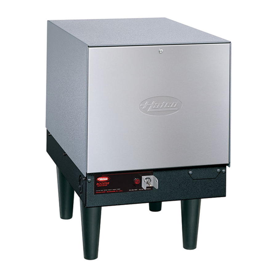
Electric Booster Water Heaters
This manual contains important safety information
concerning the maintenance, use and operation of this
product. Failure to follow the instructions contained in this
manual may result in serious injury. If you're unable to
understand the contents of this manual, please bring it to
the attention of your supervisor. Do not operate this
equipment unless you have read and understood the
contents of this manual.
Imperial "S"
Compact "C"
Mini-Compact "MC"
Series
Installation &
Operating Manual
I&W #07.05.001.00
Este manual contiene importante información sobre
seguridad concerniente al mantenimiento, uso y
operación de este producto. Cualquier falla en el
seguimiento de las instrucciones contenidas en este
manual puede resultar en un serio daño. Si usted no
puede entender el contenido de este manual por
favor pregunte a su supervisor. No opere este
equipo al menos que haya leído y comprendido el
contenido de este manual.
Advertisement
Table of Contents

Related Manuals for Hatco IMPERIAL "S"


Summary of Contents for Hatco IMPERIAL "S"
- Page 1 Electric Booster Water Heaters Operating Manual This manual contains important safety information concerning the maintenance, use and operation of this product. Failure to follow the instructions contained in this manual may result in serious injury. If you’re unable to understand the contents of this manual, please bring it to the attention of your supervisor.
-
Page 2: Table Of Contents
Health Codes, NSF Standard #5 and plumbing codes. All Hatco Booster Heaters are ready for electrical and plumbing service connections, with a pre-set ambient compensated immersion thermostat(s) and a high temperature limit switch. The service area is accessible from the front of the unit, permitting easy installation. -
Page 3: Important Safety Information
IMPORTANT SAFETY INFORMATION Hatco has always endorsed the use of safety equipment when using a booster water heater or storage-type water heater. Hatco booster heaters temperature/pressure relief valve at no extra charge. - Page 4 Some aftermarket or generic replacement parts do not have the characteristics that will allow them to operate safely in Hatco equipment. It is essential to use Hatco Replacement Parts when repairing Hatco equipment. Failure to...
- Page 5 70°F (21°C). CAUTIONS Hatco requires that two temperature/pressure gauges, Hatco part number 03.01.003.00, be installed to assure proper operation. Install one in the supply line before the pressure reducing valve and one in the outlet line as close to the booster heater as possible.
-
Page 6: Model Description
MODEL DESCRIPTIONS ALL MODELS Hatco Electric Water Booster Heaters are available in three models: Imperial, Compact and Mini- Compact. All standard models include a booster heater with low-water cut-off system, temperature/pressure relief valve, pressure reducing valve with built-in high pressure bypass, two temperature/pressure gauges and a high temperature limit safety switch. -
Page 7: Specifications
CIRCUIT BREAKER & FUSED DISCONNECT SWITCH SIZES - 4 TO 12 kW Volts* Phase 10.4 10.5 11.4 Wire size is based on THHN wire for branch circuit protection at .91 derate factor. Circuit breakers and fused disconnects are to be mounted remote and wired by contractor. Sizes are based on the 2002 NEC table 310-16. - Page 8 SPECIFICATIONS CIRCUIT BREAKER & FUSED DISCONNECT SWITCH SIZES - 13.5 TO 30 kW Volts* Phase 13.5 17.25 Wire size is based on THHN wire for branch circuit protection at .91 derate factor. Circuit breakers and fused disconnects are to be mounted remote and wired by contractor. Sizes are based on the 2002 NEC table 310-16.
- Page 9 CIRCUIT BREAKER & FUSED DISCONNECT SWITCH SIZES - 36 to 57 kW Volts* Phase 40.5 Wire size is based on THHN wire for branch circuit protection at .91 derate factor. Circuit breakers and fused disconnects are to be mounted remote and wired by contractor. Sizes are based on the 2002 NEC table 310-16.
-
Page 10: Sizing Chart For Low-Temp Dishmachines
SPECIFICATIONS SIZING CHART FOR LOW-TEMP DISHMACHINES BOOSTERS RATED AT 30°F (16°C) RISE Dishwasher Model Number American Dish AH, AH-3D, AH-3D-S, AHC, AHC-3D, AHC-3D-S, ET-A, ET-AF, ET-AH, Service ET-A-M, ET-AH-M, ET-A-3, ET-AH-3, L-90-3D, L-90-3D-K, L-90-3D-K-S, L-90-3D-S, L-90-3DC, L-90-3DC-K, L-90-3DC-K-S, L-90-3DC-S, L-90-3DW, L-90-3DW-K, L-90-3DW-K-S, L-90-3DW-S, L-90-3DWC, L-90-3DWC-K, L-90-3DWC-K-S, L-90-3DWC-S, WH, WHC . - Page 11 SIZING CHART FOR LOW-TEMP DISHMACHINES (CONTINUED) BOOSTERS RATED AT 30°F (16°C) RISE Dishwasher Model Number Jackson Conserver 24LT, 200LT, ES1000, (Ecolab/Jackson) ......C-4 ..S-6 Conserver 1, Conserver XL, ES2000 (Ecolab/Jackson) .
-
Page 12: Booster Heater Sizing Chart
SPECIFICATIONS BOOSTER HEATER SIZING CHART Dishwasher Model Number Adamation CSL-1390, CA-2, CA-3, CA-4, SLAP 44 ....C-39 ..(2)C-36 ..S-39 ..(2)S-36 CA, CA-1 . - Page 13 BOOSTER HEATER SIZING CHART (CONTINUED) Dishwasher Model Number Dishmachines CMA-180 ......... .C-7 ..C-12 ..S-7 ..S-12 CMA-44H with tank heater, CMA-66H .
- Page 14 SPECIFICATIONS BOOSTER HEATER SIZING CHART (CONTINUED) Dishwasher Model Number Jackson JP-24, JP-24B, JP-24F, JP-24BF ......C-4 ..C-6 ..S-6 ..S-6 24B Series .
- Page 15 Foundation. Where make-up water for wash tank is provided from final rinse supply, chart recommendations are based upon this additional demand (not over 2 GPM) as required by NSF. All sizings shown are that of the dishwasher manufacturers. Hatco Corporation is not responsible for incorrect sizing applications.
-
Page 16: Capacity Charts
SPECIFICATIONS Model S-12 S-13 13.5 S-15 S-17 17.2 S-18 S-24 S-27 S-30 S-36 S-39 S-40 40.5 S-45 S-54 S-57 Storage capacity is 16 gallons (61 liters). CAPACITY - COMPACT “C” SERIES Model C-12 C-13 13.5 C-15 C-17 17.2 C-18 C-24 C-27 C-30 C-36... -
Page 17: Dimensions
SPECIFICATIONS DIMENSIONS - IMPERIAL “S” SERIES DIMENSIONS - COMPACT “C” SERIES 4 to 18 kW DIMENSIONS - COMPACT “C” SERIES 24 to 57 kW Form No. EBOOSTERM-0406... -
Page 18: Installation
SPECIFICATIONS DIMENSIONS - MINI-COMPACT “MC” SERIES INSTALLATION LOCATION For the most effective operation, install the booster heater as close as possible to the commercial dishwasher. The location must have a solid foundation along with being clean and dry. Adequate front clearance is required to allow for accessibility to the control compartment. -
Page 19: All Models
To avoid personal injury or damage to the equipment, follow standard welding procedures when attaching sliderails to bottom of dishtable. 6. Using Hatco slide brackets as a template, drill 1/8" (3 mm) holes into the sides of the heater jacket. - Page 20 INSTALLATION One set of four legs supplied with all Imperial and Mini- Compact Booster Heaters. (All Compact 4-57 kW units supplied with either a set of legs or mounting brackets.) Plastic leg, Part No. 05.30.069.00 Stainless Steel, Part No. 05.30.070.00 Mounting Brackets with Hardware A set of mounting brackets or a set of legs supplied with each Compact 4-57 kW booster heater.
-
Page 21: Pressure & Temperature Relief Valves
WARNING Valves supplied by Hatco are designed for high temperature commercial operation. Do not substitute Hatco valves with valves designed for domestic water heaters. -
Page 22: Pressure Reducing Valve
PRESSURE REDUCING VALVE CAUTION If water supply pressure to the booster inlet is over 20 psi (138 kPa) during flow, install Hatco pressure reducing valve with built-in bypass, Hatco part number 03.02.004.00, for proper operation of dishwater rinse nozzles. - Page 23 Refer to Figure 8, 9, 10, 11 or 12. 1. Connect the booster water inlet to a hot water supply line from the regular water heater. Water temperature from the regular water heater should be 110° or 140°F (43° or 60°C) and should not exceed 160°F (71°C).
- Page 24 Bypass 20 psi (138 kPa) flow pressure maximum 3/4" Gate or Ball Valve Water Inlet from primary water heater Blended Phosphate Water Treatment System† NOTE: Centerline of booster “T” fitting must not extend closer than 4" (102 mm) to the floor.
- Page 25 Bypass 20 psi (138 kPa) flow pressure maximum Temperature/Pressure Gauge 3/4" Gate or Ball Valve Water Inlet from primary water heater Blended Phosphate Water Treatment System† Discharge from T/P Relief Valve. Air gap † optional accessory must comply with plumbing code.
- Page 26 Figure 15. Alternate Temperature/Pressure Gauge Installation WARNING Hatco has always endorsed the use of safety equipment when using a booster water heater or storage-type water heater. Hatco booster heaters are shipped with a temperature/pressure relief valve at no extra charge. This valve must be installed into the marked opening provided in the tank.
-
Page 27: Electrical Connections
ELECTRICAL-ALL SIZES AND VOLTAGES General Hatco Electric Booster Water Heaters are available for operation on standard power systems. Check the identification decal for the proper power supply. CAUTION To assure proper performance Hatco Electric Booster Water Heaters are only to be connected to the same power supply as indicated on the specification decal. -
Page 28: Operation
Limit Safety Switch that will shut the power off if the unit overheats. To avoid any injury to personnel or damage to the unit, contact an Authorized Hatco Service Agent if the High Temperature Limit Safety Switch cannot be reset or continues to trip. -
Page 29: Thermostat Adjustment
NOTE: 1/6 turn of the inner screw equals 8°F (4.4°C). HIGH TEMPERATURE LIMIT SAFETY SWITCH All Hatco Electric Booster Water Heaters are equipped with a manually reset high temperature limit safety switch. If the temperature of the water in the heater exceeds 210°F (99°C) the safety switch will shut off the power. - Page 30 Some aftermarket or generic replacement characteristics that will allow them to operate safely in Hatco equipment. It is essential to use Hatco Replacement Parts when repairing Hatco equipment. Failure to use Hatco Replacement Parts may subject operators of the equipment to hazardous electrical voltage, resulting in electrical shock or burn.
-
Page 31: Shock Absorber
STAINLESS STEEL ADJUSTABLE LEGS 1. Carefully place unit on its side. CAUTION Do not lay unit on the side with the control panel or damage to unit could occur. 2. Thread the adjustable legs into the existing leg holes on the bottom of the unit. (See Figure 21.) 3. -
Page 32: Troubleshooting
6. The breakers or fuses MUST be properly sized. 7. Be sure that the temperature/pressure relief valve is one supplied by Hatco and properly installed. 8. A check valve should not be installed ahead of the booster. - Page 33 WARNING To avoid any injury or damage, the booster heater must only be serviced by qualified personnel. SYMPTOM Water reaches 180°F (82°C) but does not last through the entire dishwasher operation. The booster heater does not heat at all or only delivers water at 120°-150°F (49°-66°C).
- Page 34 Remove check valve or anti-siphon valve to allow for water expansion or install a back pressure relief valve on the incoming water line, Hatco part number 03.02.039.00. Thermostat may be set too high or is sticking. Recalibrate (page 27) or replace the thermostat.
- Page 35 WARNING To avoid any injury or damage, the booster heater must only be serviced by qualified personnel. SYMPTOM High temperature limit trips. Chattering contactor or low water cutoff circuit board. To avoid any injury or damage to the booster heater turn the power OFF at the disconnect switch/circuit breaker and allow to cool before performing any maintenance.
-
Page 36: Hatco Limited Warranty
Hatco reserves the right to accept or reject any such claim in whole or in part. Hatco will not accept the return of any Product without prior written approval from Hatco, and all such approved returns shall be made at Buyer’s sole expense. - Page 37 NOTES Form No. EBOOSTERM-0406...
- Page 38 NOTES Form No. EBOOSTERM-0406...
- Page 39 NOTES Form No. EBOOSTERM-0406...
-
Page 40: Authorized Parts Distributors
Jay Hill Repair Fairfield Service Plus Flanders P.O. Box 340500, Milwaukee, WI 53234-0500 U.S.A. Parts & Service Fax (800) 690-2966 Printed in U.S.A. April 2006 HATCO AUTHORIZED PARTS DISTRIBUTORS NEW YORK Acme American Repairs, Inc. 317-545-9655 Brooklyn Alpro Service Co. Brooklyn...
Need help?
Do you have a question about the IMPERIAL "S" and is the answer not in the manual?
Questions and answers