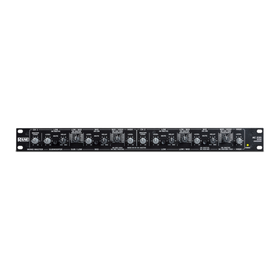
Rane AC 23S Operator's Manual
Active crossover
Hide thumbs
Also See for AC 23S:
- User manual (84 pages) ,
- Datasheet (4 pages) ,
- Operator's manual (7 pages)

Related Manuals for Rane AC 23S


Summary of Contents for Rane AC 23S
- Page 1 AC 23 ACTIVE CROSSOVER...
-
Page 2: Important Safety Instructions
• Connect the equipment into an outlet on a circuit different from that to which the receiver is connected. • Consult the dealer or an experienced radio/TV technician for help. CAUTION: Changes or modifications not expressly approved by Rane Corporation could void the user's authority to operate the equipment. This Class B digital apparatus complies with Canadian ICES-003. -
Page 3: Quick Start
LOW OUT, now go back to MID OUT, then Set the STEREO/MONO switch appropriately. The fact that over to HIGH-MID OUT and then proceed to the HIGH the AC 23S is a multiple function unit means the outputs are OUT. switched around in Mono mode. - Page 4 1.0k LEVEL LEVEL LEVEL DELAY LEVEL DELAY 1.0k LEVEL MUTE MUTE 2.0k MUTE MUTE 2.0k AC 23S 2.8k 2.8k 4.5k 4.5k ACTIVE 5.8k 5.8k CROSSOVER 7.0k 7.0k 4W: MID / HIGH MONO 4W OR 5W: INACTIVE 4W: INACTIVE 4W: INACTIVE...
- Page 5 REAR PANEL: STEREO 2-WAY CONNECTIONS Stereo 2-way connection labels are in this row Right Input Left Input AC 23S HIGH OUT 3W: MID OUT 3W: LOW OUT CHANNEL 2 IN STEREO 3W / 2W HIGH OUT 3W: MID OUT 3W: LOW OUT...
- Page 6 1.0k LEVEL LEVEL LEVEL DELAY LEVEL DELAY 1.0k LEVEL MUTE MUTE 2.0k MUTE MUTE 2.0k AC 23S 2.8k 2.8k 4.5k 4.5k ACTIVE 5.8k 5.8k CROSSOVER 7.0k 7.0k 4W: MID / HIGH MONO 4W OR 5W: INACTIVE 4W: INACTIVE 4W: INACTIVE...
- Page 7 REAR PANEL: STEREO 3-WAY CONNECTIONS Stereo 3-way connection labels are in this row Right Input Left Input AC 23S HIGH OUT 3W: MID OUT 3W: LOW OUT CHANNEL 2 IN STEREO 3W / 2W HIGH OUT 3W: MID OUT 3W: LOW OUT...
- Page 8 The HIGH-MID LEVEL control, HIGH-MID MUTE switch, HIGH-MID DELAY control and HIGH-MID / HIGH FREQUENCY control will have no effect regardless of their settings when the AC 23S is switched to “MONO 4-Way” on the back panel. r HlGH‑MID LEVEL control (5‑way only): Sets the Level of signal going to the High-Mid Output.
- Page 9 5 HlGH‑MID OUTPUT (FOR MONO 5‑WAY ONLY): Use this Output only for Mono 5-Way applications. Connect the HIGH-MID OUT to the input of the high-mid frequency amplifier. Do not use this Output when using the AC 23S as a Mono 4-Way Crossover.
- Page 10 Mid Amp Sub Amp The switching in the AC 23S will result in a Mono 4‑Way configuration with the crossover ranges SUB, LOW, MID & HIGH from left to right across the bottom front panel. By connecting a patch cable from the CHANNEL 1 HIGH OUT to the CHANNEL 2 INPUT, the LOW / MID crossover range changes from 70 Hz‑1 kHz to a higher range of 190 Hz‑7 kHz.
- Page 11 “lobe” or dispersion pattern gets tilted (usually upward) toward the driver that is further 1. The AC 23S possesses 24 dB/octave roll-off, so the crossover behind. This gets hard to put up with, because the end result is...
- Page 12 The built-in delay system in the mixer or wherever is convenient). Turn up the crossover MAS- AC 23S is designed to accommodate the majority of TER LEVEL control and the MID OUT control until noise common speaker configurations; if you encounter confu- sion or difficulty with your particular system, it is best to is heard only from the mid driver at a comfortable volume.
- Page 13 The built-in delay system 2. Position the SPL meter mic about 15 feet in front of the speak- in the AC 23S is designed to accommodate the majority ers and at a height about midway between the high and mid of common speaker configurations;...
- Page 14 Delay vs. Frequency Table In order to phase-align two drivers you must observe only If you do not have the equipment necessary to electronically the crossover frequency, which is common to both drivers. Pink align the system as described in previous sections, you may use noise can be used if all other frequencies are disregarded, since the table below to obtain a rough and approximate phase align- room acoustics and imperfect driver response will cause errone-...
- Page 15 Setting the Output Level Controls Setting Levels Using a Realtime Analyzer Choosing the crossover frequencies was the easy part. Now it gets real fun. The idea is to set the output Level controls on NOTE: If you are running two Channels, tune up only one Chan- the crossover so that the entire speaker system has a uniform, nel at a time.
- Page 16 9. Once the HIGH LEVEL control is set for 0 dB on the meter, disengage all of the MUTE switches on the crossover, and The MUTE switches on the AC 23S make using an SPL meter check that noise is emitting from all the speaker components.
- Page 17 .0056 µf 3.0 kHz .0047 µf 3.7 kHz .0039 µf 4.0 kHz .0036 µf 5.0 kHz .0030 µf 6.0 kHz .0024 µf ©Rane Corporation 10802 47th Ave. W., Mukilteo WA 98275-5000 USA TEL 425-355-6000 FAX 425-347-7757 WEB www.rane.com Manual-15 DOC 110953...
Need help?
Do you have a question about the AC 23S and is the answer not in the manual?
Questions and answers