Rane AC 23B Operator's Manual
Active crossover
Hide thumbs
Also See for AC 23B:
- Datasheet (4 pages) ,
- Operator's manual (16 pages) ,
- Datasheet (4 pages)
Advertisement
Quick Links
QUICK START
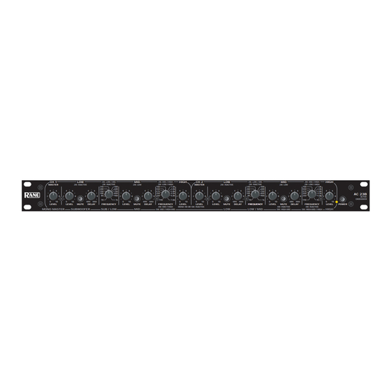
Labels above the controls refer to the unit being operated in the 2- or 3-Way Stereo mode. Labels below the
controls refer to the unit being operated in the 4- or 5-Way Mono mode.
The AC 23B is a fully balanced version of the popular AC 23 and is equipped with 3-pin (XLR-type) connectors instead
of the standard ¼" TRS jacks. A STEREO/MONO switch has been added to the AC 23B and should be set appropriately.
Switching jacks are not provided. All other specifications and operation are identical.
To operate the unit in Stereo 3-Way mode, be sure the rear panel switches are set for STEREO 3-WAY. Following the
labels above the controls and jacks in logical order, you will find CHANNEL 1 INPUT, LOW OUT, MID OUT, and HIGH
OUT, with the same for CHANNEL 2. The fact that the AC 23B is a multiple function unit means the outputs are switched
around in Mono mode. To use the unit as a Mono 5-Way, first check that the CHANNEL 1 and 2 switches are set to 3-
WAY, and the other switch is set to MONO. Connect the INPUT source to CHANNEL 1 only. Following the labels below
the jacks, look at SUB OUT, then look over at LOW OUT, now go back to MID OUT, then over to HI MID OUT and then
proceed to the HIGH OUT. An internal jumper determines 4 or 5-Way mode. Our apologies to 4-Way users: We must ship
the units in the 5-Way mode since normal Stereo 3-Way operation demands it: a fact not the least bit obvious, but neverthe-
less, a fact it remains. Pity. See page Manual-6 for Mono 4-Way configuration.
CAUTION: Never connect anything except an approved Rane Power supply to the thing that looks like a red tele-
phone jack on the rear of the AC 23B. This is an 18 VAC center tapped power input. Consult the Rane factory for a
replacement or substitution.
AC 23B CONNECTION
In agreement with IEC and AES/ANSI standards, AC 23B
wiring convention is pin 2 Positive, pin 3 Negative (return),
pin 1 Signal ground (for unbalanced use), with the connector
case or shell tied to chassis ground.
Balanced Operation
Use only when driving from a true balanced source and
driving to a true balanced destination—either transformer
coupled or active drive. Connect the input to pins 2 and 3 with
pin 2 positive. Do not connect pin 1. Terminate the shield to
the case or shell. Connect the output to pins 2 and 3 with pin
2 positive. Do not connect pin 1. Connect the shield to the
case or shell.
WEAR PARTS: This product contains no wear parts.
OPERATORS MANUAL
ACTIVE CROSSOVER
Unbalanced Operation
Connect the input between pins 2 and 1 with pin 2
positive and pin 1 Signal ground. Short pin 3 to pin 1.
Terminate the shield to the case or shell. Connect the output
between pins 2 and 1 with pin 2 Positive. Leave pin 3 open—
do not short it to pin 1. Connect the shield to the case or shell.
Combination Operation
For combined balanced and unbalanced operation, use
whichever half of the above instructions apply for each end.
See the "Sound System Interconnection" RaneNote
included with this manual for more information on cabling
and grounding requirements.
AC 23B
Manual-1
Advertisement

Related Manuals for Rane AC 23B


Summary of Contents for Rane AC 23B
- Page 1 CAUTION: Never connect anything except an approved Rane Power supply to the thing that looks like a red tele- phone jack on the rear of the AC 23B. This is an 18 VAC center tapped power input. Consult the Rane factory for a replacement or substitution.
- Page 2 Observe the labels screened above the controls for stereo operation. NOTE: In the 2-Way mode, the AC 23B crossover range is from 190 Hz to 7 kHz. The model AC 22 crossover in stereo 2-Way mode is recommended when the crossover point needs to be outside of this range.
- Page 3 REAR PANEL: STEREO 2-WAY INSTALLATION Observe the labels above the Inputs and Outputs for Stereo operation. CHANNEL 1 INPUT: Plug the left output of the mixer, equalizer or other signal source to this Input. See ‘AC 23B Connection’ on page Manual-1 for wiring details.
- Page 4 FRONT PANEL: STEREO 3-WAY CONFIGURATION Observe the labels screened above the controls for stereo operation. POWER switch: Two guesses. POWER indicator: When this yellow LED is lit, the unit is ready to operate. CHANNEL 1 MASTER LEVEL control: Sets the overall Level of Channel 1 without altering the relative settings of the Low/Mid/High frequency Outputs.
- Page 5 Observe the labels above the Inputs and Outputs for Stereo operation. CHANNEL 1 INPUT: Plug the left output of the mixer, equalizer or other signal source to this Input. Refer to ‘AC 23B Connection’ on page Manual-1 for wiring details.
- Page 6 * NOTE: Both the CHANNEL 1 HIGH LEVEL control and CHANNEL 2 MASTER LEVEL control are automatically bypassed when the AC 23B is switched to "MONO" on the back panel. Adjusting these controls has no effect in the Mono mode.
-
Page 7: Chassis Grounding
2. If your equipment is in a rack, verify that all chassis 4. Replace the cover. The AC 23B is now set for Mono 4- are tied to a good earth ground, either through the line Way Mode. - Page 8 Hl MID FREQUENCY OUTPUT (FOR MONO 5-WAY ONLY): Use this Output only for Mono 5-Way applications. Omit this output when using the AC 23B as a Mono 4-Way Crossover. Mono 4-Way Jumper Instructions are on the previous page. In 4-Way the AC 23 internally bypasses the Hi Mid section and defeats all front panel Hi Mid Controls. For Mono 5-Way connect the HI MID OUT to the input of the hi mid frequency amp.
- Page 9 2-WAY/3-WAY switches: Converts each channels outputs from 3-Way to 2-Way. For this configuration, set CHANNEL 1 to 3-Way, and CHANNEL 2 to 2-Way. POWER input connector. Use only a model RS 1 or other power supply approved by Rane. This unit is supplied with a remote power supply suitable for connection to this input jack.
- Page 10 “Linkwitz-Riley Crossovers” RaneNote. Ask your dealer, certain safety margin to accommodate more gentle filter call us here at the factory, or download it from Rane's web roll-offs and resultant higher output beyond the recommended site.
- Page 11 Some references will be made to the Rane RA 27 the MID DELAY control at minimum. realtime analyzer for those with the intelligence and good taste to use one of these regularly.
- Page 12 The built-in driver to electronically move backward until the SPL meter delay system in the AC 23B is designed to accommo- reads +3 dB; then the two drivers are electronically aligned date the majority of common speaker configurations;...
- Page 13 The built-in delay system in the AC 23B is designed to accommodate the majority of common speaker configurations; if you encounter confusion or difficulty with your particular system, it is best to consult your dealer or the Rane factory for assistance.
- Page 14 Delay vs. Frequency Table In order to phase-align two drivers you must observe only the crossover frequency, which is common to both drivers. If you do not have the equipment necessary to electroni- Pink noise can be used if all other frequencies are disre- cally align the system as described in previous sections, you garded, since room acoustics and imperfect driver response may use the table below to obtain a rough and approximate...
- Page 15 6. Adjust the display controls on the analyzer so that it shows the hands of an expert. This does require experience, skill, the greatest number of 0 dB LED’s (green on Rane and the right equipment to back it up (not to mention a equipment) below the crossover point.
- Page 16 Meter & Pink Noise Generator possible that you may turn one of the frequency section The MUTE switches on the AC 23B make using an SPL output LEVEL controls all the way up and still not have meter an easy and relatively accurate means of tuning a enough volume for a 0 dB reading (as determined by system.
-
Page 17: Channel One
CHANNEL TWO: Modification 1. Refer to the board layout on page Schematics-1. There are modification jumpers inside the AC 23B. These 2. Behind the Channel 2 LF DELAY pot find the jumper jumpers permit the transplanting of the Delay circuits from labeled W44. - Page 18 The Low Frequency Outputs are now summed. 3.0 kHz .001 µf 3.7 kHz 820 pf 4.0 kHz 750 pf 5.0 kHz 620 pf 6.4 kHz 470 pf ©Rane Corporation 10802 47th Ave. W., Mukilteo WA 98275-5098 TEL (425)355-6000 FAX (425)347-7757 WEB http://www.rane.com Manual-18 103045...
Need help?
Do you have a question about the AC 23B and is the answer not in the manual?
Questions and answers