Table of Contents
Advertisement
Quick Links
LOW
100
80
125
63
160
50
200
40
250
CHANNEL
MUTE
31.5
315
Hz
A
FREQ
0
10 ms
DELAY
-64
0
INPUT
LIMIT
LINK
OL
0
10
0
10
LEVEL
LEVEL
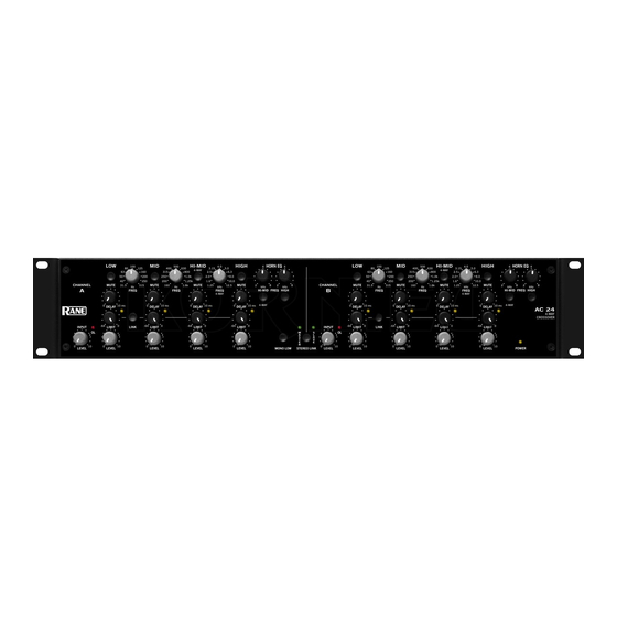
QUICK START
The AC 24 is fully balanced with XLR connectors wired pin 2
"hot" per AES standards. Set the 3-WAY/4-WAY switch on the
rear appropriately. When in 3-WAY mode, the HI-MID controls
are inactive. The MID / HI-MID Frequency control becomes the
MID / HIGH Frequency control.
If you need a summed Mono Low Ouput, push the MONO
LOW switch on the front panel.
The FREQUENCY controls and other alignment procedures
are best set with a realtime analyzer (RTA). It's also good to have
range specifications for the drivers used in the system. See Select
Crossover Frequencies on page Manual-4.
The DELAY controls add from 0 to 10 ms of signal delay to
each Output to assist in signal-aligning drivers. See Adjust Signal
Delay on page Manual-5.
CD HORN EQ is provided if constant-directivity horns are
used. If CD Horn EQ is not required, make sure the HORN EQ
filters are off (button out) and frequency settings are at 8 kHz. See
Set Cd Horn Eqs on page Manual-8.
LEVEL controls are best set using the steps provided in Set
Output Levels on page Manual-8.
The MID, HI-MID and HIGH Output LIMIT Threshold
controls are linked to preserve spectral balance. Any Output that
WEAR PARTS: This product contains no wear parts.
OPERATORS MANUAL
MID
HI-MID
HIGH
500
4.0
400
630
3.15
5.0
4-WAY
315
800
2.5
6.3
250
1.0k
2.0
8.0
200
1.25k
1.6
10.0
MUTE
MUTE
MUTE
160
1.6k
1.25
12.5
Hz
kHz
FREQ
FREQ
4-WAY
0
10 ms
0
10 ms
0
10 ms
DELAY
DELAY
DELAY
-64
0
-64
0
-64
0
LIMIT
LIMIT
LIMIT
0
10
0
10
0
10
LEVEL
LEVEL
LEVEL
HORN EQ
LOW
4
4
CHANNEL
MUTE
2
8
2
8
kHz
kHz
B
HI-MID
FREQ
HIGH
4-WAY
0
10 ms
DELAY
-64
0
INPUT
LIMIT
OL
M
S
A
L
S
A
T
V
E
E
R
0
10
0
10
MONO LOW
STEREO LINK
LEVEL
LEVEL
crosses its threshold (indicated by the indicator) will cause all
Outputs to Limit. The LOW Output is independent, and may be
linked to the others via the LIMIT LINK switch. See Set Limit-
ers on page Manual-9.
When using STEREO LINK, we recommend turning down
the Output Level controls of the SLAVE (Channel B) to mini-
mum. This prevents unwelcome surprises if the Master / Slave
function is turned off.
The SUM Outputs are useful for instrumentation devices as
indicated in the setup procedure. These may also be used for split-
band EQ and/or split-band Limiter applications. When using
these, it is important to note that CD HORN EQ and DELAYS
affect the Summed Output. If you want a flat response, do not use
Delay or CD Horn EQ when using the Sum Outputs.
The INVERT switches located on the rear panel allow you
to correct driver polarity differences without rewiring. Linkwitz-
Riley filter outputs are always in phase with correct polarity.
In agreement with IEC and AES/ANSI standards, wir-
ing convention is pin 2 positive, pin 3 negative (return), pin 1
shield chassis ground. See the "Sound System Interconnection"
RaneNote included with this manual for more information on
cabling and grounding requirements.
ACTIVE CROSSOVER
MID
HI-MID
100
500
4.0
80
125
400
630
3.15
5.0
4-WAY
63
160
315
800
2.5
6.3
50
200
250
1.0k
2.0
40
250
200
1.25k
1.6
10.0
MUTE
MUTE
31.5
315
160
1.6k
1.25
12.5
Hz
Hz
kHz
FREQ
FREQ
FREQ
4-WAY
0
10 ms
0
10 ms
DELAY
DELAY
-64
0
-64
0
LINK
LIMIT
LIMIT
0
10
0
10
LEVEL
LEVEL
AC 24
HIGH
HORN EQ
4
4
8.0
MUTE
2
8
2
8
kHz
kHz
HI-MID
FREQ
HIGH
4-WAY
0
10 ms
DELAY
AC 24
4-WAY
CROSSOVER
-64
0
LIMIT
0
10
LEVEL
POWER
Manual-1
Advertisement
Table of Contents

Related Manuals for Rane AC 24


Summary of Contents for Rane AC 24
-
Page 1: Quick Start
LEVEL POWER QUICK START The AC 24 is fully balanced with XLR connectors wired pin 2 crosses its threshold (indicated by the indicator) will cause all “hot” per AES standards. Set the 3-WAY/4-WAY switch on the Outputs to Limit. The LOW Output is independent, and may be linked to the others via the LIMIT LINK switch. - Page 2 5 Hi-Mid Output CD HORN EQ and engage switches: When the switch is pressed to the in position, the CD Horn EQ is active when the AC 24 is in 4-Way mode. If CD Horn EQ is not required, make sure the HORN EQ filters are off and frequency settings are at 8 kHz.
- Page 3 Be sure the amplifiers are off before changing any of these switches. 0 Power connector: Uses the standard cord provided. Inside the AC 24 is a universal internal switching power supply that accepts 100 to 240 VAC at 50 to 60 Hz, allowing it to work in most countries.
-
Page 4: Setup Instructions
The AC 24 possesses 24 dB per octave roll-off, so the cross- as outlined in Signal Delay Method One. Ideally, using true over points are easily set with the accuracy required to avoid delay in combination with phase compensated crossover filters, hazard to the driver or degradation in sound quality. - Page 5 Adjust the LOW / MID Frequency to just light the –6 dB red LED closest to the desired crossover • The AC 24 provides 10 ms of delay. Each dot on the silkscreen represents 1 ms or 13.57 inches (at 72 °F).
- Page 6 Set the reference level for the Mid Output: 10 ms POSITION 1 i) UnMUTE the Mid Output. ii) Adjust AC 24 Mid Output Level so the RTA LED, HI-MID = 0 ms DELAY associated with the Mid / Hi-Mid crossover frequency, 10 ms is green.
- Page 7 The in the Low frequency passband. AC 24 has independent CD Horn EQ circuits for Hi-Mid and c. MUTE the Low Output. High Outputs. It is important to know the 3 dB down point of the CD Horn driver’s frequency response.
- Page 8 You’ll wonder how you man- rating (P aged without one. c. SPL = dB SPL + [10*Log(P ©Rane Corporation 10802 47th Ave. W., Mukilteo WA 98275-5098 USA TEL 425-355-6000 FAX 425-347-7757 WEB www.rane.com Manual-8 106220...
Need help?
Do you have a question about the AC 24 and is the answer not in the manual?
Questions and answers