Table of Contents
Advertisement
Quick Links
Advertisement
Table of Contents

Related Manuals for EAW NTS250


Summary of Contents for EAW NTS250
- Page 1 N T S 2 5 0 L O U D S P E A K E R O W N E R ’ S M A N U A L...
-
Page 3: Safety Precautions - Read This First
NTS250 Loudspeaker Owner’s Manual Congratulations on the purchase of your new EAW loudspeaker. You now own one of the finest professional audio products available - the result of exceptional engineering and meticulous craftsmanship. Please read these instructions to get the maximum performance from your new loudspeaker. -
Page 4: Sicherheitshinweise - Lesen Sie Diesen Abschnitt Zuerst
Lea y observe todos los avisos e instrucciones de seguridad que aparecen en el "Manual de altavoces EAW" adjunto antes de usar este aparato. El no observar esta precaución puede dar lugar a averías en el aparato, daños en las personas o incluso la muerte. -
Page 5: Ec Declaration Of Conformity
Eastern Acoustic Works -- USA Declares that the following product(s) have been tested and passed all relevant requirements as described below by the appropriate European Directives as they apply to Professional Audio Products. Product Model: NTS250 Product Description: Self-powered loudspeaker Safety Directive(s):... -
Page 6: Table Of Contents
Contacting EAW ........ -
Page 7: Contents
230 V - Neutrik PowerCon to male Schuko plug 8 ft / 2.5 m Power Cord AC Loop (Neutrik PowerCon to Neutrik PowerCon) USB Cable 6 ft / 2 m NTS250 Owner’s Manual (this document) EAW Loudspeaker Owner’s Manual Warranty Card RJ45 Ethernet Cable 4 ft / 0.6 m (Neutrik®... -
Page 8: Quick Start
AC Mains Input: Connect to AC mains supply as labeled. AC Mains Loop Through Loop AC mains to four (4) additional NTS250 (1440 W MAX) AC Loop Circuit Breaker User resettable, 10 A (115 V), 5 A (230 V) Enable/Standby Contacts... -
Page 9: Initial Control Settings
3.1.1 BUTTON PRESS/HOLD FEATURES While Powered: Hold Input Select button for five (5) seconds --- user DSP bypass/enable Hold all three buttons for five (5) seconds --- lock/unlock buttons (disables rear panel button; software controls still active) On power up: Hold Input Select and System Gain buttons --- reset all settings to factory default (all user settings will be overwritten) Hold System Gain and Rear Spkr DSP buttons --- put into boot mode... -
Page 10: Overview
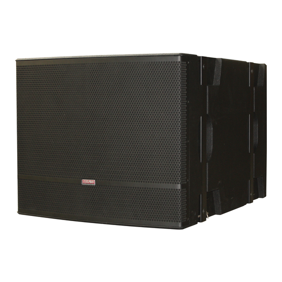
It has been architected to serve as a general purpose companion subwoofer for any high end EAW system or even for a competitive main system, but as the name suggests it is an obvious choice to use in conjunction with the NTL720. This professional, high output yet compact premium... -
Page 11: Amplification
There are two NTS250 models, differing only in the AC mains supply: NTS250 (115 V) Nominal AC mains: 100 V to 120 V, 50 Hz to 60 Hz NTS250 (230 V) Nominal AC mains: 220 V to 240 V, 50 Hz to 60 Hz... -
Page 12: Ac Mains Connection
6 . 2 AC M a i n s C o n n e c t i o n This section details the requirements for the AC mains connection required by each NTS250 loudspeaker. 6.2.1 AC MAINS SUPPLY WARNING: Read all instruction and cautionary notes concerning electrical power in the “EAW Loudspeaker Owner’s Manual”. -
Page 13: Ac Mains Cable
230 V NETZSPANNUNG AN, WENN DER LAUTSPRECHER FÜR 115 V KONFIGURIERT IST. SOFORTIGE, KATASTROPHALE SCHÄDENSIND DIE FOLGE. ES BESTEHT DIE GEFAHR VON FEUER, VERLETZUNG ODER TOD. Each NTS250 model Model 115 V 230 V manufactured for a particular nominal AC mains voltage, either... -
Page 14: Netzkabel
The NTS250 is compatible with these nominal AC mains: 100 V, 110 V, 115 V, 120 V, 220 V, 230 V, and 240 V at 50 Hz to 60 Hz. -
Page 15: Power Cord Receptacle
AC L O O P C o n n e c t o r The Neutrik Powercon AC mains and AC loop connectors are wired in parallel to provide an AC mains inlet and outlet on each NTS250. Neutrik NAC3FCB From ac Mains Out The blue AC mains inlet mates with a Neutrik Powercon NACFC3A (supplied). -
Page 16: Operating Temperature
6.10.1 ANALOG SIGNAL INPUT CONNECTION The two XLR-type input connectors on the rear of each NTS250, one female and one male, are designed for professional audio signal levels, nominally 0 dBu (= 0.775 V). Normally, use the female XLR as the signal input. Use the male XLR as a loop-thru output to connect the same signal input to additional NTS250s. -
Page 17: Network Configurations
Connect the USB port in the rear panel of the first NTS250 to a computer with the EAWPilot control program installed. Connect one of the U-Net ports on the rear panel of the first NTS250 to a U-Net port on the next NTS250. Continue daisy-chaining the remaining NTS250 U-Net ports until they are all connected. - Page 18 Connect one of the U-Net ports on the UX8800’s rear panel to a U-Net port on the NTS250. If there are more than one NTS250, connect the other U-Net port on the NTS250 to the next NTS250, and so on.
-
Page 19: Array Operation
HYPER-CARDIOD CARDIOD From this revolutionary fast set up optimized for the NTS250 the flexibility to perform pattern control from an array continues. Users can interface with the onboard processing of the NTS250 through EAW Pilot software and tailor the output pattern of multiple NTS250 subwoofers to match defined cancellation angles and a center frequency of cancellation. -
Page 20: Signal Processing
AC Loop connector. Connect no more than three NTS250s to the AC Loop connector of a single NTS250. If the circuit breaker should trip, the first NTS250 will continue to operate, but all the NTS250s connected via the AC Loop connector will stop working. Determine what caused the circuit breaker to trip and remedy the situation before resetting the circuit breaker. -
Page 21: Rigging & Handling
NTS250 levels. RIGGING & HANDLING NTS250 arrays may be suspended via M10 mounting points or the accessory FB152 Fly Bar, ground- stacked, or used as pole mount bases. This manual will cover subwoofer suspension using M10 mounting points and pole mounting applications. Suspension using the FB152 Fly Bar and ground- stacking applications are detailed in the FB152 Rigging &... -
Page 22: Rigging Warnings
WARNING: When four (4) M10 threaded Permanent Installation (PI) suspension points are used the array Working Load Limit (WLL), Total Vertical Pull, is limited to ten (10) NTS250 Subwoofers. In order to obtain full WLL, all four (4) M10 threaded Permanent Installation (PI) suspension points must be vertically attached to the support structure, and the array must be suspended vertically. - Page 23 8.3.5 POLE MOUNTING Up to two (2) NTS250 subwoofers may be used as a base for pole-mountable loudspeakers. In this configuration a 35 mm/1.38 in diameter loudspeaker pole is inserted between the NTS250s pole cup and the pole cup of the loudspeaker. The pole may be a fixed length or height adjustable. In either case it must be rated to support the weight of the pole mounted loudspeaker.
-
Page 24: Service, Inspection, And Maintenance
C o n t a c t i n g E AW We have tried to answer any questions you may have about the NTS250 in this manual and in the EAWPilot help files. Should you need further assistance, please do not hesitate to contact us. You can contact us in several different ways. -
Page 25: Block Diagram
1 0 . 1 S y s t e m F l o w D i a g r a m The block diagram shows the signal flow for two NTS250s. As can be seen, the audio input signal, AC mains, and the U-Net signal can be looped from one NTS250 to additional NTS250s. -
Page 26: Block Diagram
1 0 . 2 B l o c k d i a g r a m The block diagram shows the DSP blocks for the NTS250. The user DSP is configurable using the EAWPilot software application. The present DSP is not user-configurable and is designed to optimize the performance of the NTS250. - Page 27 This page left intentionally blank. Page...
- Page 28 One Main Street Whitinsville, MA, USA 01588 TEL 508-234-6158 FAX 508-234-6479 © 2010 LOUD Technologies Inc. All rights reserved. P/N RD0511 Rev A March 2010...
Need help?
Do you have a question about the NTS250 and is the answer not in the manual?
Questions and answers