Yamaha RX-V359 Owner's Manual
Hide thumbs
Also See for RX-V359:
- Service manual (74 pages) ,
- Owner's manual (74 pages) ,
- Owner's manual (74 pages)

Related Manuals for Yamaha RX-V359


Summary of Contents for Yamaha RX-V359
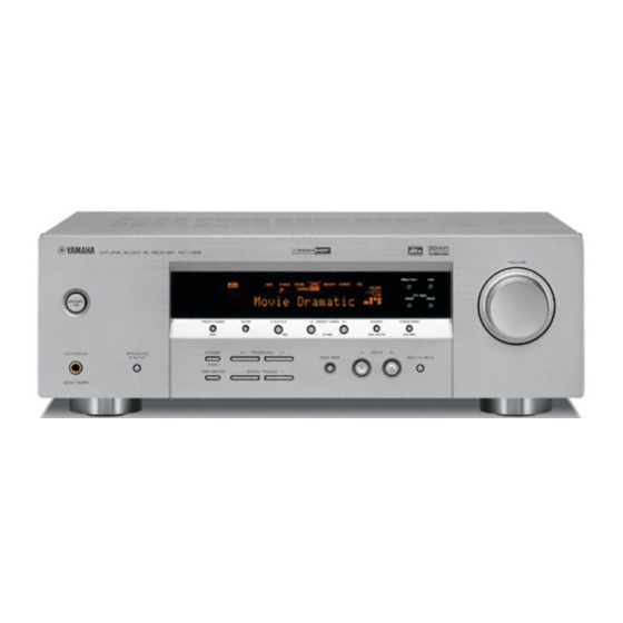
- Page 1 RX-V359 AV Receiver Ampli-tuner audio-vidéo OWNER’S MANUAL MODE D’EMPLOI BEDIENUNGSANLEITUNG BRUKSANVISNING MANUALE DI ISTRUZIONI MANUAL DE INSTRUCCIONES...
- Page 2 YAMAHA will not be proceed as follows: held responsible for any damage resulting from use The wire which is coloured BLUE must be connected of this unit with a voltage other than specified.
-
Page 3: Table Of Contents
CONTENTS INTRODUCTION ADVANCED OPERATION FEATURES............. 2 SET MENU ............44 GETTING STARTED..........3 Using SET MENU........... 45 SOUND MENU............45 Supplied accessories ..........3 INPUT MENU............47 Installing batteries in the remote control ....3 OPTION MENU............48 CONTROLS AND FUNCTIONS ......4 Front panel .............. -
Page 4: Features
6 additional input jacks for discrete multi-channel input Decoders and DSP circuits A SET MENU that allows you to optimize this unit to Proprietary YAMAHA technology for the creation of suit your individual audiovisual system multi-channel surround sound Component video input/output capability... -
Page 5: Getting Started
GETTING STARTED GETTING STARTED Supplied accessories Check that you received all of the following parts. Remote control Batteries (2) AM loop antenna (AA, R06, UM-3) DTV/CBL VCR POWER MD/CD-RV-AUX MULTI CH IN TUNER A/B/C/D/E PRESET STANDARD 5CH STEREO NIGHT SLEEP TEST STRAIGHT VOLUME... -
Page 6: Controls And Functions
CONTROLS AND FUNCTIONS CONTROLS AND FUNCTIONS Front panel 8 9 0 A B C VOLUME FREQ TEXT PTY SEEK MODE START STANDBY PRESET TUNING FM AM A B C D E PRESET TUNING MEMORY TUNING MODE EDIT NEXT SET MENU MAN'L AUTO FM AUTO MAN'L STRAIGHT... - Page 7 CONTROLS AND FUNCTIONS A EON K INPUT MODE Selects a radio program type (NEWS, AFFAIRS, INFO, Selects either digital or analog input signals exclusively or or SPORT) for automatic tuning. sets this unit to automatically detect the type of input signals and select the corresponding input signals when B PTY SEEK START one component is connected via both digital and analog...
-
Page 8: Remote Control
CONTROLS AND FUNCTIONS Remote control 1 Infrared signal transmitter Outputs infrared control signals. Aim the transmitter at the component you want to operate. 2 Input selector buttons DTV/CBL VCR POWER Select the input source. MD/CD-RV-AUX MULTI CH IN 3 A/B/C/D/E Selects one of the 5 preset station groups (A to E) when TUNER A/B/C/D/E... - Page 9 CONTROLS AND FUNCTIONS F STRAIGHT Using the remote control Turns the sound field programs off or on. When this unit is The remote control transmits a directional infrared ray. in the “STRAIGHT” mode, 2-channel or multi-channel Be sure to aim the remote control directly at the remote control sensor on this unit during operation.
-
Page 10: Front Panel Display
CONTROLS AND FUNCTIONS Front panel display V-AUX DTV/CBL MD/CD-R TUNER VIRTUAL SILENT CINEMA AUTO TUNED STEREO MEMORY MUTE VOLUME STANDARD NIGHT HiFi DSP PTY HOLD PS PTY RT CT EON SLEEP DIGITAL L C R LFE SL 1 Decoder indicators E CINEMA DSP indicator The respective indicator lights up when any of the Lights up when you select a CINEMA DSP program. -
Page 11: Rear Panel
CONTROLS AND FUNCTIONS Rear panel AUDIO MULTI CH INPUT VIDEO COMPONENT VIDEO TUNER FRONT DTV/ DTV/ SURROUND DIGITAL CENTER INPUT SPEAKERS WOOFER V-AUX COAXIAL FRONT OPTICAL MONITOR OUT DTV/CBL FRONT CENTER SURROUND (PLAY) CD-R (REC) WOOFER MONITOR AUDIO OUTPUT 1 MULTI CH INPUT jacks See page 16 for connection information. -
Page 12: Connections
60˚ 80˚ Subwoofer (SW) The use of a subwoofer, such as the YAMAHA Active Servo Processing Subwoofer System, is effective not only for reinforcing bass frequencies from any or all channels, but also for high fidelity reproduction of the LFE (low- frequency effect) channel included in Dolby Digital and DTS software. -
Page 13: Connecting Speakers
CONNECTIONS Connecting to the FRONT A SPEAKERS Connecting speakers terminals Be sure to connect the left channel (L), right channel (R), “+” (red) and “–” (black) properly. If the connections are faulty, no sound will be heard from the speakers, and if the polarity of the speaker connections is incorrect, the sound Red: positive (+) Black: negative (–) - Page 14 Connect a center speaker (3) to these terminals. SURROUND terminals Connect surround speakers (4, 5) to these terminals. SUBWOOFER OUTPUT jack Connect a subwoofer with built-in amplifier (6) (such as the YAMAHA Active Servo Processing Subwoofer System) to this jack. Speaker layout...
-
Page 15: Information On Jacks And Cable Plugs
CONNECTIONS Information on jacks and cable plugs Audio jacks and cable plugs Video jacks and cable plugs COMPONENT VIDEO AUDIO DIGITAL AUDIO DIGITAL AUDIO VIDEO COAXIAL OPTICAL (White) (Red) (Orange) (Yellow) (Green) (Blue) (Red) Left and right Coaxial Optical Composite Component analog audio digital audio... -
Page 16: Connecting Video Components
CONNECTIONS Connecting a DVD recorder/VCR Connecting video components Connect the audio signal input jacks of your video component to the VCR AUDIO OUT jacks of this unit. Connecting a video monitor Then connect the video signal input jack of the video Connect the video input jack of your video monitor to the component to the VCR VIDEO OUT jack of this unit for MONITOR OUT jack. - Page 17 CONNECTIONS Cable TV or Satellite tuner Audio out Video Audio AUDIO MULTI CH INPUT VIDEO COMPONEN FRONT DTV/ DTV/ SURROUND DIGITAL CENTER INPUT WOOFER V-AUX COAXIAL OPTICAL MONITOR OUT DTV/CBL SURR (PLAY) CD-R (REC) WOOFER MONITOR AUDIO OUTPUT Audio out Audio in Video in Video out...
- Page 18 CONNECTIONS Connecting to the COMPONENT VIDEO jacks You can enjoy high-quality pictures by connecting your video monitor and video source components to this unit using COMPONENT VIDEO connections. Note Be sure to connect your video source components in the same way you connect your video monitor to this unit. For example, if you connect your video monitor to this unit using a COMPONENT VIDEO connection, connect your video source components to this unit using the COMPONENT VIDEO connection.
-
Page 19: Connecting Audio Components
CONNECTIONS Connecting a CD recorder/MD recorder Connecting audio components Connect the input jacks of your CD recorder or MD recorder to the MD/CD-R OUT (REC) jacks. Connecting a CD player Connect the output jacks of your CD recorder or MD Connect the output jacks of your CD player to the CD recorder to the MD/CD-R IN (PLAY) jacks to play a jacks of this unit. -
Page 20: Connecting The Fm And Am Antennas
If you experience poor reception quality, install an outdoor antenna. Consult the nearest authorized YAMAHA dealer or service center about outdoor antennas. • The AM loop antenna should always be connected, even if an outdoor AM antenna is connected to this unit. -
Page 21: Connecting The Power Cable
CONNECTIONS Connecting the power cable Turning on the power Once all connections are complete, plug the power cable When all connections are complete, turn on this unit. into the AC wall outlet. STANDBY/ON Power cable VOLUME FREQ TEXT PTY SEEK MODE START STANDBY... -
Page 22: Setup
SETUP SETUP The “BASIC MENU” feature is a useful way to set up your system quickly and with minimal effort. Press + to enter “1 SETUP”. • If you wish to configure this unit manually using more precise adjustments, use the detailed parameters in “SOUND MENU” (see page 45). - Page 23 SETUP Press d to confirm your selection and then Press d to confirm your selection. press +/– to select the number of speakers connected to this unit. If you selected “SET” in the previous step, you will hear a test tone from each speaker in turn. “CHECK:TestTone”...
- Page 24 SETUP Press +/– to adjust the balance between the front left and right speakers. Press d / u to select a speaker and then +/– to adjust the balance. Press + to increase the value. Press – to decrease the value. •...
-
Page 25: Playback
PLAYBACK PLAYBACK CAUTION Extreme caution should be exercised when you play back CDs encoded in DTS. If you play back a CD encoded in DTS on a DTS-incompatible CD player, you will only hear some unwanted noise that may damage your speakers. Check whether your CD player supports CDs encoded in DTS. Also, check the sound output level of your CD player before you play back a CD encoded in DTS. - Page 26 PLAYBACK Press PROGRAM l / h on the front panel Rotate VOLUME on the front panel (or press VOLUME +/– on the remote control) to adjust (or press PROG +/– on the remote control) the volume to the desired output level. repeatedly to select the desired sound field program.
-
Page 27: Additional Operations
PLAYBACK Selecting the MULTI CH INPUT Additional operations component as the input source Use this feature to select the component connected to the Listening with headphones using MULTI CH INPUT jacks (see page 16) as the input SILENT CINEMA source. SILENT CINEMA allows you to enjoy multi-channel Press MULTI CH INPUT on the front panel (or music or movie sound, including Dolby Digital and DTS... - Page 28 PLAYBACK Selecting the input modes Adjusting speaker levels during This unit comes with a variety of input jacks. Do the playback following to select the type of input signals you want to You can adjust the output level of each speaker while use.
- Page 29 PLAYBACK Using the test tone Notes Use the test tone to set speaker levels so that the volume from each speaker is identical when heard from your • You cannot use the test tone if headphones are connected to the listening position.
- Page 30 PLAYBACK Displaying information about the input FORMAT Signal format display. When this unit cannot detect a source digital signal, it automatically switches to analog You can display the format, sampling frequency, channel input. and bit rate of the current input signal. Display status: Analog, Digital, Dolby Digital, DTS, PCM, Press one of the input selector buttons on...
- Page 31 PLAYBACK Using the sleep timer Playing video sources in the background Use this feature to automatically set this unit to the standby mode after a certain amount of time. The sleep You can combine a video image from a video source with timer is useful when you are going to sleep while this unit sound from an audio source.
-
Page 32: Sound Field Programs
This unit is equipped with a variety of precise digital decoders that allow you to enjoy multi-channel playback from almost any stereo or multi-channel sound source. This unit is also equipped with a YAMAHA digital sound field processing (DSP) chip containing several sound field programs which you can use to enhance your playback experience. -
Page 33: Sound Field Program Descriptions
SOUND FIELD PROGRAMS Sound field program descriptions Program Program Features category 2CH STEREO Downmixes multi-channel sources to 2 channel or plays back 2-channel sources as they are. 2CH STEREO Concert Hall HiFi DSP processing. This program produces the excitement of a live concert hall. The Roxy Thtr MUSIC HiFi DSP processing. - Page 34 SOUND FIELD PROGRAMS Enjoying 2-channel sources using the Editing sound fields parameters standard decoders You can enjoy good quality sound with the factory preset parameters. Although you do not have to change the initial Signals input from 2-channel sources can also be played settings, you can change some of the parameters to better back on multi-channels.
- Page 35 SOUND FIELD PROGRAMS For 2CH STEREO: Using Virtual CINEMA DSP Virtual CINEMA DSP allows you to enjoy the CINEMA Direct DIRECT DSP programs without surround speakers by creating Function: 2-channel stereo direct. Bypasses the virtual speakers. decoders and DSP processors of this unit If you set “SURR”...
-
Page 36: Recording
RECORDING RECORDING Recording adjustments and other operations are performed from the recording components. Refer to the operating instructions for those components. Notes • When this unit is set to the standby mode, you cannot record between other components connected to this unit. •... -
Page 37: Fm/Am Tuning
FM/AM TUNING FM/AM TUNING There are 2 tuning methods: automatic and manual. Automatic tuning is effective when station signals are strong and there is no interference. If the signal from the station you want to select is weak, tune into it manually. You can also use the automatic and manual preset tuning features to store up to 40 stations (A1 to E8: 8 preset station numbers in each of the 5 preset station groups). -
Page 38: Manual Tuning
FM/AM TUNING Manual tuning Press TUNING MODE so that the AUTO indicator disappears from the front panel If the signal received from the station you want to select is display. weak, tune into it manually. TUNING MODE Note AUTO MAN'L Manually tuning into an FM station automatically switches the tuner to monaural reception to increase the signal quality. -
Page 39: Automatic Preset Tuning
FM/AM TUNING Automatic preset tuning Press and hold MEMORY for more than 3 seconds. You can use the automatic preset tuning feature to store The preset station number as well as the MEMORY FM stations with strong signals up to 40 (A1 to E8: 8 and AUTO indicators flashes. -
Page 40: Manual Preset Tuning
FM/AM TUNING Manual preset tuning Press PRESET/TUNING l / h to select a preset station number (1 to 8) while the You can also store up to 40 stations (A1 to E8: 8 preset MEMORY indicator is flashing. station numbers in each of the 5 preset station groups) •... -
Page 41: Selecting Preset Stations
FM/AM TUNING Selecting preset stations Press PRESET/TUNING l / h on the front panel (or PRESET +/– on the remote control) You can tune into any desired station simply by selecting to select the desired preset station number (1 the preset station group and number under which it was to 8). -
Page 42: Exchanging Preset Stations
FM/AM TUNING Exchanging preset stations Select preset station “A5” using A/B/C/D/E and PRESET/TUNING l / h. You can exchange the assignments of two preset stations “A5” and the MEMORY indicator flash in the front with each other. The example below describes the panel display. -
Page 43: Radio Data System Tuning
RADIO DATA SYSTEM TUNING RADIO DATA SYSTEM TUNING Radio Data System (U.K. and Europe models only) is a data transmission system used by FM stations in many countries. The Radio Data System function is carried out among the network stations. This unit can receive various Radio Data System data such as PS (program service), PTY (program type), RT (radio text), CT (clock time), and EON (enhanced other networks) when receiving Radio Data System broadcasting stations. -
Page 44: Using The Radio Data System Station Network
RADIO DATA SYSTEM TUNING Using the Radio Data System Press PTY SEEK START to start searching station network for all the available Radio Data System preset stations. Use this feature to receive the EON (enhanced other The name of the selected program type flashes and networks) data service of the Radio Data System station the PTY HOLD indicator lights up in the front panel network. -
Page 45: Displaying The Radio Data System Information
RADIO DATA SYSTEM TUNING Displaying the Radio Data System VOLUME information FREQ TEXT PTY SEEK MODE START STANDBY PRESET TUNING FM AM A B C D E PRESET TUNING MEMORY TUNING MODE Use this feature to display the 4 types of the Radio Data EDIT NEXT SET MENU... -
Page 46: Set Menu
SET MENU SET MENU You can use the following parameters in “SET MENU” to adjust a variety of system settings and customize the way this unit operates. Change the initial settings (indicated in bold under each parameter) to reflect the needs of your listening environment. -
Page 47: Using Set Menu
SET MENU Using SET MENU SOUND MENU Use the remote control to access and adjust each Use this menu to manually adjust any speaker settings. parameter. Notes TEST STRAIGHT • If you select “SETUP” (see page 20) and then select “SET” VOLUME PROG PROG... - Page 48 SET MENU Surround left/right speakers 1C SURR Speaker distance 2 SP DISTANCE Choices: LRG (large), SML (small), NON (none) Use this feature to manually adjust the distance of each speaker and the delay applied to the respective channel. • Select “LRG” if you have large surround left and right Ideally, each speaker should be the same distance from the speakers.
-
Page 49: Input Menu
SET MENU Dynamic range 4 D.RANGE INPUT MENU Use this feature to select the amount of dynamic range compression to be applied to your speakers or Use this menu to reassign input jacks or select the input headphones. This setting is effective only when the unit is mode. -
Page 50: Option Menu
SET MENU OPTION MENU Use this menu to adjust the optional system parameters. Display settings 1 DISPLAY SET Dimmer DIMMER Use this feature to adjust the brightness of the front panel display. Choices: – 4 to 0 Control step: 1 •... -
Page 51: Troubleshooting
Refer to the table below when this unit does not function properly. If the problem you are experiencing is not listed below or if the instruction below does not help, turn off this unit, disconnect the power cable, and contact the nearest authorized YAMAHA dealer or service center. General... - Page 52 TROUBLESHOOTING Problem Cause Remedy page The sound suddenly The protection circuitry has been activated Check that the speaker wires are not touching each — goes off. because of a short circuit, etc. other and then turn this unit back on. The sleep timer has turned off this unit.
- Page 53 TROUBLESHOOTING Problem Cause Remedy page Dolby Digital or DTS The connected component is not set to Make an appropriate setting following the operating — sources cannot be output Dolby Digital or DTS digital instructions for your component. played. (Dolby Digital signals.
- Page 54 TROUBLESHOOTING Tuner Problem Cause Remedy page FM stereo reception is The characteristics of FM stereo Check the antenna connections. noisy. broadcasts may cause this problem Try using a high-quality directional FM — when the transmitter is too far away or antenna.
-
Page 55: Resetting The System
RESETTING THE SYSTEM RESETTING THE SYSTEM Use this feature to reset all the parameters of this unit to the initial factory settings. Notes • This procedure completely resets all the parameters of this unit including the “SET MENU” parameters. • The initial factory settings are activated next time you turn on this unit. To cancel the initialization procedure at any time without making any changes, press STRAIGHT repeatedly to select “CANCEL”... -
Page 56: Glossary
GLOSSARY GLOSSARY DTS (Digital Theater Systems) Audio information Digital Surround DTS digital surround was developed to replace the analog Dolby Digital soundtracks of movies with a 5.1-channel digital sound Dolby Digital is a digital surround sound system that gives track, and is now rapidly gaining popularity in movie you completely independent multi-channel audio. -
Page 57: Sound Field Program Information
SILENT CINEMA color, brightness and synchronization data. A composite YAMAHA has developed a natural, realistic sound effect video jack on a video component transmits these three DSP algorithm for headphones. Parameters for elements combined. -
Page 58: Specifications
SPECIFICATIONS SPECIFICATIONS AUDIO SECTION FM SECTION • Minimum RMS Output Power for Front, Center, Surround • Tuning Range [U.S.A. and Canada models] [U.S.A. and Canada models] ......87.5 to 107.9 MHz 1 kHz, 0.9% THD, 8 /6 ..........110 W [Other models] ..........
Need help?
Do you have a question about the RX-V359 and is the answer not in the manual?
Questions and answers