Table of Contents
Advertisement
Advertisement
Table of Contents
Troubleshooting

Related Manuals for Yamaha Virago XV125S


Summary of Contents for Yamaha Virago XV125S
- Page 1 OWNER’S MANUAL XV125S 5AJ-28199-E3...
- Page 3 EAU00001 Welcome to the Yamaha world of motorcycling! As the owner of a XV125S, you are benefiting from Yamaha’s vast experience in and newest technology for the design and the manufacture of high-quality products, which have earned Yamaha a reputation for dependability.
-
Page 4: Important Manual Information
If there is any question concerning this manual, please consult your Yamaha dealer. - Page 5 IMPORTANT MANUAL INFORMATION EW000002 PLEASE READ THIS MANUAL CAREFULLY AND COMPLETELY BEFORE OPERATING THIS MOTORCYCLE.
- Page 6 EAU00008 XV125S OWNER’S MANUAL ©1999 by Yamaha Motor Co., Ltd. 1st Edition, June 1999 All rights reserved. Any reprinting or unauthorized use without the written permission of Yamaha Motor Co., Ltd. is expressly prohibited. Printed in Japan.
-
Page 7: Table Of Contents
EAU00009 TABLE OF CONTENTS GIVE SAFETY THE RIGHT OF WAY ....1-1 Sidestand/clutch switch operation check..3-11 DESCRIPTION .............2-1 PRE-OPERATION CHECKS.........4-1 Left view............2-1 Pre-operation check list ........4-1 Right view ............2-2 Controls/Instruments ........2-3 OPERATION AND IMPORTANT RIDING POINTS..............5-1 INSTRUMENT AND CONTROL Starting the engine ..........5-1 FUNCTIONS............3-1 Starting a warm engine ........5-3 Main switch ............3-1... - Page 8 TABLE OF CONTENTS Carburetor adjustment ........6-15 Battery.............6-30 Idle speed adjustment ........6-15 Fuse replacement...........6-32 Throttle cable free play adjustment....6-16 Headlight bulb replacement......6-33 Valve clearance adjustment ......6-16 Turn signal light bulb replacement ....6-34 Tires..............6-17 Taillight bulb replacement ......6-35 Wheels ............6-19 Supporting the motorcycle ......6-36 Clutch lever free play adjustment....6-19 Front wheel removal........6-36 Front brake lever free play adjustment ..6-20...
-
Page 10: Give Safety The Right Of Way
EAU00021 Q GIVE SAFETY THE RIGHT OF WAY Motorcycles are fascinating vehicles, which can give you an unsurpassed feeling of power and freedom. However, they also impose certain limits, which you must accept; even the best motorcycle does not ignore the laws of physics. Regular care and maintenance are essential for preserving your motorcycle’s value and operat- ing condition. -
Page 12: Description
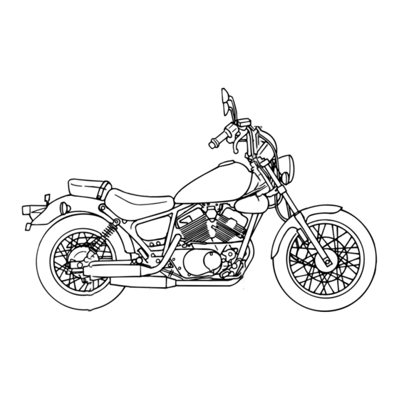
EAU00026 DESCRIPTION Left view 1. Headlight (page 6-33) 6. Helmet holder (page 3-9) 2. Steering lock (page 3-8) 7. Rear shock absorber spring preload 3. Fuel cock (page 3-7) adjusting ring (page 3-10) 4. Main switch (page 3-1) 8. Shift pedal (page 3-4) 5. -
Page 13: Right View
DESCRIPTION Right view 9. Battery (page 6-30) 14. Rear shock absorber spring preload 10. Air filter (page 6-12) adjusting ring (page 3-10) 11. Rear brake pedal (page 3-5, 6-21) 12. Oil filter (page 6-9) 13. Tool kit (page 6-1) -
Page 14: Controls/Instruments
DESCRIPTION Controls/Instruments 15 16 15. Clutch lever (page 3-4, 6-19) 20. Throttle grip (page 6-16) 16. Left handlebar switches (page 3-2) 21. Fuel tank cap (page 3-5) 17. Speedometer (page 3-2) 18. Right handlebar switches (page 3-3) 19. Front brake lever (page 3-4, 6-20) -
Page 15: Instrument And Control Functions
EAU00027 INSTRUMENT AND CONTROL FUNCTIONS EAU00054 P (Parking) The taillight and auxiliary light come on but all other circuits are off. With the key at “OFF”, push it into the main switch, turn it coun- terclockwise to “P”, and remove it. To cancel the parking, turn the key clockwise. -
Page 16: Speedometer
INSTRUMENT AND CONTROL FUNCTIONS NOTE: (for German model equipped with speed limiter only) This motorcycle is equipped with a speed limiter which prevents it from exceeding a top speed of 80 km/h. 1. Odometer 1. Pass switch “&” 2. Trip odometer 2. - Page 17 INSTRUMENT AND CONTROL FUNCTIONS EAU00127 EAU00138 Turn signal switch Engine stop switch To signal a right-hand turn, push The engine stop switch is a safety the switch to “6”. To signal a left- device for use in an emergency hand turn, push the switch to such as when the motorcycle over- “4”.
-
Page 18: Clutch Lever
INSTRUMENT AND CONTROL FUNCTIONS N. Neutral 1. Shift pedal EAU00152 EAU00158 Clutch lever Front brake lever EAU00157 Shift pedal The clutch lever is located on the The front brake lever is located on This motorcycle is equipped with a left handlebar, and the ignition cir- the right handlebar. -
Page 19: Rear Brake Pedal
INSTRUMENT AND CONTROL FUNCTIONS NOTE: This tank cap cannot be closed unless the key is in the lock. The key cannot be removed if the cap is not locked properly. EW000023 sure properly 1. Open installed locked place EAU00162 EAU00167 Rear brake pedal Fuel tank cap before riding the motorcycle. -
Page 20: Fuel
INSTRUMENT AND CONTROL FUNCTIONS EAU00185 EAU00191 Recommended fuel: Always wipe off spilled fuel imme- Regular unleaded gasoline diately with a dry and clean soft with a research octane cloth. Fuel may deteriorate painted number of 91 or higher. surfaces or plastic parts. Fuel tank capacity: Total: 9.5 L... -
Page 21: Fuel Cock
INSTRUMENT AND CONTROL FUNCTIONS NOTE: The fuel cock operates on vacuum from the engine when set at “ON” or “RES”. If the line connecting the cock to the carburetor intake mani- fold is not connected or has a leak, the cock will not function properly. 1. -
Page 22: Starter (Choke) "1
INSTRUMENT AND CONTROL FUNCTIONS 1. Arrow mark pointing to “PRI” 1. Starter (choke) “1” 1. Steering lock EAU02976 EAU02934 Starter (choke) “1” Steering lock This indicates prime. With the lever To lock the steering Starting a cold engine requires a in this position, fuel flows whether Turn the handlebars all the way to richer air-fuel mixture. -
Page 23: Seat
INSTRUMENT AND CONTROL FUNCTIONS 1. Bolt ( 1. Projection 1. Helmet holder 2. Seat holder 2. Open EAU03020 Seat EAU00260 To install Helmet holder To remove 1. Insert the projection on the To open the helmet holder, insert 1. Remove panels A and B. (See front of the rider seat into the the key in the lock and turn it as page 6-6 for panel removal... -
Page 24: Rear Shock Absorber Adjustment
INSTRUMENT AND CONTROL FUNCTIONS EAU00330 Stan- Soft Hard Sidestand dard Adjusting This model is equipped with an position ignition circuit cut-off system. The EW000040 motorcycle must not be ridden when the sidestand is down. The Always adjust each shock sidestand is located on the left side absorber to the same setting. -
Page 25: Sidestand/Clutch Switch Operation Check
PULL IN CLUTCH LEVER AND of a malfunction, return the motor- PUSH THE START SWITCH. cycle to a Yamaha dealer immedi- ately for repair. ENGINE WILL START. CLUTCH SWITCH IS OK. 3-11... -
Page 26: Pre-Operation Checks
EAU01114 PRE-OPERATION CHECKS Owners are personally responsible for their vehicle’s condition. Your motorcycle’s vital functions can start to deteriorate quickly and unexpectedly, even if it remains unused (for instance, if it is exposed to the elements). Any damage, fluid leak or loss of tire pressure could have serious consequences. Therefore, it is very important that, in addition to a thorough visual inspection, you check the following points before each ride. - Page 27 PRE-OPERATION CHECKS ITEM CHECKS PAGE 9 Check for smooth operation. Sidestand pivot 6-28 9 Lubricate if necessary. 9 Make sure that all nuts, bolts, and screws are properly tightened. Chassis fasteners — 9 Tighten if necessary. 9 Check fuel level. Fuel tank 3-5 ~ 3-6 9 Fill with fuel if necessary.
-
Page 28: Operation And Important Riding Points
Consult The engine can be started only Yamaha dealer regarding any under one of the following condi- control or function that you do tions: not thoroughly understand. 8 The transmission is in neutral. - Page 29 OPERATION AND IMPORTANT RIDING POINTS TURN THE MAIN SWITCH TO “ON” AND THE ENGINE STOP SWITCH TO “#”. IF THE TRANSMISSION IS IN NEUTRAL IF THE TRANSMISSION IS IN GEAR AND THE SIDESTAND IS DOWN, AND THE SIDESTAND IS UP, PULL IN THE CLUTCH LEVER AND PUSH START SWITCH.
-
Page 30: Starting A Warm Engine
(choke) should be on. If the light does not completely. come on, ask a Yamaha dealer to inspect it. NOTE: The engine is warm when it 4. Turn on the starter (choke) and... -
Page 31: Shifting
OPERATION AND IMPORTANT RIDING POINTS EC000048 EAU02941 Recommended shift points (for Switzerland only) 8 Do not coast for long periods The recommended shift points are with the engine off, and do shown in the table below. not tow the motorcycle a long distance. -
Page 32: Tips For Reducing Fuel Consumption
OPERATION AND IMPORTANT RIDING POINTS EAU00424 EAU00436 EAU00443 Tips for reducing fuel Engine break-in 0 ~ 150 km consumption There is never a more important Avoid operation above 1/3 throttle. Your motorcycle’s fuel consump- period in the life of your motorcy- Stop the engine and let it cool for 5 tion depends to a large extent on cle than the period between zero... -
Page 33: Parking
If any engine trouble should occur The exhaust system is hot. Park during the break-in period, consult the motorcycle in a place where a Yamaha dealer immediately. pedestrians or children are not likely to touch the motorcycle. Do not park the motorcycle on a slope or soft ground;... -
Page 34: Periodic Maintenance And Minor Repair
If you are not familiar with motor- motorcycle in the safest and most cycle service, this work should be efficient condition possible. Safety done by a Yamaha dealer. is an obligation of the motorcycle owner. The maintenance and lubri- cation schedule chart should be... - Page 35 Yamaha dealer for service. EW000063 Modifications to this motorcycle not approved by Yamaha may cause loss of performance, and render it unsafe for use. Consult a Yamaha dealer before attempting any changes.
-
Page 36: Periodic Maintenance And Lubrication
PERIODIC MAINTENANCE AND MINOR REPAIR EAU00473 PERIODIC MAINTENANCE AND LUBRICATION Every Every 6,000 km 12,000 km INITIAL ITEM CHECKS AND MAINTENANCE JOBS 1,000 km 6 months 12 months (Whichever (Whichever comes first) comes first) 9 Check fuel hoses and vacuum hose for cracks or damage. 1 * Fuel line 9 Replace if necessary. - Page 37 PERIODIC MAINTENANCE AND MINOR REPAIR Every Every 6,000 km 12,000 km INITIAL ITEM CHECKS AND MAINTENANCE JOBS 1,000 km 6 months 12 months (Whichever (Whichever comes first) comes first) 9 Check bearing for looseness or damage. 11 * Wheel bearings 9 Replace if necessary.
- Page 38 Engine oil 9 Change. (Warm engine before draining.) Engine oil filter element 9 Replace. Since these items require special tools, data and technical skills, they should be serviced by a Yamaha dealer. EAU02970 NOTE: 8 The air filter needs more frequent service if you are riding in unusually wet or dusty areas.
-
Page 39: Panel Removal And Installation
PERIODIC MAINTENANCE AND MINOR REPAIR 1. Panel A 1. Panel B EAU01122 EAU01156 Panel removal and Panel A installation To remove The panels illustrated need to be Pull outward on the rear of the removed to perform some of the panel, then slide it forward to maintenance described... -
Page 40: Panel B
PERIODIC MAINTENANCE AND MINOR REPAIR 1. Holder ( 2) 1. Holder ( 2) 2. Bracket ( 2) 2. Grommet EAU01156 3. Grommet 3. Projection Panel B 4. Projection 4. Bracket ( 2) To remove To install To install Pull outward on the rear of the Hook the front of the panel on the Hook the front of the panel on the panel, then slide it forward to... -
Page 41: Spark Plugs
1. Remove the spark plug caps. the engine. Do not attempt to diagnose such problems yourself. Instead, take the motorcycle to a Yamaha dealer. You should periodically remove inspect the spark plugs because heat and deposits will cause any spark plug to slowly break down and erode. -
Page 42: Engine Oil
PERIODIC MAINTENANCE AND MINOR REPAIR NOTE: If a torque wrench is not available when you are installing a spark plug, a good estimate of the cor- rect torque is 1/4 to 1/2 turn past finger tight. Have the spark plug tightened to the specified torque as soon as possible. - Page 43 PERIODIC MAINTENANCE AND MINOR REPAIR 2. With engine stopped, check the oil level through the level window located at the lower part of the right side crankcase cover. NOTE: Wait a few minutes until the oil level settles before checking. 1.
- Page 44 PERIODIC MAINTENANCE AND MINOR REPAIR 7. Install the new oil filter, new O- ring and the oil filter cover. Tighten the oil filter cover bolts to the specified torque. Tightening torque: Oil filter cover bolt: 10 Nm (1.0 m·kg) 1. Oil filter cover bolt ( 3) 1.
- Page 45 PERIODIC MAINTENANCE AND MINOR REPAIR 9. Start the engine and warm up Recommended oil: minutes. While See page 8-1. warming up, check for oil leak- Oil quantity: age. If oil leakage is found, Total amount: stop the engine immediately 1.7 L and check for the cause.
- Page 46 PERIODIC MAINTENANCE AND MINOR REPAIR 1. Bolt ( 2) 1. Hose ( 2) 1. Screw ( 2) 1. Remove the bolts and the air 2. Remove the hoses from the air 3. Remove the screws and the air filter case. filter case.
-
Page 47: Air Filter
PERIODIC MAINTENANCE AND MINOR REPAIR 7. Pull element over frame, install the air filter in the case and tighten the wing nut. 8. Install the air filter cover. 9. Connect the hoses and install the air filter case. EC000082 1. Wing nut 1. -
Page 48: Carburetor Adjustment
A diagnostic tachometer must be cated adjustment. Most adjust- used for this procedure. ments should be left to a Yamaha dealer who has the professional 1. Attach the tachometer. Start knowledge and experience to do the engine and warm it up for so. -
Page 49: Throttle Cable Free Play Adjustment
This adjustment however, free play. should be left to a professional 3. Tighten the locknut. Yamaha service technician. 1. Adjusting nut 2. Locknut c. Free play EAU00634 Throttle cable free play... -
Page 50: Tires
PERIODIC MAINTENANCE AND MINOR REPAIR EAU00647 EW000083 Maximum load* 183 kg Tires Cold tire pressure Front Rear To ensure maximum performance, Proper loading of your motorcycle 175 kPa 200 kPa long service, and safe operation, Up to 90 kg (1.75 kg/cm , (2.0 kg/cm is important for several character- 1.75 bar) - Page 51 CHENG SHIN 130/90-15M/C 66P C-915 Have excessively worn tires Minimum tire tread replaced by a Yamaha dealer 1.6 mm depth (front and rear) immediately. Brakes, tires, and 1. Side wall related wheel parts replace- a.
-
Page 52: Wheels
If any 1. Locknut abnormal condition exists in a 2. Adjusting bolt c. Free play wheel, consult a Yamaha deal- EAU00694 er. Do not attempt even small Clutch lever free play repairs to the wheel. If a wheel... -
Page 53: Front Brake Lever Free Play Adjustment
2 ~ 5 mm. trol and an accident. Have a 6. Loosen the locknut at the 1. Loosen the locknut. Yamaha dealer inspect and crankcase side. 2. Turn the adjusting bolt in bleed the system if necessary. -
Page 54: Rear Brake Pedal Height And Free Play Adjustment
3. Tighten the locknut. It is advisable to have a Yamaha in direction b to decrease free dealer make this adjustment. play. EW000108... -
Page 55: Brake Light Switch Adjustment
Inspect the groove. If the turning the adjusting nut. groove has almost disappeared, Turn the adjusting nut in direction ask a Yamaha dealer to replace the a to make the brake light come on pads. earlier. Turn the adjusting nut in direction b to make the brake light come on later. -
Page 56: Inspecting The Brake Fluid Level
If the indicator reaches the wear brake fluid. Mixing fluids may causing the brakes to become inef- limit line, ask a Yamaha dealer to result in a harmful chemical fective. replace the shoes. reaction and lead to poor Before riding, check that the brake brake performance. -
Page 57: Brake Fluid Replacement
Always clean up spilled only by trained Yamaha service fluid immediately. personnel. Have the Yamaha deal- 8 Have a Yamaha dealer check er replace the following compo- the cause if the brake fluid nents during periodic maintenance level goes down. -
Page 58: Drive Chain Slack Adjustment
PERIODIC MAINTENANCE AND MINOR REPAIR To tighten the chain, turn the chain adjusting nuts in direc- tion a. To loosen the chain, turn the chain adjusting nuts in direction b and push the wheel forward. Turn each chain adjusting nut exactly the same amount to maintain cor- rect axle alignment. -
Page 59: Drive Chain Lubrication
PERIODIC MAINTENANCE AND MINOR REPAIR EAU00769 7. Adjust the free play in the Drive chain lubrication brake pedal. The chain consists of many parts EW000103 which work with each other. If the chain is not maintained properly, it Check the operation of the brake will wear out quickly. -
Page 60: Cable Inspection And Lubrication
Replace damaged cables as soon as possible to prevent unsafe conditions. Lubricate the cables and cable ends. If a cable does not operate smooth- ly, ask a Yamaha dealer to replace it. Recommended lubricant: Engine oil 6-27... -
Page 61: Brake And Shift Pedal Lubrication
Lubricate the pivoting parts. point and metal-to-metal contact surfaces. Check that the sidestand Recommended lubricant: Recommended lubricant: moves up and down smoothly. Engine oil Engine oil Recommended lubricant: Engine oil EW000113 If the sidestand does not move smoothly, consult a Yamaha deal- 6-28... -
Page 62: Front Fork Inspection
If any smoothly. free play can be felt, ask a Yamaha EC000098 dealer to inspect and adjust the steering. Inspection is easier if the If any damage or unsmooth move- front wheel is removed. -
Page 63: Wheel Bearings
If there is play in the front or rear Securely support the motorcycle wheel hub or if the wheel does not so there is no danger of it falling turn smoothly, have a Yamaha over. dealer inspect the wheel bearings. 1. Battery 2. - Page 64 PERIODIC MAINTENANCE AND MINOR REPAIR EC000099 EW000116 When inspecting the battery, be Battery electrolyte is poisonous UPPER LEVEL sure the breather hose is routed and dangerous, causing severe LOWER LEVEL correctly. If the breather hose is burns, etc. It contains sulfuric acid. positioned in such a way as to Avoid contact with skin, eyes or cause battery electrolyte or gas to...
-
Page 65: Fuse Replacement
Turn on the cycle. Make sure the breather switches and see if the electrical hose is properly connected device operates. If the fuse imme- damaged diately blows again, consult a obstructed. Yamaha dealer. 6-32... -
Page 66: Headlight Bulb Replacement
PERIODIC MAINTENANCE AND MINOR REPAIR EC000103 Do not use fuses of higher amper- age rating than those recommend- ed. Substitution of a fuse of improper rating can cause exten- sive electrical system damage and possibly a fire. 1. Screw ( 2) 1. -
Page 67: Turn Signal Light Bulb Replacement
5. Install the bulb cover, connec- 4. Put a new bulb into position tors and headlight unit. and secure it in place with the Ask a Yamaha dealer to adjust bulb holder. the headlight beam if neces- sary. 6-34... -
Page 68: Taillight Bulb Replacement
PERIODIC MAINTENANCE AND MINOR REPAIR 1. Bulb 1. Screw ( 2) 1. Bulb EAU01623 2. Remove the defective bulb by 2. Remove the defective bulb by Taillight bulb replacement pushing it inward and turning pushing it inward and turning 1. Remove the screws and the it counterclockwise. -
Page 69: Supporting The Motorcycle
EAU00862 Rear wheel service Supporting the motorcycle Use a motorcycle stand or motor- Since the Yamaha XV125S has no cycle jack to elevate the motorcycle centerstand, follow these precau- so the rear wheel is off the ground. tions when removing the front and... -
Page 70: Front Wheel Installation
PERIODIC MAINTENANCE AND MINOR REPAIR 1. Pinch bolt 2. Wheel axle EAU01547 3. Make sure the slot in the Front wheel installation 2. Loosen the pinch bolt and speedometer gear unit fits 1. Install the speedometer gear wheel axle. over the stopper on the front 3. -
Page 71: Rear Wheel Removal
6. Tightening the wheel axle to 8 It is advisable to have a the specified torque. Yamaha dealer service the 7. Install the pinch bolts and wheel. tighten them to the specified 8 Securely support the motorcy- torque. -
Page 72: Rear Wheel Installation
PERIODIC MAINTENANCE AND MINOR REPAIR EAU01696 7. Adjust the rear brake pedal Rear wheel installation height and free play. (See page 1. Install the rear wheel and the 6-21.) axle. 2. Install the axle nut and let the EW000103 motorcycle down. 3. -
Page 73: Troubleshooting
If your motorcycle requires any repair, bring it to a Yamaha dealer. skilled technicians Yamaha dealership have the tools, experience, know-how properly service your motorcycle. -
Page 74: Troubleshooting Chart
2. Compression There is compression. Go to ignition check. Use the electric starter. No compression. Ask a Yamaha dealer to inspect. 3. Ignition Wipe clean with dry cloth and correct Open throttle half-way and start the Wet. Remove spark plug gap or replace spark plugs. -
Page 75: Motorcycle Care And Storage
EAU01517 MOTORCYCLE CARE AND STORAGE Cleaning Care Before cleaning After normal use The exposure of its technology 1. Cover up the muffler outlets Remove dirt with warm water, a makes a motorcycle charming but with plastic bags. neutral detergent and a soft clean also vulnerable. - Page 76 MOTORCYCLE CARE AND STORAGE 8 Improper cleaning can damage 8 Do high-pressure After riding in the rain, near the windshields, cowlings, panels washers or steam-jet cleaners sea or on salt-sprayed roads and other plastic parts. Use since they cause water seep- Since sea salt or salt sprayed on only a soft, clean cloth or age and deterioration in the...
- Page 77 EWA00001 After cleaning NOTE: 1. Dry the motorcycle with a Consult Yamaha dealer Make sure that there is no oil or chamois or an absorbing cloth. advice on what products to use. wax on the brakes and tires. If nec- 2.
-
Page 78: Storage
MOTORCYCLE CARE AND STORAGE Long-term c. Install the spark plug caps onto Storage Before storing your motorcycle for the spark plugs and place the Short-term several months: spark plugs on the cylinder Always store your motorcycle in a 1. Follow all the instructions in head so that the electrodes are cool, dry place and, if necessary, the “Care”... - Page 79 MOTORCYCLE CARE AND STORAGE 7. Check and, if necessary, cor- NOTE: rect the tire air pressure, then Make any necessary repairs before raise the motorcycle so that storing the motorcycle. both of its wheels are off the ground. Alternatively, turn the wheels a little every month in order to prevent the tires from becoming degraded in one...
-
Page 80: Specifications
EAU01038 SPECIFICATIONS Specifications Model XV125S Engine oil –20° –10° 0° 10° 20° 30° 40° 50°C Dimensions Type Overall length 2,190 mm SAE 10W/30 SAE 10W/40 Overall width 805 mm Overall height 1,140 mm SAE 15W/40 SAE 20W/40 Seat height 685 mm SAE 20W/50 Wheel base 1,495 mm... - Page 81 SPECIFICATIONS Fuel Gear ratio 2.643 Type Regular unleaded gasoline 1.684 Fuel tank capacity 9.5 L 1.261 Reserve amount 2.6 L 1.000 Carburetor 0.821 Type/quantity BDS26/1 Chassis Manufacturer MIKUNI Frame type Double cradle Spark plug Caster angle 32° Manufacturer / Type NGK / CR6HSA or Trail 120 mm...
- Page 82 SPECIFICATIONS Maximum load* 183 kg Rear Air pressure (cold tire) Type Drum brake up to 90 kg load* Operation Right foot operation Front 175 kPa (1.75 kg/cm , 1.75 bar) Suspension Rear 200 kPa (2.00 kg/cm , 2.00 bar) Front 90 kg load ~ Maximum Type Telescopic fork...
- Page 83 SPECIFICATIONS Bulb voltage, wattage quantity Headlight 12 V, 60 W/55 W Tail/brake light 12 V, 5 W/21 W Flasher light 12 V, 21 W Auxiliary light 12 V, 4 W 1 (except for GB) 12 V , 3.4 W 1 (for GB) Meter light 12 V, 1.7 W Neutral indicator light...
-
Page 84: How To Use The Conversion Table
SPECIFICATIONS EAU01064 HOW TO USE THE CONVERSION TABLE CONVERSION TABLE All specification data in this manual are listed in SI METRIC TO IMPERIAL and METRIC UNITS. Metric unit Multiplier Imperial unit Use this table to convert METRIC unit data to m •... -
Page 85: Consumer Information
Yamaha dealer or for reference in case the vehicle is stolen. 1. Key identification number 1. Vehicle identification number 1. KEY IDENTIFICATION... -
Page 86: Model Label
The model label is affixed to the frame under the seat. (See page 3-9 for seat removal procedures.) Record the information on this label in the space provided. This information will be needed to order spare parts from your Yamaha dealer. - Page 88 YAMAHA MOTOR CO., LTD. PRINTED ON RECYCLED PAPER PRINTED IN JAPAN 99·6– 0.1 1(E)
Need help?
Do you have a question about the Virago XV125S and is the answer not in the manual?
Questions and answers