
Related Manuals for Yamaha Road Star XV16ARC


Summary of Contents for Yamaha Road Star XV16ARC
- Page 1 OWNER’S MANUAL XV16AR(C) XV16ALER(C) XV16ASR(C) XV16ATR(C) XV16ATLER(C) LIT-11626-16-44 4WM-28199-15...
- Page 2 EAU03438...
- Page 3 EAU00002 Congratulations on your purchase of the Yamaha Road Star™/Road Star™ Silverado™. This model is the result of Yamaha’s vast experience in the production of fine sporting, touring, and pacesetting racing machines. It represents the high degree of craftsman- ship and reliability that have made Yamaha a leader in these fields.
- Page 4 ● Yamaha continually seeks advancements in product design and quality. Therefore, while this manual contains the most current product information available at the time of printing, there may be minor discrepancies between your motorcycle and this manual. If you have...
-
Page 5: Important Manual Information
IMPORTANT MANUAL INFORMATION EW000000 WARNING PLEASE READ THIS MANUAL AND THE “YOU AND YOUR MOTORCYCLE: RIDING TIPS” BOOKLET CAREFULLY AND COMPLETELY BEFORE OPERATING THIS MOTOR- CYCLE. DO NOT ATTEMPT TO OPERATE THIS MOTORCYCLE UNTIL YOU HAVE AT- TAINED ADEQUATE KNOWLEDGE OF ITS CONTROLS AND OPERATING FEATURES AND UNTIL YOU HAVE BEEN TRAINED IN SAFE AND PROPER RIDING TECHNIQUES. - Page 6 IMPORTANT MANUAL INFORMATION AFFIX DEALER LABEL HERE EAU04247 XV16AR(C)/XV16ALER(C)/XV16ASR(C)/ XV16ATR(C)/XV16ATLER(C) OWNER’S MANUAL ©2002 by Yamaha Motor Corporation, U.S.A. 1st edition, August 2002 All rights reserved. Any reprinting or unauthorized use without the written permission of Yamaha Motor Corporation, U.S.A. is expressly prohibited.
-
Page 7: Table Of Contents
TABLE OF CONTENTS EAU00009 1 SAFETY INFORMATION 2 DESCRIPTION 3 INSTRUMENT AND CONTROL FUNCTIONS 4 PRE-OPERATION CHECKS 5 OPERATION AND IMPORTANT RIDING POINTS 6 PERIODIC MAINTENANCE AND MINOR REPAIR 7 MOTORCYCLE CARE AND STORAGE 8 SPECIFICATIONS 9 CONSUMER INFORMATION INDEX... -
Page 9: Safety Information
SAFETY INFORMATION Safe riding ..................1-1 Protective apparel ................1-3 Modifications ..................1-3 Loading and accessories ..............1-3 Gasoline and exhaust gas..............1-5 Location of important labels .............. 1-7... -
Page 10: Safe Riding
S AFETY INFORMATION EAU03633 MOTORCYCLES ARE SINGLE TRACK VEHICLES. THEIR SAFE USE AND OPERATION ARE DEPENDENT UPON THE USE OF PROPER RIDING TECHNIQUES AS WELL AS THE EXPERTISE OF THE OPERATOR. EVERY OPERATOR SHOULD KNOW THE FOLLOWING REQUIREMENTS BEFORE RIDING THIS MOTORCYCLE. HE OR SHE SHOULD: 1. -
Page 11: Safety Information
SAFETY INFORMATION 4. Many motorcycle accidents involve inexperienced operators. In fact, many operators who have been involved in accidents do not even have a current motorcycle license. a. Make sure that you are qualified and that you only lend your motorcycle to other qualified opera- tors. -
Page 12: Protective Apparel
6. Passengers should also observe the precautions mentioned above. Modifications Modifications made to this motorcycle not approved by Yamaha, or the removal of original equipment, may render the motorcycle unsafe for use and may cause severe personal injury. Modifications may also make your motorcycle illegal to use. - Page 13 Genuine Yamaha accessories have been specifically designed for use on this motorcycle. Since Yamaha cannot test all other accessories that may be available, you must personally be responsible for the proper selection, installation and use of non-Yamaha accessories. Use extreme caution when selecting and installing any accessories.
-
Page 14: Gasoline And Exhaust Gas
SAFETY INFORMATION a. Accessories fitted to the handlebar or the front fork area can create instability due to improper weight distribution or aerodynamic changes. If accessories are added to the handlebar or front fork area, they must be as lightweight as possible and should be kept to a minimum. b. - Page 15 SAFETY INFORMATION a. The engine and exhaust system may be hot, therefore, park the motorcycle in a place where pe- destrians or children are not likely to touch these hot areas. b. Do not park the motorcycle on a slope or soft ground, otherwise it may fall over. c.
-
Page 16: Location Of Important Labels
SAFETY INFORMATION EAU02977 Location of important labels Please read the following important labels carefully before operating this motorcycle. - Page 17 SAFETY INFORMATION XV16AT/XV16ATLE California only XV16AT/XV16ATLE (5GA-F8446-00)
-
Page 19: Description
DESCRIPTION XV16A(C)/XV16ALE(C)/XV16AS(C) Left view........2-1 XV16A(C)/XV16ALE(C)/XV16AS(C) Right view ........ 2-2 XV16AT(C)/XV16ATLE(C) Left view ........... 2-3 XV16AT(C)/XV16ATLE(C) Right view ..........2-4 XV16A(C)/XV16ALE(C)/XV16AS(C)/XV16AT(C)/XV16ATLE(C) Controls and instruments ..............2-5... -
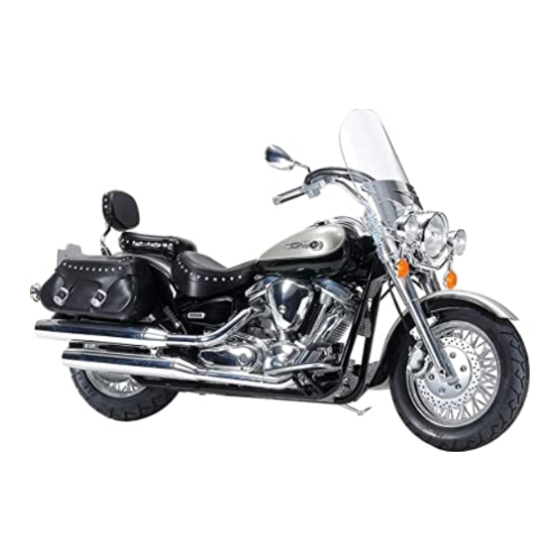
Page 20: Xv16A(C)/Xv16Ale(C)/Xv16As(C) Left View
D ESCRIPTION EAU00026 Road Star™ XV16A(C)/XV16ALE(C)/XV16AS(C) Left view (XV16A) 1. Shift pedal (page 3-7) 6. Helmet holder (page 3-12) 2. Starter (choke) knob (page 3-11) 7. Rear turn signal lights (page 6-37) 3. Fuel cock (page 3-10) 8. Tail/brake light (page 6-37) 4. -
Page 21: Xv16A(C)/Xv16Ale(C)/Xv16As(C) Right View
DESCRIPTION Road Star™ XV16A(C)/XV16ALE(C)/XV16AS(C) Right view (XV16A) 10. Passenger footrest 16. Brake pedal (page 3-8) 11. Passenger seat 17. Rider footrest 12. Fuel tank (page 3-9) 18. Shock absorber spring preload 13. Fuel tank cap (page 3-8) adjusting nut (page 3-15) 14. -
Page 22: Xv16At(C)/Xv16Atle(C) Left View
DESCRIPTION Road Star™/Silverado™ XV16AT(C)/XV16ATLE(C) Left view (XV16AT) 1. Shift pedal (page 3-7) 6. Helmet holder (page 3-12) 2. Starter (choke) knob (page 3-11) 7. Rear turn signal lights (page 6-37) 3. Fuel cock (page 3-10) 8. Tail/brake light (page 6-37) 4. -
Page 23: Xv16At(C)/Xv16Atle(C) Right View
DESCRIPTION Road Star™/Silverado™ XV16AT(C)/XV16ATLE(C) Right view (XV16AT) 11. Passenger seat 17. Brake pedal (page 3-8) 12. Fuel tank (page 3-9) 18. Rider footrest 13. Fuel tank cap (page 3-8) 19. Shock absorber spring preload 14. Windshield (page 3-13) adjusting nut (page 3-15) 15. -
Page 24: Xv16A(C)/Xv16Ale(C)/Xv16As(C)/Xv16At(C)/Xv16Atle(C) Controls And Instruments
DESCRIPTION Road Star™/Road Star™ Silverado™ XV16A(C)/XV16ALE(C)/XV16AS(C)/XV16AT(C)/XV16ATLE(C) Controls and instruments XV16A(C)/XV16ALE(C)/XV16AS(C) XV16AT(C)/XV16ATLE(C) (XV16A) (XV16AT) 1. Clutch lever (page 3-7) 5. Right handlebar switches (page 3-6) 2. Left handlebar switches (page 3-6) 6. Throttle grip (page 6-17) 3. Speedometer unit (page 3-3) 7. -
Page 25: Instrument And Control Functions
INSTRUMENT AND CONTROL FUNCTIONS Main switch/steering lock ........3-1 Fuel ..............3-9 Indicator and warning lights ........3-2 Fuel cock ............3-10 Speedometer unit ..........3-3 Starter (choke) knob ......... 3-11 Self-diagnosis device ...........3-4 Locking the steering with a padlock ....3-11 Fuel gauge ............3-4 Rider seat ............ -
Page 26: Main Switch/Steering Lock
I NSTRUMENT AND CONTROL FUNCTIONS EAU00027 1. Push. 2. Turn. EAU00029 EAU00040 Main switch/steering lock LOCK EW000016 The steering is locked, and all electrical WARNING The main switch/steering lock controls systems are off. The key can be the ignition and lighting systems, and is Never turn the key to “OFF”... -
Page 27: Instrument And Control Functions
0.9 US gal (0.8 Imp gal, 3.5 L). When the engine is defective. When this oc- this occurs, turn the fuel cock lever to curs, have a Yamaha dealer check the the “RES” position and refuel as soon self-diagnosis system. -
Page 28: Speedometer Unit
INSTRUMENT AND CONTROL FUNCTIONS Pushing the mode button (left) switch- es the display between the odometer mode “ODO” and the tripmeter modes “TRIP A” and “TRIP B” in the following order: CB-27E TRIP A TRIP B 1. Odometer/tripmeter/clock 2. Speedometer To reset a tripmeter, select it by push- 3. -
Page 29: Self-Diagnosis Device
“E”, refuel as soon as possible. come on or the fuel level warning light NOTE: will flash. If this occurs, have a Yamaha Do not allow the fuel tank to empty it- dealer check the motorcycle. self completely. -
Page 30: Clock
INSTRUMENT AND CONTROL FUNCTIONS 4. Push the right button to change the hours. 5. Push the left button and only the minute display will flash. 1. Clock 2. Set button 6. Push the right button to change To set the clock: 3. -
Page 31: Handlebar Switches
INSTRUMENT AND CONTROL FUNCTIONS Since this model is equipped with a self-canceling system, the turn signal lights will self-cancel after the motor- cycle has traveled both about 150 m (490 ft) and for approximately 15 sec- onds. However, the turn signal lights can also be canceled manually by pushing the switch in after it has re- turned to the center position. -
Page 32: Clutch Lever
INSTRUMENT AND CONTROL FUNCTIONS 1. Clutch lever 1. Shift pedal 1. Brake lever EAU00152 EAU01215 EAU00158 Clutch lever Shift pedal Brake lever The clutch lever is located at the left The shift pedal is located on the left The brake lever is located at the right handlebar grip. -
Page 33: Brake Pedal
INSTRUMENT AND CONTROL FUNCTIONS To install the fuel tank cap 1. Insert the fuel tank cap into the tank opening with the key inserted in the lock and with the “ ” mark facing forward. 2. Turn the key counterclockwise to the original position, remove it, and then close the lock cover. -
Page 34: Fuel
INSTRUMENT AND CONTROL FUNCTIONS EAU00185 Your Yamaha engine has been de- CAUTION: signed to use regular unleaded gaso- Immediately wipe off spilled fuel line with a pump octane number with a clean, dry, soft cloth, since [(R+M)/2] of 86 or higher, or a research fuel may deteriorate painted surfac- octane number of 91 or higher. -
Page 35: Fuel Cock
INSTRUMENT AND CONTROL FUNCTIONS OFF: closed position ON: normal position RES: reserve position Pointed end positioned over “OFF” Pointed end positioned over “ON” Pointed end positioned over “RES” EAU03050 Fuel cock With the lever in this position, fuel flows This indicates reserve. If you run out of The fuel cock supplies fuel from the to the carburetor. -
Page 36: Starter (Choke) Knob
INSTRUMENT AND CONTROL FUNCTIONS EAU04038 EAU03372 EAU03785* Starter (choke) knob “ ” Locking the steering with a Rider seat Starting a cold engine requires a richer padlock air-fuel mixture, which is supplied by To remove the rider seat In addition to the main switch/steering the starter (choke). -
Page 37: Helmet Holder
INSTRUMENT AND CONTROL FUNCTIONS EW000030 WARNING Never ride with a helmet attached to the helmet holder, since the helmet may hit objects, causing loss of control and possibly an accident. To release the helmet from the hel- met holder 1. Projection 1. -
Page 38: Windshield [Xv16At(C)/Xv16Atle(C)]
INSTRUMENT AND CONTROL FUNCTIONS 4. Loosen the screws holding the windshield cover located above the headlight, position the cover close to the headlight without touching it, and then tighten the screws. 1. Windshield 1. Headlight cover 2. Bolt (× 4) 2. -
Page 39: Saddlebags [Xv16At(C)/Xv16Atle(C)]
INSTRUMENT AND CONTROL FUNCTIONS EW000134 WARNING After adjusting the windshield: ● Securely tighten the windshield bolts. ● Turn the handlebar to the left and right to make sure that the handlebar is not obstructed and that the windshield does not contact any other parts. -
Page 40: Adjusting The Shock Absorber Assembly
INSTRUMENT AND CONTROL FUNCTIONS 1. Locknut 1. Special wrench A. Distance A 2. Spring preload adjusting nut 2. To increase the spring preload NOTE: EAU03591 and thereby harden the suspen- The spring preload setting is deter- Adjusting the shock absorber sion, turn the adjusting nut in di- mined by measuring distance A, shown assembly... - Page 41 EC000018 CAUTION: will result in poor damping per- Always tighten the locknut against formance. the adjusting nut, and then tighten ● Always have a Yamaha dealer the locknut to the specified torque. service the shock absorber. 3-16...
-
Page 42: Sidestand
It cuts the running engine when check this system regularly as de- the transmission is in gear and the scribed below and have a Yamaha sidestand is moved down. dealer repair it if it does not function Periodically check the operation of the properly. - Page 43 5. Push the start switch. Does the engine start? The neutral switch may be defective. The motorcycle should not be ridden until checked by a Yamaha dealer. With the engine still running: 6. Move the sidestand up. 7. Keep the clutch lever pulled.
-
Page 45: Pre-Operation Checks
PRE-OPERATION CHECKS Pre-operation check list ..............4-1... -
Page 46: Pre-Operation Check List
• Check lever free play. • Adjust if necessary. • Make sure that operation is smooth. • Check cable free play. Throttle grip 6-17 • If necessary, have Yamaha dealer adjust cable free play and lubricate cable and grip housing. - Page 47 • Check operation of ignition circuit cut-off system. Sidestand switch 3-17 • If system is defective, have Yamaha dealer check vehicle. NOTE: Pre-operation checks should be made each time the motorcycle is used. Such an inspection can be accomplished in a very short time;...
-
Page 49: Operation And Important Riding Points
OPERATION AND IMPORTANT RIDING POINTS Starting and warming up a cold engine ..........5-1 Starting a warm engine ..............5-3 Shifting ....................5-3 Engine break-in ................. 5-5 Parking ....................5-6... - Page 50 Consult check the function of the igni- ● Make sure not to put anything a Yamaha dealer regarding any tion circuit cut-off system ac- near the battery and its termi- control or function that you do cording...
- Page 51 50°F (10°C) re- Yamaha dealer check the electrical serve the battery. Do not crank the en- quire about 35 seconds with the starter circuit.
- Page 52 OPERATION AND IMPORTANT RIDING POINTS EAU01258 EC000048 Starting a warm engine CAUTION: Follow the same procedure as for start- ● Even with the transmission in ing a cold engine with the exception the neutral position, do not that the starter (choke) is not required coast for long periods of time when the engine is warm.
- Page 53 OPERATION AND IMPORTANT RIDING POINTS EAU02988* EAU02974 To start out and accelerate Recommended shift points 1. Pull the clutch lever to disengage The recommended shift points during the clutch. acceleration and deceleration are 2. Shift the transmission into first shown in the table below. gear.
-
Page 54: Engine Break-In
Since the engine is brand new, do not immediately have a Yamaha dealer put an excessive load on it for the first check the vehicle. 1,000 mi (1,600 km). The various parts... - Page 55 OPERATION AND IMPORTANT RIDING POINTS EAU00457 Parking When parking, stop the engine, re- move the key from the main switch, and then turn the fuel cock lever to “OFF”. EW000058 WARNING ● Since the engine and exhaust system can become very hot, park in a place where pedestri- ans or children are not likely to touch them.
-
Page 57: Periodic Maintenance And Minor Repair
PERIODIC MAINTENANCE AND MINOR REPAIR Periodic maintenance ..........6-1 Checking the brake fluid level ......6-24 Owner’s tool kit ............6-2 Changing the brake fluid ........6-25 Periodic maintenance chart for the emission Drive belt slack ..........6-25 control system ...........6-3 Checking and lubricating the throttle grip and General maintenance and lubrication chart ..6-4 cable ............... -
Page 58: Periodic Maintenance
SERVICE. ESPE- If you are not familiar with motor- CIALLY IMPORTANT cycle maintenance work, have a MAINTENANCE SERVICES RELAT- Yamaha dealer do it for you. EMISSIONS CONTROL. THESE CONTROLS ONLY FUNCTION TO ENSURE CLEANER AIR, BUT ARE ALSO VITAL TO PROPER ENGINE OPERATION AND MAXIMUM PERFORMANCE. -
Page 59: Owner's Tool Kit
PERIODIC MAINTENANCE AND MINOR REPAIR NOTE: If you do not have the tools or experi- ence required for a particular job, have a Yamaha dealer perform it for you. EW000062 WARNING Modifications approved Yamaha may cause loss of perfor- mance, excessive emissions, and 1. -
Page 60: Periodic Maintenance Chart For The Emission Control System
• Adjust cable free play. Evaporative Emission control • Check control system for damage. √ √ system (For • Replace if necessary. California only) * Since these items require special tools, data and technical skills, have a Yamaha dealer perform the service. -
Page 61: General Maintenance And Lubrication Chart
Rear arm pivot Medium weight wheel √ • Moderately repack every Repack bearing bearing grease 16,000 mi (25,000 km) or 24 months. * Since these items require special tools, data and technical skills, have a Yamaha dealer perform the service. - Page 62 • Apply grease lightly. sion link pivots grease • Check for belt tension √ Drive belt Every 2,500 mi (4,000 km) • Adjust if necessary * Since these items require special tools, data and technical skills, have a Yamaha dealer perform the service.
- Page 63 PERIODIC MAINTENANCE AND MINOR REPAIR EAU03907 NOTE: From 24,000 mi (37,000 km) or 36 months, repeat the maintenance intervals starting from 4,000 mi (7,000 km) or 6 months. EAU03057 NOTE: ● The air filter needs more frequent service if you are riding in unusually wet or dusty areas. ●...
-
Page 64: Removing And Installing The Panel
PERIODIC MAINTENANCE AND MINOR REPAIR 1. Panel A 1. Bolt EAU01777 EAU00491 To install the panel Removing and installing the Panel A Place the panel in the original position, To remove the panel panel and then install the bolt. Remove the bolt, and then pull the pan- The panel shown above needs to be el off as shown. -
Page 65: Checking The Spark Plugs
NOTE: problems yourself. Instead, have a If a torque wrench is not available when EAU01639 Yamaha dealer check the motorcycle. Checking the spark plugs installing a spark plug, a good estimate If a spark plug shows signs of electrode The spark plugs are important engine of the correct torque is 1/4–1/2 turn... -
Page 66: Canister (For California Only)
PERIODIC MAINTENANCE AND MINOR REPAIR ECA00021 CAUTION: Do not use any tools to remove or install the spark plug cap, otherwise the ignition coil coupler may get damaged. The spark plug cap may be difficult to remove because the rubber seal on the end of the cap fits tightly. - Page 67 PERIODIC MAINTENANCE AND MINOR REPAIR NOTE: NOTE: Make sure that the motorcycle is posi- When adding oil, be careful not to over- tioned straight up when checking the oil fill the engine; the oil level rises faster level. A slight tilt to the side can result in starting from the half level portion on a false reading.
- Page 68 6. Remove the oil filter cartridge with an oil filter wrench. NOTE: An oil filter wrench is available at a Yamaha dealer. 1. Engine oil drain bolt (oil tank) 1. Engine oil drain bolt (crankcase) To change the engine oil (with or 7.
- Page 69 PERIODIC MAINTENANCE AND MINOR REPAIR 12. Remove the engine oil filler cap, ECA00133 CAUTION: and then gradually fill the oil tank ● In order to prevent clutch slip- with the remaining oil quantity page (since the engine oil also while regularly checking the oil lubricates the clutch), do not level on the dipstick.
-
Page 70: Transfer Case Oil
PERIODIC MAINTENANCE AND MINOR REPAIR NOTE: Make sure that the motorcycle is posi- tioned straight up when checking the oil level. A slight tilt to the side can result in a false reading. 2. Remove the oil check bolt, and then check the oil level in the transfer case. - Page 71 PERIODIC MAINTENANCE AND MINOR REPAIR 5. Start the engine and let it idle for several minutes while checking the transfer case for oil leakage. If oil is leaking, immediately turn the engine off and check for the cause. 1. Transfer case oil level check hole 4.
-
Page 72: Cleaning The Air Filter Element
PERIODIC MAINTENANCE AND MINOR REPAIR 1. Bolt (× 4) 1. Air filter joint clamp screw 1. Screw (× 2) 2. Air filter case 2. Hose (× 2) 2. Loosen the air filter joint clamp 3. Air filter case cover EAU03707 screw, and then slightly pull the air Cleaning the air filter element 3. - Page 73 PERIODIC MAINTENANCE AND MINOR REPAIR 1. Screw (× 2) 1. Hose (× 2) 2. Hose 6. Lightly tap the air filter element to 9. Connect the hoses shown. 5. Remove the air filter element by remove most of the dust and dirt, 10.
-
Page 74: Adjusting The Carburetor
To prevent this adjustment. Therefore, carburetor ad- from occurring, the valve clearance justments should be left to Yamaha must be adjusted by a Yamaha dealer dealer, who has the necessary profes- at the intervals specified in the periodic sional knowledge and experience. -
Page 75: Tires
PERIODIC MAINTENANCE AND MINOR REPAIR rider, passenger, and accessories tribute the weight evenly from side (windshield, saddlebags, etc. if ap- to side. Properly adjust the suspen- proved for this model). sion for your load, and check the condition and pressure of your tires. CE-05E NEVER OVERLOAD YOUR MOTOR- Tire air pressure... - Page 76 After extensive tests, the tires men- form to the limits specified by the tioned below have been approved regulations of your own country. by Yamaha Motor Co., Ltd. for this model. No guarantee for handling characteristics can be given if tire 6-19...
-
Page 77: Spoke Wheels
If any dam- motorcycle should be designed spe- age is found, have a Yamaha cifically for this model, and they dealer replace the wheel. Do not must be securely mounted to main-... -
Page 78: Adjusting The Clutch Lever Free Play
PERIODIC MAINTENANCE AND MINOR REPAIR 1. Locknut 1. Clutch lever free play adjusting nut 1. Locknut 2. Clutch lever free play adjusting bolt 2. Locknut 2. Brake lever free play adjusting bolt c. Clutch lever free play c. Brake lever free play 3. -
Page 79: Adjusting The Brake Pedal Position
Periodically check the brake pedal posi- which may result in loss of con- tion and, if necessary, have a Yamaha trol and an accident. dealer adjust it. 6-22... -
Page 80: Adjusting The Rear Brake Light Switch
Yamaha dealer replace Turn the adjusting nut while holding the the brake pads as a set. rear brake light switch in place. To make the brake light come on earlier, turn the adjusting nut in direction a. -
Page 81: Checking The Brake Fluid Level
If the peared, have a Yamaha dealer replace brake level is low, be sure to check the Recommended brake fluid: DOT 4 the brake pads as a set. -
Page 82: Changing The Brake Fluid
Be careful that water does not en- EAU03976 Changing the brake fluid ter the brake fluid reservoir when Have a Yamaha dealer change the refilling. Water will significantly brake fluid at the intervals specified in lower the boiling point of the fluid the NOTE after the periodic mainte- and may result in vapor lock. - Page 83 NOTE: A belt tension gauge is available at a Yamaha dealer. 4. Calculate the drive belt slack by subtracting the measurement not- ed in step 2 from the measure- ment noted in step 3.
-
Page 84: Checking And Lubricating The Throttle Grip And Cable
PERIODIC MAINTENANCE AND MINOR REPAIR ECA00025 EAU04034 Checking and lubricating the CAUTION: throttle grip and cable Improper drive belt slack will over- The operation of the throttle grip should load the engine. Keep the drive belt be checked before each ride. In addi- slack within the specified range. -
Page 85: Checking And Lubricating The Brake And Shift Pedals
PERIODIC MAINTENANCE AND MINOR REPAIR EAU03370 Checking and lubricating the brake and shift pedals The operation of the brake and shift pedals should be checked before each ride, and the pedal pivots should be lu- bricated if necessary. Recommended lubricant: Lithium-soap-based grease (all-purpose grease) 6-28... -
Page 86: Checking And Lubricating The Brake And Clutch Levers
EW000113 Recommended lubricant: WARNING Lithium-soap-based grease If the sidestand does not move up (all-purpose grease) and down smoothly, have a Yamaha dealer check or repair it. Recommended lubricant: Lithium-soap-based grease (all-purpose grease) 6-29... -
Page 87: Checking The Front Fork
EC000098 CAUTION: If any damage is found or the front fork does not operate smoothly, have a Yamaha dealer check or re- pair it. 6-30... -
Page 88: Checking The Steering
WARNING ward and backward. If any free Securely support the motorcycle so play can be felt, have a Yamaha that there is no danger of it falling dealer check or repair the steering. over. -
Page 89: Battery
PERIODIC MAINTENANCE AND MINOR REPAIR EW000116 To charge the battery WARNING Have a Yamaha dealer charge the bat- ● Electrolyte is poisonous and tery as soon as possible if it seems to dangerous since it contains sul- have discharged. Keep in mind that the... -
Page 90: Replacing The Fuses
(MF) bat- 6. Spare fuse (× 3) contains the fuses for the individual cir- tery charger, have a Yamaha cuits, are located behind panel A. (See If a fuse is blown, replace it as follows. dealer charge your battery. - Page 91 1. Main fuse 2. Spare main fuse check if the device operates. 4. If the fuse immediately blows Specified fuses: again, have a Yamaha dealer Main fuse: 30 A check the electrical system. Headlight fuse: 15 A...
-
Page 92: Replacing The Headlight Bulb
PERIODIC MAINTENANCE AND MINOR REPAIR 1. Screw (× 2) 1. Headlight coupler 1. Headlight bulb holder 2. Headlight bulb cover EAU04189 3. Unhook the headlight bulb holder, Replacing the headlight bulb 2. Disconnect the headlight coupler, and then remove the defective This motorcycle is equipped with a and then remove the bulb cover. - Page 93 6. Install the headlight unit by install- from a lit headlight bulb, and do not ing the screws. touch the bulb until it has cooled 7. Have a Yamaha dealer adjust the down. headlight beam if necessary. 4. Place a new headlight bulb into position, and then secure it with the bulb holder.
-
Page 94: Replacing A Turn Signal Light Bulb Or The Tail/Brake Light Bulb
PERIODIC MAINTENANCE AND MINOR REPAIR EAU01579 Supporting the motorcycle Since this model is not equipped with a centerstand, follow these precautions when removing the front and rear wheel or performing other mainte- nance requiring the motorcycle to stand upright. Check that the motor- cycle is in a stable and level position 1. -
Page 95: Troubleshooting
However, should your motorcycle require any repair, take it to a Yamaha dealer, whose skilled technicians have the necessary tools, experience, and know-how to service the motorcycle properly. -
Page 96: Troubleshooting Chart
Remove the spark plugs and check the electrodes. The engine does not start. Have a Yamaha dealer check the vehicle. Check the battery. 4. Battery The engine turns over The battery is good. -
Page 97: Motorcycle Care And Storage
MOTORCYCLE CARE AND STORAGE Care ....................7-1 Storage ....................7-5... - Page 98 M OTORCYCLE CARE AND STORAGE EAU03708 Before cleaning Cleaning 1. Cover the muffler outlets with plas- ECA00010 CAUTION: tic bags after the engine has ● Avoid using strong acidic wheel cooled down. cleaners, especially on spoked 2. Make sure that all caps and covers wheels.
- Page 99 For roads. shield to make sure that it does additional cleaning, use Yamaha Wind- not leave any marks. If the wind- NOTE: shield Cleaner or other quality cleaner.
- Page 100 3. To prevent corrosion, it is recom- NOTE: warm water and a mild deter- mended to apply a corrosion pro- Consult a Yamaha dealer for advice on gent. tection spray metal, what products to use.
- Page 101 MOTORCYCLE CARE AND STORAGE Exposure to the elements can dry out the leather over time. Therefore, an oc- casional application of a good quality mink oil is recommended to restore the leather and lift its water resistance. Make sure that the saddlebags are clean and dry before applying the mink oil.
- Page 102 MOTORCYCLE CARE AND STORAGE Long-term a. Remove the spark plug caps and Before storing your motorcycle for spark plugs. several months: b. Pour a teaspoonful of engine oil 1. Follow all the instructions in the into each spark plug bore. “Care”...
- Page 103 MOTORCYCLE CARE AND STORAGE 6. Lubricate all control cables and NOTE: Make any necessary repairs before the pivoting points of all levers and storing the motorcycle. pedals as well as of the sidestand/ centerstand. 7. Check and, if necessary, correct the tire air pressure, and then lift the motorcycle so that both of its wheels are off the ground.
-
Page 105: Specifications
SPECIFICATIONS Specifications ..................8-1... - Page 106 S PECIFICATIONS EAU01038 Specifications CS-01E Model XV16A(C)/XV16ALE(C)/ Compression ratio 8.3:1 XV16AS(C)/XV16AT(C)/ Starting system Electric starter XV16ATLE(C) Lubrication system Dry sump Dimensions Engine oil Overall length 98.4 in (2,500 mm) Type Overall width 38.6 in (980 mm) 110 130 ˚F Overall height XV16A(C)/XV16ALE(C)/ 44.9 in (1,140 mm) YAMALUBE 4 (10W-30)
- Page 107 SPECIFICATIONS Quantity Transmission Without oil filter cartridge Primary reduction system Spur gear replacement 3.9 US qt (3.3 lmp qt, 3.7 L) Primary reduction ratio 1.532 With oil filter cartridge Secondary reduction system Belt replacement 4.3 US qt (3.6 lmp qt, 4.1 L) Secondary reduction ratio 2.320 Total amount (dry engine)
- Page 108 SPECIFICATIONS Rear Rear Type Tube tire Type Spoke wheel Size 150/80B-16 71H Size 16 × MT 3.50 150/80B-16 M/C 71H 16 M/C × MT 3.50 Manufacturer/ Brakes model Dunlop / D404 Front Bridgestone / G702 Type Dual disc brake Maximum load* Operation Right hand XV16A(C)/XV16ALE(C)/...
- Page 109 SPECIFICATIONS Electrical Fuses Ignition system Transistorized coil ignition Main fuse 30 A (digital) Ignition fuse 15 A Charging system Signaling system fuse 10 A Type A.C. magneto Headlight fuse 15 A Standard output 14 V, 21 A @ 5,000 r/min Carburetor heater fuse 10 A Battery...
-
Page 111: Consumer Information
Vehicle identification number ............. 9-1 Model label ..................9-2 Reporting safety defects ..............9-3 Motorcycle noise regulation .............. 9-4 Maintenance record ................9-5 YAMAHA MOTOR CORPORATION, U.S.A. STREET AND ENDURO MOTORCYCLE LIMITED WARRANTY ......9-7 YAMAHA EXTENDED SERVICE (Y.E.S.) ......... 9-9... -
Page 112: Identification Numbers
Record the key identification number, vehicle identification number and mod- el label information in the spaces pro- vided below for assistance when ordering spare parts from a Yamaha dealer or for reference in case the vehi- cle is stolen. 1. Key identification number 1. -
Page 113: Model Label
The model label is affixed to the frame under the rider seat. (See page 3-11 for rider seat removal and installation pro- cedures.) Record the information on this label in the space provided. This in- formation will be needed when ordering spare parts from a Yamaha dealer. -
Page 114: Reporting Safety Defects
If you believe that your vehicle has a defect which could cause a crash or could cause injury or death, you should immedi- ately inform the National Highway Traffic Safety Administration (NHTSA) in addition to notifying Yamaha Motor Corporation, U.S.A. If NHTSA receives similar complaints, it may open an investigation, and if it finds that a safety defect exists in a group of vehicles, it may order a recall and remedy campaign. -
Page 115: Motorcycle Noise Regulation
CONSUMER INFORMATION EAU01053 Motorcycle noise regulation TAMPERING WITH NOISE CONTROL SYSTEM PROHIBITED: Federal law prohibits the following acts or the causing thereof: (1) The removal or rendering inoperative by any person other than for purposes of maintenance, repair, or replacement of any device or element of design incorporated into any new ve- hicle for the purpose of noise control prior to its sale or delivery to the ultimate purchaser or while it is in use or (2) the use of the vehicle after such device or element of design has been removed or rendered inoperative by any person. -
Page 116: Maintenance Record
CONSUMER INFORMATION EAU01325 Maintenance record Copies of work orders and/or receipts for parts purchased and installed on your motorcycle will be required to document that maintenance has been completed in accordance with the emissions warranty. The chart below is printed only as a reminder that maintenance work is required. - Page 117 CONSUMER INFORMATION Maintenance Date of Servicing dealer Mileage Remarks interval service name and address 28,000 mi (43,000 km) or 42 months 32,000 mi (49,000 km) or 48 months 36,000 mi (55,000 km) or 54 months 40,000 mi (61,000 km) or 60 months...
-
Page 118: Yamaha Motor Corporation, U.s.a. Street And Enduro Motorcycle Limited Warranty
CONSUMER INFORMATION EAU02918 YAMAHA MOTOR CORPORATION, U.S.A. STREET AND ENDURO MOTORCYCLE LIMITED WARRANTY... - Page 119 CONSUMER INFORMATION...
-
Page 120: Yamaha Extended Service (Y.e.s.)
CONSUMER INFORMATION EAU01063 YAMAHA EXTENDED SERVICE (Y.E.S.) - Page 121 CONSUMER INFORMATION 9-10...
- Page 122 I NDEX 1 0 - Accessories and replacement parts ..6-20 Engine break-in ........5-5 Main switch/steering lock ......3-1 Air filter element, cleaning ......6-15 Engine oil and oil filter cartridge ....6-9 Maintenance and lubrication, periodic ..6-4 Engine stop switch........3-6 Maintenance, emission control system..6-3 Engine trouble warning light ....
- Page 123 INDEX Spark plugs, checking ......6-8 Specifications .......... 8-1 Warranty, extended......... 9-9 Speedometer unit ........3-3 Warranty limited ........9-7 Starter (choke) knob ......3-11 Wheel bearings, checking ..... 6-31 Starting and warming up a cold engine..5-1 Wheels..........6-20 Starting a warm engine......
- Page 126 YAMAHA MOTOR CO., LTD. PRINTED ON RECYCLED PAPER PRINTED IN JAPAN 2002.08-0.3×1 CR...
Need help?
Do you have a question about the Road Star XV16ARC and is the answer not in the manual?
Questions and answers