Table of Contents
Advertisement
Advertisement
Table of Contents

Related Manuals for Uwatec SMART TEC


Summary of Contents for Uwatec SMART TEC
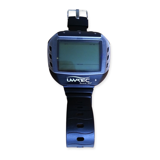
- Page 1 Operating Manual Smart TEC ® SWISS MADE BY UWATEC AG...
-
Page 2: Safety Considerations
• The danger of nitrogen narcosis has to be taken into consideration. Smart TEC gives no warning about this. • On all dives with Smart TEC, make a safety stop for at least 3 minutes at 5 metres (15 feet). • All divers using dive computers to plan dives and indicate or determine decompression status must use their own computer, which they take with them on all dives. - Page 3 • After finishing the decompression or at the end of a no-stop dive, the final stage of the ascent should be as slow as possible. • You MUST be familiar with all signs and symptoms of decompression sickness before using Smart TEC! Seek IMMEDIATE treatment for decompression sickness should any of these signs or symptoms occur after a dive! There is a direct correlation between the effectiveness of treatment and the delay bet- ween the onset of symptoms and the treatment for decompression sickness.
-
Page 4: Introduction
Further information on UWATEC Smart dive computers and other products by UWATEC can be found on our web page at www.uwatec.com. To make this manual easier to read we will use the term 'TEC' as an abbreviation for 'UWATEC Smart TEC diving computer' throughout this booklet. -
Page 5: Quick Reference / Operating Scheme
Quick reference mix icon (input) Microbubble level icon (input / MB level reduced) Do not fly Icon Gauge icon Do not dive icon Logbook icon Microbubble warning Dive planner icon Dive time / No-fly time / SOS duration Current depth Service icon Icon for stopwatch and safety stop CNS O... -
Page 6: Table Of Contents
Setting up Smart TEC __________________________________12 4.1 Mounting of transmitter __________________________________12 4.2 Pairing of transmitter and dive computer __________________________________13 III Diving with Smart TEC __________________________________15 Terminology / Symbols __________________________________15 1.1 General terminology / Display during no-stop phase __________________________________15 1.2 Display during decompression phase /... - Page 7 List of chapters Diving in mountain lakes __________________________________25 6.1 Altitude ranges __________________________________25 6.2 Prohibited altitude __________________________________25 6.3 Decompression dives in mountain lakes __________________________________25 IV Gauge mode __________________________________26 V Diving with microbubble levels (MB) __________________________________28 Comparison of dives with MB level L0 and MB level L5 __________________________________28 Terminology __________________________________29...
-
Page 8: System And Operation
® The SmartTRAK CD software is included with the TEC Package. Infrared interfaces are available in PC sto- res. A list of recommended interfaces is available on the UWATEC homepage (www.uwatec.com). Smart TEC SmartTRAK Infrared port Infrared Interface... -
Page 9: Smarttrak
II System and operation Push buttons To use the push buttons TEC must be switched on. Operation of the push buttons is divided into «press» and «press and hold (1 second)». The push buttons activate the following functions: Select the gas mixture (press) Confirm the gas mixture (press and hold) Activate the timer for safety stops (dive mode only, in depths <... -
Page 10: Switching On The Display
2 Operation 2.3 Switching on the display • automatically, on submerging in water or when adaptation to atmospheric pressure is necessary; • manually, by bridging contacts on housing (B-E). • When TEC is in state of rest no information is displayed but the atmospheric pressure is continuously monitored. -
Page 11: Active Backlight
2 Operation / 3 SOS mode 2.6 Active backlight The display of TEC can be illuminated both on the surface and underwater. The backlight can be activated by pushing and holding button for 1 second. The light will turn off automatically after 8 seconds or after the time selected via SmartTRAK. -
Page 12: Setting Up Smart Tec
4 Setting up Smart TEC (transmitter and dive computer) 4.1 Mounting of transmitter Each individual pressure tank requires a separate transmitter. The transmitter is mounted at the high pressure (HP) outlet of the regulator’s first stage before the first dive. -
Page 13: Pairing Of Transmitter And Dive Computer
4 Setting up (transmitter and dive computer) 4.2 Pairing of transmitter and dive computer To receive the data of the transmitters, each transmitter must be assigned to one tank symbol and paired with TEC. Pairing is necessary: • before the first use of TEC with the transmitter; •... - Page 14 4 Setting up Smart TEC • Pairing of transmitter and dive computer may already be carried out at home and need only be executed once, before the first use. • A transmitter can only be paired with a single tank symbol at a time. If you try to pair the same transmitter with a second tank symbol, the first pairing will automatically be deleted.
-
Page 15: Diving With Smart Tec
III Diving with Smart TEC 1 Terminology / Symbols The information on the display of TEC varies depending on the kind of dive and the dive phase. For information about diving with microbubble levels (MB levels) see chapter V ->28. Specific features of "Diving with more than one gas mixture", are descri- bed in chapter VI ->... -
Page 16: Nitrox Information (O Information)
1 Terminology / Symbols 1.3 Nitrox information (O information) For dives with compressed air in normal recreational diving, nitrogen is the decisive gas for the decom- pression calculations. When diving with Nitrox, the risk of oxygen toxicity rises with the increase of the frac- tion of oxygen and the increase of depth and can limit dive time and the maximum depth. -
Page 17: Attention Messages And Alarms
2 Attention messages and alarms TEC draws the diver’s attention to certain situations and warns the diver of unsafe diving practices. Atten- tion messages and alarms are always visual and audible under water, only visual at the surface except the decompression alarm. -
Page 18: Preparation For The Dive
3 Preparation for the dive 3.1 Setting the gas mixture and MOD Before every dive and after changing the tank, make sure that the settings for the gas mixtures correspond with the current mixtures used. An incorrect setting cau- WARNING ses TEC to miscalculate this particular dive. -
Page 19: Functions During The Dive
4 Functions during the dive 4.1 Immersion After immersion, starting at a depth of about 0.8 m (3 ft), TEC automatically selects gas mixture 1, all diving functions are monitored, i.e. depth and dive time displayed, maximum depth stored, saturation of tissues calculated, no-stop time or decompression prognosis determined, ascent rate controlled and dis- played and the correctness of the decompression procedure supervised. -
Page 20: Maximum Operating Depth (Mod)
4 Functions during the dive The prescribed ascent rate must be observed at all times! Exceeding the pre- WARNING scribed ascent rate can lead to microbubbles in the arterial circulation which can lead to serious injury or death due to decompression sickness. •... -
Page 21: Oxygen Toxicity
4 Functions during the dive 4.8 Oxygen toxicity (CNS O TEC calculates oxygen toxicity from depth values, time and the gas mixture and CNS O displays it in the location of the ascent rate. The toxicity is expressed in 1% increments of a maximum tolerated value (O clock). -
Page 22: Remaining Bottom Time (Rbt)
4 Functions during the dive 4.10 Remaining Bottom Time (RBT) RBT is the time left at the current depth until the point of time when the ascent must be started. The RBT is calculated on the basis of the current tank pressure, breathing rate, the temperature, and the dive data so far recorded. -
Page 23: Safety Stop Timer
4 Functions during the dive Decompression values On entering the decompression phase, the arrow disappears, the NO STOP arrow appears and an attention beep goes off. Right beside the DECOSTOP arrow, the deepest decompression stage in metres (feet) is displayed. Next to the decompression stop depth, the decompression stop duration of the dis- CNS O played stage appears in minutes. -
Page 24: Functions At The Surface
5 Functions at the surface 5.1 End of a dive After reaching the surface (<0.8 m/3 ft) TEC remains in dive mode for 5 minutes. The delay allows for surfacing for a short period for orientation. After 5 minutes the dive is closed and it is entered into the logbook. For the calculations of the desaturation and no-fly time it is assumed that the WARNING diver breathes air while on the surface. -
Page 25: Diving In Mountain Lakes
6 Diving in mountain lakes 6.1 Altitude ranges TEC measures the atmospheric pressure every 60 seconds even while the dis- play is switched off. If the computer detects a sufficient increase in altitude, it switches on automatically and indicates the new altitude range (1-4) and the desaturation time. -
Page 26: Gauge Mode
IV Gauge mode In gauge mode ALL audible and visual alarms and attention messages are WARNING turned off. This includes ascent speed, low tank pressure and interrupted signal from transmitter. In gauge mode TEC will display depth, dive time and tank pressure, the maximum depth is stored, ascent rate and tank pressure are monitored. - Page 27 IV Gauge mode Stopwatch In gauge mode, after immersion, TEC will automatically monitor the dive time and at the same time activate the stopwatch. If the gauge symbol and "on" are displayed (-> 26, point 1) the stopwatch can also be activated at the surfa- ce by pressing .
-
Page 28: Diving With Microbubble Levels (Mb)
This works contrary to the formation of the microbub- bles and increases the safety. Smart TEC features 6 microbubble levels (L0-L5). Level L0 corresponds to UWATEC's well-known decompression model ZH-L8 ADT and does not require level stops due to microbubble formation. Levels L1 to L5 offer additional protection from microbubble formation with level L5 offering the highest protection. -
Page 29: Terminology
2 Terminology This chapter will exclusively deal with terminology and display features used while diving with MB levels. All other features are described in chapter III (page 15). 2.1 Display during microbubble (MB) no-stop phase MB no-stop phase Level stop phase MB level Dive phase during which surfacing is activated... -
Page 30: Preparation For A Dive With Microbubble Levels (Mb Levels)
3 Preparation for a dive with microbubble levels (MB levels) 3.1 Setting the MB level To change the MB level TEC must be in user mode. 1. Bridge contacts B and + or B and – until the symbol for MB levels appears. 2. -
Page 31: Total Time Of Ascent
4 Functions during the dive with microbubble levels The attention message "Level stop ignored" is 4 sec activated if the requested level stop is not observed. WARNING An attention beep* goes off, the arrow LEVELSTOP CNS O the depth and duration of the ignored level stop begin flashing. -
Page 32: Level Stop And Deco Stop
The following chapter deals with the characteristics of diving with more than one gas mixture. Smart TEC enables you to use up to three different gas mixtures during the same dive. To measure the tank pressure, each tank requires an individual transmitter. Tank 1 contains the bottom mix, tank 2 contains the travel mix and tank D contains the deco mix. - Page 33 Diving with more than one gas mixture Preparation for a dive with several gas mixtures Before the dive, all transmitters in use must be paired with TEC, the fraction of oxygen must be entered for each tank and the depth for changing the gas mixture must be set for tanks 2 and D. Setting the gas mixture and the depth for changing the gas mixture During dives with more than one gas mixture the bottom mix Range of O...
- Page 34 Diving with more than one gas mixture Switching off gas mixtures Tanks which are not going to be used during the next dive (even though their fraction of oxygen has been defined) must be "switched off". This is achieved by switching off the appropriate gas mixture at TEC. Gas mixtures which have been switched off cannot be selected during the dive and TEC will ignore their transmitters.
- Page 35 Diving with more than one gas mixture Changing the gas mixture After immersion, TEC automatically selects gas mixture 1. 4 sec DECO STOP If during the ascent a diver reaches the depth requiring a change of gas mixture (MOD gas mix- WARNING ture D or 2), the imminent change is brought to the diver’s attention by an audible attention signal...
- Page 36 Diving with more than one gas mixture 7. Above MOD for 100%, missed switch: now TEC-3 gives the same decompression prognosis as TEC- 1. TEC-4 gives the same decompression prognosis as TEC-2. 8. Again below the MOD for 100%: TEC-3 and TEC-4 again show credit for the presence of the 100% mix in their calculations 9.
-
Page 37: Dive Planner
VII Dive planner TEC has a dive planner which allows the planning of no-stop dives as well as decompression dives with freely determinable surface intervals and with up to three different gas mixtures. Basis of the planning: • selected fraction of oxygen and MOD of all active gas mixtures •... -
Page 38: Planning A Decompression Dive
VII Dive planner 2 Planning a decompression dive 1. Activate the dive planner for a no-stop dive ->37. 2. Wait until the desired depth appears, then switch into decompression plan- NO STOP ning by bridging contacts B and E. TEC shows the bottom time (no-stop time + 1 minute) and the appropriate decompression information or level stop data respectively. -
Page 39: Logbook
VIII Logbook VIII 1 Survey A dive is entered in the logbook if the dive time is longer than 2 minutes. TEC records the profiles of about 100 hours of diving. This information can be transferred to a PC with the standard infrared interface (IrDA) and the Windows software SmartTRAK. -
Page 40: Appendix
IX Appendix 1 Technical information Operating altitude: with decompression information: sea level up to approx. 4000 m (13120ft); w/o decompression, w/o RBT information: usable in gauge mode (at any altitude) Max. displayed depth: 120m (395 ft), resolution between 0.8 m and 99.9 m: 0.1 m, >99.9 m: 1m The resolution in feet is always 1 foot •... - Page 41 IX Appendix Never touch the metal surface of the battery with bare fingers. WARNING The two battery poles must never be short circuited. Transmitter Battery Transmitter Cap CR2450 HP port o-ring 8.73 x 1.78 mm Transmitter screws ® KA 30 x 16 mm Transmitter cap o-ring 26.00 x 2.00 mm Procedure:...
-
Page 42: Conversion Of Tank Pressure
2030 1740 220 230 2175 2320 2465 2610 2755 2900 3045 3190 3335 psi Display Smart TEC 4 Warranty The warranty only covers dive computers which have been bought from an authorised SCUBAPRO UWATEC retailer. The warranty is given for a period of 2 years. -
Page 43: Fcc
IX Appendix Excluded are faults or defects due to: • excessive wear and tear; • exterior influences, e.g. transport damage, damage due to bumping and hitting, influences of weather or other natural phenomena; • servicing, repairs or the opening of the dive computer by anybody not authorised by the manufactu- rer. - Page 44 +33 (0) 4 92 91 30 30 f: +1 619 402 1554 f: +33 (0) 4 92 91 30 31 www.scubapro.com www.scubapro-uwatec.com SCUBAPRO UWATEC Asia Pacific SCUBAPRO UWATEC Benelux 1208 Block A, MP Industrial Center Avenue des Arts, 10/11 Bte 13 18 Ka Yip St.
Need help?
Do you have a question about the SMART TEC and is the answer not in the manual?
Questions and answers
how do I change from US standard to metric