Table of Contents
Advertisement
Advertisement
Table of Contents

Related Manuals for MSI 880GM-E41 series


Summary of Contents for MSI 880GM-E41 series
- Page 1 880GM-E41 series MS-7623 (v2.x) Mainboard G52-76231XA...
-
Page 2: Trademarks
Alternatively, please try the following help resources for further guidance. ◙ Visit the MSI website for FAQ, technical guide, BIOS updates, driver updates, and other information: http://www.msi.com/index.php?func=service ◙ Contact our technical staff at: http://ocss.msi.com... -
Page 3: Safety Instructions
MS-7623 MS-7623 Safety Instructions ■ Always read the safety instructions carefully. ■ Keep this User’s Manual for future reference. ■ Keep this equipment away from humidity. ■ Lay this equipment on a reliable flat surface before setting it up. ■ The openings on the enclosure are for air convection hence protects the equipment from overheating. -
Page 4: Fcc-B Radio Frequency Interference Statement
Preface Preface FCC-B Radio Frequency Interference Statement This equipment has been tested and found to comply with the limits for a Class B digi- tal device, pursuant to Part 15 of the FCC Rules. These limits are designed to provide reasonable protection against harmful inter- ference in a residential installation. -
Page 5: Weee (Waste Electrical And Electronic Equipment) Statement
MSI will comply with the product take back requirements at the end of life of MSI-branded prod- ucts that are sold into the EU. - Page 6 MSI će poštovati zahtev o preuzimanju ovakvih proizvoda kojima je istekao vek trajanja, koji imaju MSI oznaku i koji su prodati u EU. Ove proiz- vode možete vratiti na lokalnim mestima za prikupljanje.
- Page 7 MSI si adeguerà a tale Direttiva ritirando tutti i prodotti marchiati MSI che sono stati venduti all’interno dell’Unione Europea alla fine del loro...
-
Page 8: Table Of Contents
Preface Preface Contents Copyright Notice .................... ii Trademarks ....................ii Revision History..................... ii Technical Support..................ii Safety Instructions ..................iii FCC-B Radio Frequency Interference Statement.......... iv WEEE (Waste Electrical and Electronic Equipment) Statement ....v Chapter 1 Getting Started................1-1 Mainboard Specifications ..................1-2 Mainboard Layout .................... - Page 9 MS-7623 MS-7623 Appendix A VIA HD Audio ................A-1 Installing the VIA Audio Driver ................A-2 Software Introduction ...................A-4 Display Mode .......................A-5 Panel Detail ......................A-6 Hardware Default Setting ...................A-18 Appendix B AMD RAID................B-1 RAID Configuration ....................B-2...
-
Page 11: Chapter 1 Getting Started
7623 v2.X) Micro-ATX mainboard. The 880GM-E41 Series mainboards are based on AMD 880G & SB710 ® chipsets for optimal system efficiency. Designed to fit the advanced AMD processor in AM3 processor, the ® 880GM-E41 Series deliver a high performance and professional desktop platform solution. -
Page 12: Mainboard Specifications
Mainboard Specifications Processor Support ■ Phenom II/ Athlon II/ Sempron processors in the AM3 package ® (For the latest information about CPU, please visit http://www.msi.com/index.php?func=cpuform2) HyperTransport ■ Supports Hyper Transport(HT) 3.0 Technology up to 5200MHz Chipset ■ North Bridge: AMD 880G chipset ®... - Page 13 Form Factor ■ Micro-ATX (24.4cm X 20.0 cm) Mounting ■ 6 mounting holes (If you need to purchase accessories and request the part numbers, you could search the product web page and find details on our web address below http://www.msi.com/index.php)
-
Page 14: Mainboard Layout
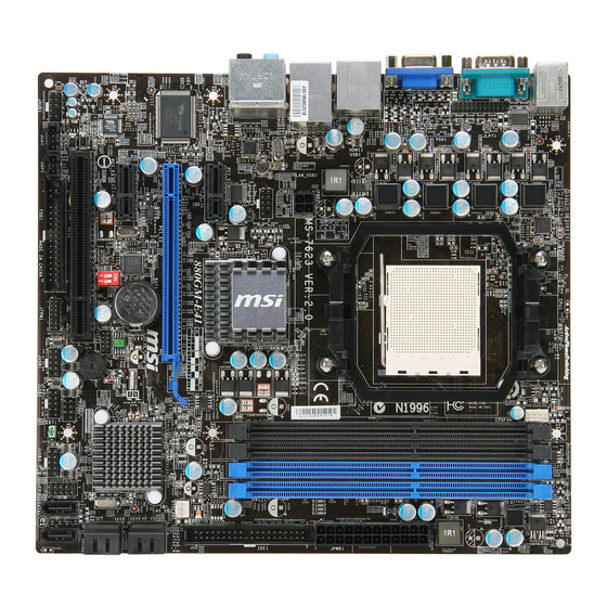
Bottom: USB ports JCOM1 T: Line-In M: Line-Out B: Mic 880G T: RS-Out M: CS-Out B: SS-Out PCI_E1 PCI_E2 SB710 PCI_E3 OC_SW1 PCI1 JFP2 JFP1 JBAT1 JCD1 JTPM1 JUSB1 JUSB2 JUSB3 JAUD1 JSP1 FDD1 880GM-E41 Series (MS-7623 v2.X) Micro-ATX Mainboard... -
Page 15: Packing Checklist
MS-7623 Packing Checklist MSI Driver/Utility DVD MSI mainboard SATA Cable (optional) Standard Cable for USB Bracket (optional) Power Cable (optional) IDE Devices (optional) User’s Guide Back IO Shield * The pictures are for reference only and may vary from the packing contents of the... -
Page 17: Chapter 2 Hardware Setup
Chapter 2 Hardware Setup This chapter provides you with the information about hardware setup procedures. While doing the installa- tion, be careful in holding the components and follow the installation procedures. For some components, if you install in the wrong orientation, the components will not work properly. -
Page 18: Quick Components Guide
Hardware Setup Hardware Setup Quick Components Guide JPWR2, p.2-9 CPU, p.2-4 CPUFAN, p.2-14 DDR3, p.2-7 Back Panel, p.2-10 JPWR1, p.2-9 IDE1, p.2-12 JCOM1, p.2-17 JCI1, p.2-14 SYS_FAN1, p.2-14 PCIE, p.2-20 OC_SW1, p.2-18 SATA1~6, p.2-13 PCI, p.2-20 JAUD1, p.2-15 JCD1, p.2-14 FDD1, p.2-12 JUSB1~3, p.2-15 JFP1, JFP2, p.2-13... -
Page 19: Screw Holes
MS-7623 MS-7623 Screw Holes When you install the mainboard, you have to place the mainboard into the chassis in the correct direction. The locations of screws holes on the mainboard are shown as below. The side has to toward the rear, the position for the I/O shield of the chassis. -
Page 20: Cpu (Central Processing Unit)
When you are installing the CPU, make sure to install the cooler to prevent overheating. If you do not have the CPU cooler, consult your dealer before turning on the computer. For the latest information about CPU, please visit http://www.msi.com/index. php?func=cpuform2... - Page 21 MS-7623 MS-7623 CPU & Cooler Installation When you are installing the CPU, make sure the CPU has a cooler attached on the top to prevent overheating. Meanwhile, do not forget to apply some thermal paste on CPU before installing the heat sink/cooler fan for better heat dispersion. Follow the steps below to install the CPU &...
- Page 22 Hardware Setup Hardware Setup Position the cooling set onto the Then press down the other end of the retention mechanism. clip to fasten the cooling set on the Hook one end of the clip to hook top of the retention mechanism. first.
-
Page 23: Memory
MS-7623 MS-7623 Memory These DIMM slots are used for installing memory modules. For more information on compatible components, please visit http://www.msi.com/index.php?func=testreport DDR3 240-pin, 1.5V 48x2=96 pin 72x2=144 pin Dual-Channel mode Population Rule In Dual-Channel mode, the memory modules can transmit and receive data with two data bus lines simultaneously. -
Page 24: Installing Memory Modules
Hardware Setup Hardware Setup Installing Memory Modules The memory module has only one notch on the center and will only fit in the right orientation. Insert the memory module vertically into the DIMM slot. Then push it in until the golden finger on the memory module is deeply inserted in the DIMM slot. -
Page 25: Power Supply
MS-7623 MS-7623 Power Supply ATX 24-pin Power Connector: JPWR1 This connector allows you to connect an ATX 24-pin power supply. To connect the ATX 24-pin power supply, make sure the plug of the power supply is inserted in the proper orientation and the pins are aligned. -
Page 26: Back Panel
Hardware Setup Hardware Setup Back Panel USB Ports Mouse Line-In RS-Out Line-Out CS-Out SS-Out Keyboard Serial Port VGA Port HDMI Port USB Ports ▶ Mouse/Keyboard The standard PS/2 mouse/keyboard DIN connector is for a PS/2 mouse/keyboard. ® ® ▶ Serial Port The serial port is a 16550A high speed communications port that sends/ receives 16 bytes FIFOs. - Page 27 MS-7623 MS-7623 ▶ Audio Ports These audio connectors are used for audio devices. It is easy to differentiate between audio effects according to the color of audio jacks. ■ Line-In (Blue) - Line In, is used for external CD player, tape-player or other audio devices.
-
Page 28: Connectors
Hardware Setup Hardware Setup Connectors Floppy Disk Drive Connector: FDD1 This connector supports 360KB, 720KB, 1.2MB, 1.44MB or 2.88MB floppy disk drive. * The MB layout in this figure is for reference only. IDE Connector: IDE1 This connector supports IDE hard disk drives, optical disk drives and other IDE de- vices. -
Page 29: Serial Ata Connector Sata1-6
MS-7623 MS-7623 Serial ATA Connector: SATA1~6 This connector is a high-speed Serial ATA interface port. Each connector can connect to one Serial ATA device. * The MB layout in this figure is for reference only. Important • Please do not fold the Serial ATA cable into 90-degree angle. Otherwise, data loss may occur during transmission. - Page 30 Hardware Setup Hardware Setup Fan Power Connectors: CPUFAN, SYSFAN1 The fan power connectors support system cooling fan with +12V. When connecting the wire to the connectors, always note that the red wire is the positive and should be con- nected to the +12V; the black wire is Ground and should be connected to GND. If the mainboard has a System Hardware Monitor chipset on-board, you must use a specially designed fan with speed sensor to take advantage of the CPU fan control.
- Page 31 MS-7623 MS-7623 Front USB Connector: JUSB1/ JUSB2/ JUSB3 This connector, compliant with Intel I/O Connectivity Design Guide, is ideal for con- ® necting high-speed USB interface peripherals such as USB HDD, digital cameras, MP3 players, printers, modems and the like. * The MB layout in this figure is for reference only.
- Page 32 Hardware Setup Hardware Setup S/PDIF-Out Connector: JSP1 This connector is used to connect S/PDIF (Sony & Philips Digital Interconnect Format) interface for digital audio transmission. * The MB layout in this figure is for reference only. S/PDIF-Out Bracket (optional) TPM Module connector: JTPM1 This connector connects to a TPM (Trusted Platform Module) module (optional).
- Page 33 MS-7623 MS-7623 Serial Port Connector: JCOM1 This connector is a 16550A high speed communication port that sends/receives 16 bytes FIFOs. You can attach a serial device. 2-17...
-
Page 34: Switch
Hardware Setup Hardware Setup Switch Overclock FSB Switch: OC_SW1 You can overclock the processor frequency by changing the switch. Follow the instructions below to set the CPU clock. Default Increase 10% Increase 15% Increase 20% speed of CPU speed of CPU speed of CPU clock clock... -
Page 35: Jumpers
MS-7623 MS-7623 Jumpers Clear CMOS Jumper: JBAT1 There is a CMOS RAM onboard that has a power supply from an external battery to keep the data of system configuration. With the CMOS RAM, the system can automati- cally boot OS every time it is turned on. If you want to clear the system configuration, set the jumper to clear data. -
Page 36: Slots
Hardware Setup Hardware Setup Slots PCIE (Peripheral Component Interconnect Express) Slot The PCIE slot supports the PCIE interface expansion card. PCIEx16 Slot PCIEx1 Slot PCI (Peripheral Component Interconnect) Slot The PCI slot supports LAN card, SCSI card, USB card, and other add-on cards that comply with PCI specifications. -
Page 37: Led Status Indicators
MS-7623 MS-7623 LED Status Indicators LED1 APS LED Status Indicator: LED1 These APS (Active Phase Switching) LED indicates the current CPU power phase mode. Follow the instructions below to read. LED1 The LED will light when CPU is in 3 phase power mode. OFF The LED will go off when CPU is in 1 phase power mode. -
Page 39: Chapter 3 Bios Setup
Chapter 3 BIOS Setup This chapter provides information on the BIOS Setup program and allows you to configure the system for op- timum use. You may need to run the Setup program when: ■ An error message appears on the screen during the system booting up, and requests you to run SETUP. -
Page 40: Entering Setup
BIOS Setup BIOS Setup Entering Setup Power on the computer and the system will start POST (Power On Self Test) process. When the message below appears on the screen, press <DEL> key to enter Setup. Press DEL to enter SETUP If the message disappears before you respond and you still wish to enter Setup, restart the system by turning it OFF and On or pressing the RESET button. -
Page 41: Control Keys
MS-7623 MS-7623 Control Keys <↑> Move to the previous item <↓> Move to the next item <←> Move to the item in the left hand <→> Move to the item in the right hand <Enter> Select the item <Esc> Jumps to the Exit menu or returns to the main menu from a submenu <+/PU>... -
Page 42: The Main Menu
BIOS Setup BIOS Setup The Main Menu ▶ Standard CMOS Features Use this menu for basic system configurations, such as time, date etc. ▶ Advanced BIOS Features Use this menu to setup the items of the BIOS special enhanced features. ▶... - Page 43 MS-7623 MS-7623 ▶ M-Flash Use this menu to read/ flash the BIOS from storage drive (FAT/ FAT32 format only). ▶ Overclocking Profile Use this menu to save/ load your settings to/ from CMOS for BIOS. ▶ Load Fail-Safe Defaults Use this menu to load the default values set by the BIOS vendor for stable system performance.
-
Page 44: Standard Cmos Features
BIOS Setup BIOS Setup Standard CMOS Features The items in Standard CMOS Features Menu include some basic setup items. Use the arrow keys to highlight the item and then use the <PgUp> or <PgDn> keys to select the value you want in each item. ▶... - Page 45 MS-7623 MS-7623 ▶ IDE Primary Master/ Slave & SATA1~6 Press <Enter> to enter the sub-menu, and the following screen appears. ▶ Device / Vendor / Size It will show the device information that you connected to the SATA connector. ▶ LBA/Large Mode This allows you to enable or disable the LBA Mode.
- Page 46 BIOS Setup BIOS Setup ▶ System Information Press <Enter> to enter the sub-menu, and the following screen appears. This sub-menu shows the CPU information, BIOS version and memory status of your system (read only).
-
Page 47: Advanced Bios Features
MS-7623 MS-7623 Advanced BIOS Features ▶ Boot Sequence Press <Enter> to enter the sub-menu. ▶ Boot Device These items allow you to arrange the order that the BIOS uses to look for a boot device from which to load the operating system during the boot process. ▶... - Page 48 BIOS Setup BIOS Setup ▶ Full Screen Logo Display This item enables this system to show the company logo on the boot-up screen. Settings are: [Enabled] Shows a still image (logo) on the full screen at boot. [Disabled] Shows the POST messages at boot. ▶...
-
Page 49: Integrated Peripherals
MS-7623 MS-7623 Integrated Peripherals ▶ USB Controller This setting allows you to enable/disable the onboard USB 1.1/ 2.0 controller. ▶ USB Device Legacy Support Select [Enabled] if you need to use a USB-interfaced device in the operating system. ▶ Onboard LAN Controller This setting allows you to enable/disable the onboard LAN controller. - Page 50 BIOS Setup BIOS Setup ▶ OnChip SATA Controller This item allows users to enable or disable the SATA controller. ▶ RAID Mode This item is used to select mode for SATA connectors. ▶ I/O Devices Press <Enter> to enter the sub-menu and the following screen appears: ▶...
-
Page 51: Power Management Setup
MS-7623 MS-7623 Power Management Setup Important S3-related functions described in this section are available only when the BIOS sup- ports S3 sleep mode. ▶ ACPI Function This item is to activate the ACPI (Advanced Configuration and Power Management Interface) Function. If your operating system is ACPI-aware, such as Windows 98SE/ 2000/ ME/ XP, select [Enabled]. - Page 52 BIOS Setup BIOS Setup ▶ Restore On AC Power Loss This item specifies whether your system will reboot after a power failure or interrupt occurs. Settings are: [Off] Always leaves the computer in the power off state. [On] Always leaves the computer in the power on state. [Last State] Restore the system to the status before power failure or interrupt occurred.
-
Page 53: H/W Monitor
MS-7623 MS-7623 H/W Monitor ▶ Chassis Intrusion The field enables or disables the feature of recording the chassis intrusion status and issuing a warning message if the chassis is once opened. To clear the warning mes- sage, set the field to [Reset]. The setting of the field will automatically return to [Enabled] later. -
Page 54: Green Power
BIOS Setup BIOS Setup Green Power ▶ CPU Phase Control When set to [Enabled], the hardware will auto adjust the CPU power phase according to the loading of CPU to reach the best power saving function. ▶ Motherboard LED Control This item is used to control the power phase LEDs of the motherboard. - Page 55 MS-7623 MS-7623 BIOS S ettIng aSSwOrd ▶ U-Key This item is used to enable/ disable USB driver device as a key. ▶ Make U-Key at This item is used to specify the USB driver device as a key. ▶ Change Supervisor Password This item is used to set the supervisor password.
- Page 56 BIOS Setup BIOS Setup Important Type the password, up to eight characters in length, and press <Enter>. The password typed now will replace any previously set password. You will be prompted to confirm the password. Retype the password and press <Enter>. You may also press <Esc> to abort the selection and not enter a password.
-
Page 57: Cell Menu
MS-7623 MS-7623 Cell Menu Important Change these settings only if you are familiar with the chipset. ▶ Current CPU / DRAM / CPU-NB Frequency These items show the current clocks of CPU, Memory and CPU-NB speed. Read-only. ▶ CPU Specifications Press <Enter>... - Page 58 BIOS Setup BIOS Setup ▶ CPU Technology Support Press <Enter> to enter the sub-menu and the following screen appears. This sub- menu shows the technologies that the installed CPU supported. ▶ CPU Feature Press <Enter> to enter the sub-menu and the following screen appears: ▶...
- Page 59 MS-7623 MS-7623 ▶ AMD Cool’n’Quiet The Cool’n’Quiet technology can effectively and dynamically lower CPU speed and power consumption. ▶ C1E Support To enable this item to red the CPU power consumption while idle. Not all porcessors support Enhanced Halt tate (C1E). Important To ensure that Cool’n’Quiet function is activated and will be working properly, it is required to double confirm...
- Page 60 BIOS Setup BIOS Setup ▶ Unlock CPU Core This item allows you to unlock the additional cores, you could set it [Enabled] and then set Advanced Clock Calibration [Auto] in order to be able to activate the processor cores. ▶ Advanced Clock Calibration This item is for overclock.
- Page 61 MS-7623 MS-7623 ▶ Advance DRAM Configuration Press <Enter> to enter the sub-menu and the following screen appears. ▶ DRAM Timing Mode Select whether DRAM timing is controlled by the SPD (Serial Presence Detect) EEPROM on the DRAM module. Setting to [Auto] enables DRAM timings and the following “Advance DRAM Configuration”...
- Page 62 BIOS Setup BIOS Setup ▶ CPU Voltage (V)/ CPU-NB Voltage (V)/ DRAM Voltage (V) These items are used to adjust the voltage of CPU, Memory and chipset. ▶ Spread Spectrum When the mainboard’s clock generator pulses, the extreme values (spikes) of the pulses create EMI (Electromagnetic Interference).
- Page 63 MS-7623 MS-7623 Important Failed Overclocking Resolution This motherboard supports overclocking greatly. However, please make sure your peripherals and components are bearable for some special settings. Any operation that exceeds product specification is not recommended. Any risk or damge resulting from improper operation will not be under our product warranty.
- Page 64 BIOS Setup BIOS Setup laSh == BIOS Update or Boot 2nd BIOS From USB drive== ▶ M-Flash function as M-Flash function allows you to flash BIOS from USB drive/ storage drive (FAT/ FAT32 format only), or allows the system to boot from the BIOS file inside USB drive (FAT/ FAT32 format only).
- Page 65 MS-7623 MS-7623 Important • Please refer to the block diagram below about the M-Flash function. • Due to the special design of some graphics cards will cause dark screen during M- flash operation, and you may refer the beeps from the system to confirm the current M-flash process.
- Page 66 BIOS Setup BIOS Setup ▶ Load BIOS source file from When the M-Flash function as sets to [Boot] or [BIOS Update], this item is selectable. Use this item to select particular BIOS file from the USB/ Storage (FAT/32 format only) drive. == Backup BIOS to USB drive == The following fields are used to read the onboard BIOS ROM data, and save it to USB drive/ storage drive.
- Page 67 MS-7623 MS-7623 verclOckIng rOFIle ▶ Overclocking Profile 1/ 2/ 3/ 4/ 5/ 6 These items are used to save the currect settings to selected profile, and they are also used to load the settings from the selected profile. ▶ OC Retry Count When the overclocking is failed, setting this item to [1, 3, 5] will allow system to reboot 1/ 3/ 5 times with the overclocking configuration.
-
Page 68: Load Fail-Safe/ Optimized Defaults
BIOS Setup Load Fail-Safe/ Optimized Defaults The two options on the main menu allow users to restore all of the BIOS settings to the default Fail-Safe or Optimized values. The Optimized Defaults are the default values set by the mainboard manufacturer specifically for optimal performance of the mainboard. The Fail-Safe Defaults are the default values set by the BIOS vendor for stable system performance. -
Page 69: Appendix Avia Hd Audio
Appendix A VIA HD Audio The VIA HD audio provides 10-channel DAC that simul- taneously supports 7.1 sound playback and 2 channels of independent stereo sound output through the Front- Out-Left and Front-Out-Right channels. -
Page 70: Installing The Via Audio Driver
Realtek Audio Realtek Audio Installing the VIA Audio Driver You need to install the audio driver for VIA audio codec to function properly before you can get access to 2-, 4-, 6-, 8- channel or 7.1+2 channel audio operations. Follow the procedures described below to install the drivers for different operating systems. - Page 71 MS-7623 MS-7623 Click Next and follow the Install Wizard to install the VIA audio driver. Click here After the installation is completed, click Finish to restart the system. Select this option Click here After installing the audio driver, you are able to use the 2-, 4-, 6- or 8- channel audio feature now.
-
Page 72: Software Introduction
Realtek Audio Realtek Audio Software Introduction HD Audio Deck: Adeck Audio Deck (Adeck) is a Windows based program which co-works with the VIA HD Au- dio driver and the VIA HD Audio chip. With the advanced audio control interface, users can make the best use of the VIA Audio chip and create powerful customized sound environments. -
Page 73: Display Mode
MS-7623 MS-7623 Display Mode The VIA Adeck has two basic display modes: “Simple Mode” and “Full Mode”. Simple Mode Once Adeck has been launched, the panel will be displayed in the center of windows desktop. The Adeck system is initialized using the simple mode. In this mode, the user only has limited control and audio information. -
Page 74: Panel Detail
Realtek Audio Realtek Audio Panel Detail Adeck consists of two parts; A top and bottom panel. In the simple mode, only the top panel will be fully shown. In the full mode, both the top and bottom panel will be fully expanded. - Page 75 MS-7623 MS-7623 and Bass Management functions can not be enabled at the same time. Configuration Panels: On the bottom of the top panel, there is a row of buttons. When any of the buttons are activated (except the "Power" button), the bottom panel ex- pands to show the selected panel.
-
Page 76: Configuration Panels
Realtek Audio Realtek Audio Configuration Panels Speaker Configuration Panel As shown below, the Speaker Configuration Panel is divided into two parts. On the left side, the user can select the number of audio channels. There are up to 8 chan- nels available. - Page 77 MS-7623 MS-7623 The headphone volume controls are as shown below. To switch back to the speaker volume controls, click on the speaker icon at the bottom-right corner. Click here to return to speaker control Headphone Volume Headphone Test...
-
Page 78: Mixer Configuration Panel
Realtek Audio Realtek Audio Mixer Configuration Panel On the Mixer Configuration Panel, there are four mixer devices that can be selected: playback, microphone, line in and front microphone. Below shows the Playback Mixer. Each of the Playback items has a volume, balance and mute control. The user can also select the default playback device from a drop-down menu. -
Page 79: Effects Configuration Panel
MS-7623 MS-7623 Effects Configuration Panel There are two sound enhancement controls in Adeck: “Equalizer” and “Bass Manage- ment”. When the Equalizer is selected, the user will see the 10 bands from 31Hz to 16kHz. The equalizer settings will only take effect after the user enables it by press- ing the “On/Off”... - Page 80 Realtek Audio Realtek Audio Below shows the “Bass Management” features. The user can enable the “Bass Man- agement” features by clicking on the “On/Off” button at the top of the “Bass Manage- ment” controls. The “Bass Management” feature allows the user to control the low fre- quency limits for the speakers.
-
Page 81: Jack Configuration Panel
MS-7623 MS-7623 Jack Configuration Panel The Jack Configuration Controls enable the user to configure all the audio jacks on the computer system. The “Back Panel” lists all the jacks at the rear side of the computer system. The “Front Panel” lists all the jacks at the front side of the computer system. In general, the multi-channel playback and recording jacks will be listed in the “Back Panel”... - Page 82 Realtek Audio Realtek Audio The Headphone Configuration Panel is shown below. There are two headphone con- figurations that can be chosen: “Independent Headphone” or “Redirected Headphone”. The “Independent Headphone” feature enables the user to play separate music on the headphone and speaker. For example, the user can use a multi-channel device (such as 5.1 surround sound) to watch a movie while simultaneously using the independent headphone feature to make phone calls through a VoIP Internet phone.
- Page 83 MS-7623 MS-7623 S/PDIF Configuration Panel The S/PDIF Configuration Panel enables the user to configure S/PDIF related control. The “S/PDIF Out” panel allows the user to enable S/PDIF output support and select the S/PDIF output sampling rate. Please note that some S/PDIF decoders do not support 176.4 and 192kHz.
-
Page 84: System Information Panel
Realtek Audio Realtek Audio System Information Panel The System Information Panel displays the current system information. System Information The “Hot Key” Configuration Panel allows the user to set hot keys for controlling the volume and muting. To use the hot keys, “Enable Hot Key Function” must first be checked. - Page 85 MS-7623 MS-7623 When a hot key is pressed, the screen will show a green volume control bar at the bot- tom of the screen and a mute/un-mute icon at the top-right corner of the screen. The on-screen display can be hidden by pressing the “Show/Hide” hot key. A-17...
-
Page 86: Hardware Default Setting
Realtek Audio Realtek Audio Hardware Default Setting The following diagrams are audio back panel default setting. ■ Backpanel audio jacks to 2-channel speakers diagram F r o ■ Backpanel audio jacks to 4-channel speakers diagram F r o R e a A-18... - Page 87 MS-7623 MS-7623 ■ Backpanel audio jacks to 6-channel speakers diagram F r o C e n R e a t e r & S u b w o o f ■ Backpanel audio jacks to 8-channel speakers diagram F r o C e n R e a t e r...
-
Page 89: Appendix Bamd Raid
Appendix B AMD RAID The integrate one SATA host controller separately, and support RAID function for performance and reliability. SB710 SATA RAID (SATA1~6) provides support for RAID 0 (Striping), RAID 1 (Mirroring) & RAID 10 (Striping & Mirroring). RAID 0 greatly improves hard disk I/O per- formance by concurrently striping data across multiple drives. -
Page 90: Raid Configuration
AMD RAID AMD RAID RAID Configuration Creating and deleting RAID set and performing other RAID setting up operations are done in the RAID BIOS. During bootup, a screen similar to the one below will appear for about few seconds. Press <Ctrl-F> to enter FastBuild utility. Important Be sure to enable the RAID function for SATA device in BIOS before configuring the Fastbuild Utility. - Page 91 MS-7623 MS-7623 View Drives Assignments This window displays the model number, capacities and assignment of the drives physi- cally attached to the SATA host adapter.
- Page 92 AMD RAID AMD RAID Define LD (Creating RAID) The selection of the RAID configuration should be based upon factors including perfor- mance, data security, and the number of drives available. It is best to carefully consider the long-term role of the system and plan the data storage strategy. RAID sets can be created either automatically, or to allow the greatest flexibility, manually.
- Page 93 MS-7623 MS-7623 ■ Initialize logical drive, zero the disk drives. RAID 1 or 10 only. ■ Stripe Block Size, the default 64KB is best for most applications. RAID 0 or 10 only. ■ Gigabyte Boundary, allows use of slightly smaller replacement drives. ■...
- Page 94 AMD RAID AMD RAID The LD creation is done, the screen shows the LD information as below.Press ESC key to the main screen. Press ESC key to exit the utility, a message “System is going to REBOOT! Are You Sure?” will display, answer “Y” to exit it and the system will reboot.
- Page 95 MS-7623 MS-7623 Delete LD (Deleting RAID) Select “Delete LD” on the main screen. Choose a LD No you want to delete and press “Del” or “Alt+D” delete the RAID set. On the next screen, a message will display to inform you, press “Ctrl+Y” to delete the RAID set or other key to abort it.
-
Page 96: Installing The Raid Driver (For Bootable Raid Array)
Note: for Windows Vista, you can copy the files to a medium (floppy/ CD/ DVD or USB) Important Please follow the instruction below to make a SATA RAID driver for yourself. Insert the MSI DVD into the DVD-ROM drive. • Click the “Browse CD” on the Setup screen. •... - Page 97 Installing the RAID Driver Under Windows (for Non-bootable RAID Array) Insert the MSI DVD into the DVD-ROM drive. The DVD will auto-run and the setup screen will appear. Under the Driver tab, click on AMD chipset drivers by your need. The AMD chipset drivers includes RAID Driver.
Need help?
Do you have a question about the 880GM-E41 series and is the answer not in the manual?
Questions and answers