Table of Contents
Advertisement
Available languages
Available languages
Advertisement
Table of Contents

Subscribe to Our Youtube Channel
Related Manuals for MSI 880G-E45 Series


Summary of Contents for MSI 880G-E45 Series
- Page 1 880G-E45 series MS-7576 (v1.x) Mainboard G52-75761XD...
-
Page 2: Trademarks
Alternatively, please try the following help resources for further guidance. ◙ Visit the MSI website for FAQ, technical guide, BIOS updates, driver updates, and other information: http://www.msi.com/index.php?func=service ◙ Contact our technical staff at: http://ocss.msi.com... -
Page 3: Safety Instructions
MS-7576 MS-7576 Safety Instructions ■ Always read the safety instructions carefully. ■ Keep this User’s Manual for future reference. ■ Keep this equipment away from humidity. ■ Lay this equipment on a reliable flat surface before setting it up. ■ The openings on the enclosure are for air convection hence protects the equipment from overheating. -
Page 4: Fcc-B Radio Frequency Interference Statement
Preface Preface FCC-B Radio Frequency Interference Statement This equipment has been tested and found to comply with the limits for a Class B digi- tal device, pursuant to Part 15 of the FCC Rules. These limits are designed to provide reasonable protection against harmful inter- ference in a residential installation. -
Page 5: Weee (Waste Electrical And Electronic Equipment) Statement
MSI will comply with the product take back requirements at the end of life of MSI-branded prod- ucts that are sold into the EU. - Page 6 MSI će poštovati zahtev o preuzimanju ovakvih proizvoda kojima je istekao vek trajanja, koji imaju MSI oznaku i koji su prodati u EU. Ove proiz- vode možete vratiti na lokalnim mestima za prikupljanje.
- Page 7 MSI si adeguerà a tale Direttiva ritirando tutti i prodotti marchiati MSI che sono stati venduti all’interno dell’Unione Europea alla fine del loro...
-
Page 8: Table Of Contents
Preface Preface Contents Copyright Notice .................... ii Trademarks ....................ii Revision History..................... ii Technical Support..................ii Safety Instructions ..................iii FCC-B Radio Frequency Interference Statement.......... iv WEEE (Waste Electrical and Electronic Equipment) Statement ....v English ...................... En-1 Mainboard Specifications ...................En-2 Quick Components Guide ..................En-4 Screw Holes .......................En-5 CPU (Central Processing Unit) ................En-6... - Page 9 MS-7576 MS-7576 Français ..................... Fr-1 Spécification ......................Fr-2 Guide Rapide Des Composants ................Fr-4 Trous Taraudés ....................Fr-5 Processeur : CPU ....................Fr-6 Mémoire ......................Fr-9 Connecteurs d’Alimentation ................Fr-11 Panneau arrière ....................Fr-12 Connecteurs ......................Fr-14 Boutons ......................Fr-20 Interrupteur ......................Fr-21 Emplacements ....................Fr-22 Indicateurs De Statut LED .................Fr-25 Réglage BIOS ....................Fr-26 Information De Logiciel ..................Fr-38 Русский...
-
Page 11: English
English 880G-E45 Series Europe version... -
Page 12: Mainboard Specifications
Mainboard Specifications Processor Support ■ Phenom™ II X4/ X3 and Athlon X4/ X3/ X2 processors in the AM3 package. ® (For the latest information about CPU, please visit http://www.msi.com/index.php?func=cpuform2) HyperTransport ■ HyperTransport™ 3.0, supports up to 5.2 GT/s Chipset ■... - Page 13 ■ ATX (30.5cm X 24.4 cm) Mounting ■ 9 mounting holes * If you need to purchase accessories and request the part numbers, you could search the product web page and find details on our web address below http://www.msi.com/index.php En-3...
-
Page 14: Quick Components Guide
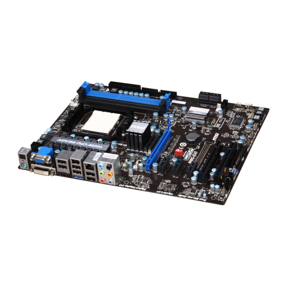
MS-7576 Mainboard Quick Components Guide CPUFAN1, En-16 CPU, En-6 PWR1, En-11 DDR3, En-9 JPWR1, En-11 Back Panel, En-12 IDE1, En-14 SYSFAN1/2, EZ OC Switch, En-21 En-16 SYSFAN3, En-16 SATA1~5, En-15 PCIE, En-22 JFP1, JFP2, En-17 PCI, En-24 JTPM1, En-19 JCOM1, En-19 RESET JCI1, En-15 CMOS... -
Page 15: Screw Holes
Screw Holes When you install the mainboard, you have to place the mainboard into the chassis in the correct direction. The locations of screws holes on the mainboard are shown as below. The side has to to- ward the rear, the position for the I/O shield of the chas- sis. -
Page 16: Cpu (Central Processing Unit
When you are installing the CPU, make sure to install the cooler to prevent overheating. If you do not have the CPU cooler, consult your dealer before turning on the computer. For the latest information about CPU, please visit http://www.msi.com/index. php?func=cpuform2... - Page 17 CPU & Cooler Installation When you are installing the CPU, make sure the CPU has a cooler attached on the top to prevent overheating. Meanwhile, do not forget to apply some thermal paste on CPU before installing the heat sink/cooler fan for better heat dispersion. Follow the steps below to install the CPU &...
- Page 18 MS-7576 Mainboard Position the cooling set onto the re- Then press down the other end of the tention mechanism. clip to fasten the cooling set on the Hook one end of the clip to hook top of the retention mechanism. first.
-
Page 19: Memory
Memory These DIMM slots are used for installing memory modules. For more information on compatible components, please visit http://www.msi.com/index.php?func=testreport DDR3 240-pin, 1.5V 72x2=144 pin 48x2=96 pin Dual-Channel mode Population Rule In Dual-Channel mode, the memory modules can transmit and receive data with two data bus lines simultaneously. - Page 20 MS-7576 Mainboard Installing Memory Modules The memory module has only one notch on the center and will only fit in the right orientation. Insert the memory module vertically into the DIMM slot. Then push it in until the golden finger on the memory module is deeply inserted in the DIMM slot. The plastic clip at each side of the DIMM slot will automatically close when the memory module is properly seated.
-
Page 21: Power Supply
Power Supply ATX 24-pin Power Connector: JPWR1 This connector allows you to connect an ATX 24-pin power supply. To connect the ATX 24-pin power supply, make sure the plug of the power supply is inserted in the proper orientation and the pins are aligned. Then push down the power supply firmly into the connector. -
Page 22: Back Panel
MS-7576 Mainboard Back Panel (optional) 1394 Port Optical S/PDIF-out VGA Port USB Port Line-In RS-Out USB Port Line-Out CS-Out USB Port SS-Out E-SATA Port USB Port Mouse/ HDMI Port DVI-D Port Keyboard ▶ Mouse/Keyboard The standard PS/2 mouse/keyboard DIN connector is for a PS/2 mouse/keyboard. - Page 23 ▶ The standard RJ-45 LAN jack is for connection to Yellow Green/ Orange the Local Area Network (LAN). You can connect a network cable to it. Color LED State Condition Left Yellow LAN link is not established. On(Steady state) LAN link is established. On(brighter &...
-
Page 24: Connectors
MS-7576 Mainboard Connectors Floppy Disk Drive Connector: FDD1 This connector supports 360KB, 720KB, 1.2MB, 1.44MB or 2.88MB floppy disk drive. * The MB layout in this figure is for reference only. IDE Connector: IDE1 This connector supports IDE hard disk drives, optical disk drives and other IDE devices. - Page 25 Serial ATA Connector: SATA1~5 This connector is a high-speed Serial ATA interface port. Each connector can connect to one Serial ATA device. * The MB layout in this figure is for reference only. Important Please do not fold the Serial ATA cable into 90-degree angle. Otherwise, data loss may occur during transmission.
- Page 26 MS-7576 Mainboard Fan Power Connectors: CPUFAN1, SYSFAN1~3 The fan power connectors support system cooling fan with +12V. When connecting the wire to the connectors, always note that the red wire is the positive and should be con- nected to the +12V; the black wire is Ground and should be connected to GND. If the mainboard has a System Hardware Monitor chipset on-board, you must use a specially designed fan with speed sensor to take advantage of the CPU fan control.
- Page 27 Front Panel Connector: JFP1, JFP2 This connector is for electrical connection to the front panel switches and LEDs. The JFP1 is compliant with Intel Front Panel I/O Connectivity Design Guide. ® JFP2 JFP1 IEEE1394 Connector: J1394_1 (Optional) This connector allows you to connect the IEEE1394 device via an optional IEEE1394 bracket.
- Page 28 MS-7576 Mainboard Front USB Connector: JUSB1 / JUSB2 / JUSB3 This connector, compliant with Intel I/O Connectivity Design Guide, is ideal for con- ® necting high-speed USB interface peripherals such as USB HDD, digital cameras, MP3 players, printers, modems and the like. * The MB layout in this figure is for reference only.
- Page 29 Serial Port Connector: JCOM1 This connector is a 16550A high speed communication port that sends/ receives 16 bytes FIFOs. You can attach a serial device. TPM Module connector: JTPM1 This connector connects to a TPM (Trusted Platform Module) module (optional). Please refer to the TPM security platform manual for more details and usages.
-
Page 30: Button
MS-7576 Mainboard Button The motherboard provides the following button for you to set the computer’s function. This section will explain how to change your motherboard’s function through the use of button. Clear CMOS Button: CLR_CMOS1 There is a CMOS RAM on board that has a power supply from external battery to keep the system configuration data. -
Page 31: Switch
Switch Overclock FSB Switch: EZ OC Switch You can overclock the FSB to increase the processor frequency by changing the switch. Follow the instructions below to set the FSB. Default Increase 10% Increase 15% Increase 20% speed of FSB speed of FSB speed of FSB Important •... -
Page 32: Slots
MS-7576 Mainboard Slots PCI (Peripheral Component Interconnect) Express Slot The PCI Express slot supports the PCI Express interface expansion card. PCI Express x16 Slot PCI Express x1 Slot Hybrid CrossFireX™ Technology Hybrid CrossFireX™ technology brings multi-GPU performance capabilities by enabling an AMD 880G integrated graphics processor and a discrete graphics processor to op- ®... - Page 33 Select the Advanced View from the view drop menu. From the “Graphics Settings” tree in the Catalyst Control Center, click Cross- Fire™. From the “Graphics Adapter” list, select the graphics card that acts as the Display GPU. Select “Enable CrossFire™”. Click Apply.
- Page 34 MS-7576 Mainboard PCI (Peripheral Component Interconnect) Slot The PCI slot supports LAN card, SCSI card, USB card, and other add-on cards that comply with PCI specifications. 32-bit PCI Slot Important When adding or removing expansion cards, make sure that you unplug the power sup- ply first.
-
Page 35: Led Status Indicators
LED Status Indicators APS LEDs NB Phase LED RESET CMOS APS LEDs These APS (Active Phase Switching) LEDs indicate the current CPU power phase mode. Follow the instructions below to read. : ON, : OFF 4 of the LEDs will light blue when CPU is in 4 phase power mode. 3 of the LEDs will light blue when CPU is in 3 phase power mode. -
Page 36: Bios Setup
MS-7576 Mainboard BIOS Setup This chapter provides basic information on the BIOS Setup program and allows you to configure the system for optimum use. You may need to run the Setup program when: ■ An error message appears on the screen during the system booting up, and requests you to run BIOS SETUP. - Page 37 Entering Setup Power on the computer and the system will start POST (Power On Self Test) process. When the message below appears on the screen, press <DEL> key to enter Setup. Press DEL to enter SETUP If the message disappears before you respond and you still wish to enter Setup, restart the system by turning it OFF and On or pressing the RESET button.
- Page 38 MS-7576 Mainboard The Main Menu Once you enter BIOS CMOS Setup Utility, the Main Menu will appear on the screen. The Main Menu allows you to select from the setup functions and two exit choices. Use arrow keys to select among the items and press <Enter> to accept or enter the sub-menu.
- Page 39 ▶ User Settings Use this menu to save/ load your settings to/ from CMOS for BIOS. ▶ M-Flash Use this menu to read/ flash the BIOS from storage drive (FAT/ FAT32 format only). ▶ Load Fail-Safe Defaults Use this menu to load the default values set by the BIOS vendor for stable system performance.
- Page 40 Select [Ok] and press Enter to save the configurations and exit BIOS Setup utility. Important The configuration above are for general use only. If you need the detailed settings of BIOS, please see the complete version of English manual on MSI website. En-30...
- Page 41 Cell Menu Introduction : This menu is for advanced user who want to overclock the mainboard. Important Change these settings only if you are familiar with the chipset. ▶ Current CPU / DRAM Frequency These items show the current clocks of CPU and Memory speed. Read-only. ▶...
- Page 42 MS-7576 Mainboard power consumption. Important To ensure that Cool’n’Quiet function is activated and will be working properly, it is required to double confirm that: Run BIOS Setup, and select Cell Menu. Under Cell Menu, find AMD Cool’n’Quiet, • and set this item to “Enabled”. •...
- Page 43 ▶ DIMM1~4 Memory SPD Information Press <Enter> to enter the sub-menu. This sub-menu displays the information of installed memory. ▶ Advance DRAM Configuration Press <Enter> to enter the sub-menu. ▶ DRAM Timing Mode This field has the capacity to automatically detect all of the DRAM timing. If you set this field to [DCT 0], [DCT 1] or [Both], some fields will appear and selectable.
- Page 44 MS-7576 Mainboard ▶ tRRD When the DRAM Timing Mode sets to [DCT 0], [DCT1] or [Both], the field is adjust- able. Specifies the active-to-active delay of different banks. ▶ tWTR When the DRAM Timing Mode sets to [DCT 0], [DCT1] or [Both], the field is adjust- able.
- Page 45 ▶ 1T/2T Memory Timing When the DRAM Timing Mode sets to [DCT 0], [DCT1] or [Both], the field is adjust- able. This field controls the SDRAM command rate. Selecting [1T] makes SDRAM signal controller to run at 1T (T=clock cycles) rate. Selecting [2T] makes SDRAM signal controller run at 2T rate.
- Page 46 MS-7576 Mainboard ▶ CPU VDD Voltage (V)/ CPU-NB VDD Voltage (V)/ CPU Voltage (V)/ CPU-NB Voltage (V)/ DRAM Voltage (V)/ NB Voltage (V)/ HT Link Voltage (V)/ SB Voltage (V) These items are used to adjust the voltage of CPU, Memory and chipset. ▶...
- Page 47 Important Failed Overclocking Resolution This mainboard supports overclocking greatly. However, please make sure your peripherals and components are bearable for some special settings. Any operation that exceeds product specification is not recommended. Any risk or damge resulting from improper operation will not be under our product warranty. Two ways to save your system from failed overclocking...
-
Page 48: Software Information
Driver menu : The Driver menu shows the available drivers. Install the driver by your desire and to activate the device. Utility menu : The Utility menu shows the software applications that the mainboard supports. Important Please visit the MSI website to get the latest drivers and BIOS for better system performance. En-38... -
Page 49: Deutsch
Deutsch 880G-E45 Serie Europe version... -
Page 50: Spezifikationen
MS-7576 Mainboard Spezifikationen Prozessoren ■ Phenom™ II X4/ X3 and Athlon X4/ X3/ X2 Prozessoren für Sockel AM3. ® (Weitere CPU Informationen finden Sie unter http://www.msi.com/index.php?func=cpuform2) HyperTransport ■ HyperTransport™ 3.0, unterstützt bis zu 5,2 GT/s Chipsatz ■ North-Bridge: AMD 880G Chipsatz ®... - Page 51 3 PCI Express x1-Steckplätze 2 PCI-Steckplätze, unterstützen 3,3V/ 5V PCI Bus Interface Form Faktor ■ ATX (30,5cm X 24,4 cm) Montage ■ 9 Montagebohrungen * Wenn Sie für Bestellungen von Zubehör Teilenummern benötigen, finden Sie diese auf unserer Produktseite unter http://www.msi.com/index.php De-3...
-
Page 52: Komponenten-Übersicht
MS-7576 Mainboard Komponenten-Übersicht CPUFAN1, De-16 CPU, De-6 PWR1, De-11 DDR3, De-9 JPWR1, De-11 Rücktafel, De-12 IDE1, De-14 SYSFAN1/2, EZ OC Schalter, De-21 De-16 SYSFAN3, De-16 SATA1~5, De-15 PCIE, De-22 JFP1, JFP2, De-17 PCI, De-24 JTPM1, De-19 JCOM1, De-19 RESET JCI1, De-15 CMOS FDD1, De-14 JUSB1~3, De-18... -
Page 53: Schraubenlöcher
Schraubenlöcher Wenn Sie das Mainboard zu installieren, müssen Sie das Mainboard in das Chassis in der korrekten Richtung setzen. Die Standorte von Schraubenlöchern auf dem Main- board sind wie nachfolgend gezeigt. Seite muss nach hinten, die Position für E/A-Abschirmung des Chassis. RESET CMOS Schraubenlöcher... -
Page 54: Cpu (Prozessor
Überhitzung zu vermeiden. Verfügen Sie über keinen Kühler, setzen Sie sich bitte mit Ihrem Händler in Verbindung, um einen solchen zu erwerben und zu installieren. Um die neuesten Informationen zu unterstützten Prozessoren zu erhalten, besuchen Sie bitte http://www.msi.com/index.php?func=cpuform2 Wichtig Überhitzung Überhitzung beschädigt die CPU und das System nachhaltig. - Page 55 CPU & Kühler Einbau Wenn Sie die CPU einbauen, stellen Sie bitte sicher, dass Sie auf der CPU einen Kühler anbringen, um Überhitzung zu vermeiden. Vergessen Sie nicht, etwas Siliziumwärmel- eitpaste auf die CPU aufzutragen, bevor Sie den Prozessorkühler installieren, um eine Ableitung der Hitze zu erzielen.
- Page 56 MS-7576 Mainboard Setzen Sie den Kühler auf die Küh- Dann drücken Sie das andere Ende lerhalterung und hacken Sie zuerst des Bügels herunter, um den Kühler ein Ende des Kühlers an dem Modul auf der Kühlerhalterung zu fixieren . fest. Anschließend ziehen Sie den Sicher- ungshebel an der Seite fest.
-
Page 57: Speicher
Speicher Diese DIMM-Steckplätze nehmen Arbeitsspeichermodule auf. Die neusten Infor- mationen über kompatible Bauteile finden Sie unter http://www.msi.com/index. php?func=testreport DDR3 240-polig, 1,5V 72x2=144 Pole 48x2=96 Pole Dual-Channel mode Population Rule Populationsregeln für Dual-Kanal-Speicher Im Dual-Kanal-Modus können Arbeitsspeichermodule Daten über zwei Datenbusleitun- gen gleichzeitig senden und empfangen. - Page 58 MS-7576 Mainboard Vorgehensweise beim Einbau von Speicher Modulen Die Speichermodulen haben nur eine Kerbe in der Mitte des Moduls. Sie passen nur in einer Richtung in den Sockel. Stecken Sie das Arbeitsspeichermodul senkrecht in den DIMM-Steckplatz ein. Drücken Sie anschließnd das Arbeitsspeichermodul nach unten, bis die Kontakt- seite richtig tief in dem DIMM-Steckplatz sitzt.
-
Page 59: Stromversorgung
Stromversorgung ATX 24-poliger Stromanschluss: JPWR1 Mit diesem Anschluss verbinden Sie den ATX 24-poligen Anschluss des Netzteils. Achten Sie bei dem Verbinden des ATX 24-poligen Stromanschlusses darauf, dass der Anschluss des Netzteils richtig auf den Anschluss an der Hauptplatine ausgerichtet ist. Drücken Sie dann den Anschluss des Netzteils fest nach unten, um eine richtige Verbindung zu gewährleisten. -
Page 60: Rücktafel
MS-7576 Mainboard Rücktafel (optional) 1394 Anschluss optischer S/PDIF- VGA Anschluss Anschluss Ausgang Line-In RS-Out USB Anschluss Line-Out CS-Out USB Anschluss SS-Out E-SATA USB Anschluss Maus/ HDMI Anschluss DVI-D Anschluss Anschluss Tastatur ▶ Maus/Tastatur Die Standard PS/2 Maus/Tastatur Stecker Mini DIN ist für eine PS/2 Maus/Tastatur. - Page 61 ▶ Die Standard RJ-45 Buchse ist für Anschlus zum Gelb Grün/ Orange an ein Lokales Netzwerk (Local Area Network - LAN). Hier kann ein Netzwerkkabel angeschlossen werden. Farbe LED Status Zustand Links Gelb Keine Verbindung mit dem LAN. An (Dauerleuchten) Verbindung mit dem LAN.
-
Page 62: Anschlüssen
MS-7576 Mainboard Anschlüssen Anschluss des Diskettenlaufwerks: FDD1 An diesem Anschluss unterstützt ein Diskettenlaufwerke mit 360KB, 720KB, 1,2MB, 1,44MB oder 2,88MB Kapazität. * Das MB-Layout in dieser Abbildung haben nur Orientierungscharakter. IDE Anschluss: IDE1 An diesem Anschluss können IDE Festplatten, optische Laufwerke und andere Geräte betrieben werden. - Page 63 Serial ATA Anschluss: SATA1~5 Der Anschluss ist eine Hochgeschwindigkeitsschnittstelle der Serial ATA. Pro An- schluss kann ein S-ATA Gerät angeschlossen werden. * Das MB-Layout in dieser Abbildung haben nur Orientierungscharakter. Wichtig Bitte falten Sie das Serial ATA Kabel nicht in einem Winkel von 90 Grad, da dies zu Datenverlusten während der Datenübertragung führt.
- Page 64 MS-7576 Mainboard Stromanschlüsse für Lüfter: CPUFAN1, SYSFAN1~3 Die Anschlüsse unterstützen aktive Systemlüfter mit + 12V. Wenn Sie den Anschluss herstellen, sollten Sie immer darauf achten, dass der rote Draht der positive Pol ist, und mit +12V verbunden werden sollte. Der schwarze Draht ist der Erdkontakt und sollte mit GND verbunden werden.
- Page 65 Front Panel Connector: JFP1, JFP2 Diese Anschlüsse sind für das Frontpanel. Sie dienen zum Anschluss der Schalter und LEDs des Frontpanels. JFP1 erfüllt die Anforderungen des “Intel Front Panel I/O Con- ® nectivity Design Guide”. JFP2 JFP1 IEEE1394-Anschluss: J1394_1 (Optional) Dieser Anschluss erlaubt Ihren,die Vorrichtung IEEE1394 über ein externes IEEE1394 Slotblech anzuschließen.
- Page 66 MS-7576 Mainboard USB Vorderanschluss: JUSB1 / JUSB2 / JUSB3 Dieser Anschluss entspricht den Richtlinien des Intel I/O Connectivity Design Guide. ® Er ist bestens geeignet, Hochgeschwindigkeits- USB- Peripheriegeräte anzuschließen, wie z.B. USB Festplattenlaufwerke, Digitalkameras, MP3-Player, Drucker, Modems und ähnliches. * Das MB-Layout in dieser Abbildung haben nur Orientierungscharakter. USB Slotblech (optional) Wichtig Bitte beachten Sie, dass Sie die mit VCC (Stromführende Leitung) und GND (Erdlei-...
- Page 67 Serieller Anschluss: JCOM1 Es handelt sich um eine 16550A Kommunikationsschnittstelle, die 16 Bytes FIFOs sendet/empfängt. Hier lässt sich eine serielle Maus oder andere serielle Geräte direkt anschließen. TPM Modul Anschluss: JTPM1 Dieser Anschluss wird für das optionale TPM Modul (Trusted Platform Module) ver- wendt.
-
Page 68: Tasten
MS-7576 Mainboard Tasten Das Motherboard unterstützt die folgende Tasten, um die Funktion des Computers einzustellen. Dieser Abschnitt beschreibt, wie man die Funktionen des Motherboards durch den Gebrauch der Taste ändert. CMOS leeren-Taste: CLR_CMOS1 Auf der Hauptplatine befindet sich ein CMOS RAM, das von einer zusätzlichen Bat- terie mit Strom versorgt wird, um die Systemkonfigurationsdaten zu behalten. -
Page 69: Schalter
Schalter Übertaktung durch FSB Schalter: EZ OC Switch Mit der Änderung der Schalter kann der FSB-Takt erhöht werden. Folgen Sie den An- weisungen, um FSB einzustellen. Standardwerte Erhöhen der FSB- Erhöhen der FSB- Erhöhen der FSB- Geschwindigkeit Geschwindigkeit Geschwindigkeit um 10% um 15% um 20% Wichtig... -
Page 70: Steckplätze
MS-7576 Mainboard Steckplätze PCI (Peripheral Component Interconnect Express) Sterckplatz Der PCI Express-Steckplatz unterstützt eine Erweiterungskarte mit der PCI Express- Schnittstelle. PCI Express x16 Steckplatz PCI Express x1 Steckplatz Hybrid CrossFireX™ Technologie Die Hybrid CrossFireX™ Technologie bietet Multi-GPU Leistung, mit AMD 880G inte- ®... - Page 71 Wählen Sie erweiterte Ansicht vom Ansichtaufklappmenü aus. In den Grafik-Einstellungen auf dem Catalyst Control Center, klicken Sie Cross- Fire™. In der Grafikadapter-Liste wählen Sie die Grafikkarte aus, die als Anzeige der GPU dient. Hier wählen Sie die Option “Enable CrossFire ”...
- Page 72 MS-7576 Mainboard PCI (Peripheral Component Interconnect) Steckplatz Der PCI-Steckplatz kann LAN-Karten, SCSI-Karten, USB-Karten und sonstige Zusatz- karten aufnehmen, die mit den PCI-Spezifikationen konform sind. 32-Bit PCI Steckplatz Wichtig Achten Sie darauf, dass Sie zuerst das Netzkabel aus der Steckdose herausziehen, bevor Sie eine Erweiterungskarte installieren oder entfernen.
-
Page 73: Led Statusdikatoren
LED Statusdikatoren APS LEDs NB Phase LED RESET CMOS APS LEDs Diese APS (Active Phase Switching) LEDs zeigen den gegenwärtigen CPU Strrompha- se Modus an. Lesen Sie die folgenden Anweisungen. : EIN, : AUS 4 der LED leuchten hellblau, wenn CPU in der Phase 4 des Power-Modus 3 der LED leuchten hellblau, wenn CPU in der Phase 3 des Power-Modus 2 der LED leuchten hellblau, wenn CPU in der Phase 2 des Power-Modus 1 der LED leuchtet hellblau, wenn CPU in der Phase 2 des Power-Modus... -
Page 74: Bios Setup
MS-7576 Mainboard BIOS Setup Dieses Kapitel enthält Informationen über das BIOS Setup und ermöglicht es Ihnen, Ihr System optimal auf Ihre Anforderungen einzustellen. Notwendigkeit zum Aufruf des BIOS besteht, wenn: ■ Während des Bootvorgangs des Systems eine Fehlermeldung erscheint und Sie zum Aufruf des BIOS SETUP aufgefordert werden. - Page 75 Aufruf des BIOS Setups Nach dem Einschalten beginnt der Computer den POST (Power On Self Test -Selb- stüberprüfung nach Anschalten). Sobald die Meldung unten erscheint, drücken Sie die Taste <Entf>(<Del>) um das Setup aufzurufen. Press DEL to enter SETUP (ENTF drücken, um das Einstellungsprogramm zu öffnen) Wenn die Nachricht verschwindet, bevor Sie reagieren und Sie möchten immer noch ins Setup, starten Sie das System neu, indem Sie es erst AUS- und danach wieder ANSCHALTEN, oder die “RESET”-Taste am Gehäuse betätigen.
- Page 76 MS-7576 Mainboard Das Hauptmenü Nachdem Sie das BIOS CMOS Setup Utility, aufgerufen haben, erscheint das Haupt- menü. Es weist zehn Setup- Funktionen und zwei Arten das Menü zu verlassen auf. Verwenden Sie die Pfeiltasten, um im Menü zu navigieren und drücken Sie die Eing- abetaste (<Enter>), um ein Untermenü...
- Page 77 ▶ User Settings Abspeichern/ laden die Einstellungen im/ vom CMOS für BIOS. ▶ M-Flash In diesem Menü können Sie das BIOS vom Speicher-Antrieb abtasten/ aufblinken (nur FAT/ FAT32 Format). ▶ Load Fail-Safe Defaults In diesem Menü können Sie eine stabile, werkseitig gespeicherte Einstellung des BIOS Speichers laden.
- Page 78 Drücken Sie auf [OK] und <Enter>, um die (neuen) Einstellungen zu speichern und das BIOS Setup zu verlassen. Wichtig Die Konfiguration oben dienen nur generellen Zwecken. Wenn Sie detaillierte BIOS- Einstellungen benötigen, dann sehen Sie bitte das Handbuch in Englischer Sprache auf der MSI Website ein. De-30...
- Page 79 Cell Menu Introduction: Das Menü ist für den weiteren Benutzer, der die Haupt- platine übertakten mögen. Wichtig Nur wenn Sie mit dem Chipsatz vertraut sind, können Sie die Einstellung ändern. ▶ Current CPU / DRAM Frequency Zeigt die derzeitige Frequenz der CPU/ des Speichers & die Geschwindigkeit des CPU- NBs.
- Page 80 MS-7576 Mainboard ▶ AMD Cool’n’Quiet Die Cool’n’Quiet-Technologie kann die CPU-Geschwindigkeit und den Stromverbrauch effizient und dynamisch herabsetzen. Wichtig Für eine einwandfreie Funktion von Cool’n’Quiet muss folgende Vorgehensweise un- bedingt sichergestellt werden: • BIOS Setup ausführen und wählen Cell Menu aus Unter Cell Menu setzen Sie AMD Cool’n’Quiet, auf “Enabled”.
- Page 81 Mode 1 Geringfugige OC während POST und dann wenden volles OC an, wenn Sie OS laden Mode 2 Laden Sie das OS, dann wenden Sie die OC Einstellungen an. ▶ Memory-Z Drücken Sie die Eingabetaste <Enter>, um das Untermenü aufzurufen. ▶...
- Page 82 MS-7576 Mainboard ▶ Lautet die Einstellung unter DRAM Timing Mode [DCT 0], [DCT1] oder [Both], kön- nen Sie hier die DRAM Timing angeben. Die Reihe Taktzyklen Option spezifiziert die Mindestdauer der Taktgeberzyklen. Die Speicherreihe einen vollen Zyklus Zeit braucht, von der Reihe Aktivierung bis zu Precharge der aktiven Reihe fest. ▶...
- Page 83 aber instabiler sein konnte. Bitte eingestellt ihm hängt vom Speichermodul ab. ▶ tRDRD Lautet die Einstellung unter DRAM Timing Mode [DCT 0], [DCT1] oder [Both], können Sie hier die DRAM Timing angeben. Timing des Read-to-Reads; minimale Zykluszeit vom letzten Takt ersten virtuellen CAS Lesen-Barst Betrieb bis ein folgendes Lesen-Barst Betrieb für unterschiedlichen Chip oder DIMM.
- Page 84 MS-7576 Mainboard können Sie die Onboard VGA Übertaktung. ▶ HT Link Control Drücken Sie die Eingabetaste <Enter>, um das Untermenü aufzurufen. ▶ HT Incoming/ Outgoing Link Width Hier können Sie die Hyper-Transport Link-Breite festlegen. Mit der Einstellung [Auto], erkennt das System die HT Link-Breite automatisch. ▶...
- Page 85 Wichtig Auflösung für verfehlte Übertaktung Die Hauptplatine unterstützt die meisten Ubertaktungen. Aber stellen Sie sicher, dass Ihre Peripherie und Komponenten füt einige spezielle Einstellungen erträglich sind. Die Operation, welche die Produktspezifikation übersteigen, wird nicht empfohlen. Jede Gefahr oder jeder Schaden, die aus unsachgemasem Betrieb erfolgen, sind nicht unter unserer Produktgarantie.
-
Page 86: Software-Information
Treibermenü - das Treibermenü zeigt die vorhandenen Treiber. Aktivieren Sie den gewünschten Treiber. Gebrauchsmenü - das Gebrauchsmenü zeigt die Software-Anwendungen der die Mainboard Unterstützungen. Wichtig Besuchen Sie bitte die MSI Website, um die neuesten Treiber und BIOS für bessere System Leistung zu erhalten. De-38... -
Page 87: Français
Français 880G-E45 Séries Europe version... -
Page 88: Spécification
Spécification Processeurs Supportés ■ Phenom™ II X4/ X3 et Athlon X4/ X3/ X2 processeurs dans le paquet AM3. ® (Pour plus d'information sur le CPU, veuillez visiter http://www.msi.com/index.php?func=cpuform2) HyperTransport ■ HyperTransport™ 3.0, supporte jusqu’à 5.2 GT/s Jeu de puces ■... - Page 89 ATX (30.5cm X 24.4 cm) Montage ■ 9 trous de montage * Si vous désirez acheter des accessoires et vous avez besoin de numéro des pièces, vous pouvez chercher sur la page website et trouver les détails sur notre adresse ci- dessous http://www.msi.com/index.php Fr-3...
-
Page 90: Guide Rapide Des Composants
Carte mère MS-7576 Guide Rapide Des Composants CPUFAN1, Fr-16 CPU, Fr-6 PWR1, Fr-11 DDR3, Fr-9 JPWR1, Fr-11 Panneau arrière, Fr-12 IDE1, Fr-14 SYSFAN1/2, EZ OC Switch, Fr-21 Fr-16 SYSFAN3, Fr-16 SATA1~5, Fr-15 PCIE, Fr-22 JFP1, JFP2, Fr-17 PCI, Fr-24 JTPM1, Fr-19 JCOM1, Fr-19 RESET JCI1, Fr-15... -
Page 91: Trous Taraudés
Trous Taraudés Quand vous installez la carte mère, il faut déposer la carte dans le châssis en bonne position. La situation des trous taraudés sont montrée dans la figure ci-dessous. Face vers l’arrière, position pour la pro- tège Entré/ Sortie du châssis. -
Page 92: Processeur : Cpu
Quand vous installez le CPU, veuillez vous assurer d’installer un ventilateur pour éviter la surchauffe. Si vous n’en avez pas, contactez votre revendeu pour en acheter et in- stallez-les avant d’allumer votre ordinateur. Pour plus d’informations sur le CPU, veuillez visiter http://www.msi.com/index. php?func=cpuform2 Important Surchauffe La surchauffe endommage sérieusement l’unité... - Page 93 Installation du CPU et son ventilateur Quand vous installez le CPU, assurez-vous que le CPU soit équipé d’un ventilateur de refroidissement attaché sur le dessus pour éviter la surchauffe. Méanmoins, n’oubliez pas d’appliquer une couche d’enduit thermique sur le CPU avant d’installer le ventila- teur pour une meilleure dissipation de chaleur.
- Page 94 Carte mère MS-7576 Déposez l’ensemble du ventilateur Puis appuyez sur l’autre côté du clip sur le mécanisme de rétention. pour fixer l’ensemble du ventilateur Accrochez un côté du clip d’abord. sur le mécanisme de rétention. Localisez le levier de fixe et levez-le. Fixez le levier.
-
Page 95: Mémoire
Mémoire Ces slots DIMM sont destinés à installer les modules de mémoire. Pour plus d’informations sur les composants compatibles, veuillez visiter http://www.msi.com/index.php?func=testreport DDR3 240-pin, 1.5V 72x2=144 pin 48x2=96 pin Règle de population en mode de canaux-double En mode de canaux-double, les modules de mémoire peuvent transmettre et recevoir les données avec simultanément deux lignes omnibus de données. - Page 96 Carte mère MS-7576 Installation des modules de mémoire Le module de mémoire possède une seule encoche en son centre et ne s’adaptera que s’il est orienté de la mqnière convenable. Insérez le module de mémoire à la verticale dans le slot du DIMM. Poussez-le en- suite jusqu’à...
-
Page 97: Connecteurs D'alimentation
Connecteurs d’Alimentation Connecteur d’alimentation ATX 24-pin : JPWR1 Ce connecteur vous permet de connecter l’alimentation ATX 24-pin. Pour cela, as- surez-vous que la prise d’alimentation est bien positionnée dans le bon sens et que les goupilles soient alignées. Enfoncez alors la prise dans le connecteur. Vous pourvez aussi utiliser un alimentation 20-pin selon vos besoins. -
Page 98: Panneau Arrière
Carte mère MS-7576 Panneau arrière Port 1394 (en option) S/PDIF-out optique Port VGA Port USB Ligne-In RS-Out USB Port Ligne-Out CS-Out USB Port SS-Out Port E-SATA Port USB Souris/ Port HDMI Port DVI-D Clavier ▶ Souris/Clavier Le standard connecteur de souris/clavier DIN de PS/2 est pour une souris ou un clavier ®... - Page 99 ▶ La prise standard RJ-45 LAN sert à la connexion Jaune Vert / Orange au réseau local (Local Area Network (LAN)). Vous pouvez y relier un câble de réseau. Couleur LED d’état Condition Gauche Jaune Eteinte La connexion au réseau LAN n’est pas établie. Allumée(Stable) La connexion au réseau LAN est établie.
-
Page 100: Connecteurs
Carte mère MS-7576 Connecteurs Connecteur Floppy Disk Drive : FDD1 Ce connecteur supporte le lecteur de disquette de 360 KB, 720 KB, 1.2 MB, 1.44 MB ou 2.88 MB. * Le schéma de carte mère dans la figure n’est qu’à titre de référence. Connecteur IDE : IDE1 Ce connecteur supporte les lecteurs de disque dur IDE, lecteurs optiques de disque et d’autre périphériques IDE. - Page 101 Connecteur Sérial ATA : SATA1~5 Ce connecteur est un port d’interface de série ATA haut débit. Chaque connecteur peut être relié à un appareil de série ATA. * Le schéma de carte mère dans la figure n’est qu’à titre de référence. Important Veuillez ne pas plier le câble de série ATA à...
- Page 102 Carte mère MS-7576 Connecteur d’alimentation du ventilateur : CPUFAN1, SYSFAN1~3 Les connecteurs de courant du ventilateur supportent le ventilateur de refroidissement du système avec +12V. Lors du branchement des fils aux connecteurs, faites toujours en sorte que le fil rouge soit le fil positif devant être relié au connecteur +12V; et que le fil noir soit le fil de mise à...
- Page 103 Connecteur panneau avant : JFP1, JFP2 Ce connecteur est fourni pour la connecxion électrique aux interrupteuts et LEDs du panneau avant. Le JFP1 est conforme au guide de conception de la connectivité En- trée/sortie du panneau avant Intel ® JFP2 JFP1 Connecteur IEEE1394 : J1394_1 (en option) Ce connecteur vous permet de relier un appareil IEEE1394 via un support optionnel...
- Page 104 Carte mère MS-7576 Connecteur USB avant : JUSB1 / JUSB2 / JUSB3 Ce connecteur est conforme au guide de conception de la connectivité Entrée/sortie du panneau avant Intel , il est idéal pour relier les périphériques d’interface USB à haut ®...
- Page 105 Connecteur de port sérial : JCOM1 Le port serial est un port de communications de haute vitesse de 16550A, qui envoie/ reçoit 16 bytes FIFOs. Vous pouvez attacher un périphérique sérail. Connecteur du Module TPM : JTPM1 Ce connecteur est rélié à TPM (Trusted Platform Module) Module (optionnel). Veuillez vous référer au manuel de TPM plat-forme (optionnel) de sécurité...
-
Page 106: Boutons
Carte mère MS-7576 Boutons La carte mère possède un bouton ci-dessous pour vous de régler la fonction de l’ordinateur. Cette section vous explique comment changer la fonction de votre carte mère avec ce bouton. Bouton d’effacement CMOS : CLR_CMOS1 Il y a un CMOS RAM intégré, qui possède un bloc d’alimentation alimenté par une bat- terie externe, destiné... -
Page 107: Interrupteur
Interrupteur Interrupteur du FSB d'overclocking : EZ OC Switch Vous pouvez overclocker le FSB pour augmenter la fréquence du processeur en changeant l'interrupteur. Suivez les instructions ci-dessous pour régler le FSB. Défaut Augmenter la Augmenter la Augmenter la vitesse du FSB vitesse du FSB vitesse du FSB de 10%... -
Page 108: Emplacements
Carte mère MS-7576 Emplacements Emplacement PCIE (Peripheral Component Interconnect Express) L’emplacement PCI Express supporte la carte d’extension d’Interface PCI Express. Emplacement PCI Express x16 Emplacement PCI Express x1 Hybrid CrossFireX™ Technologie Hybrid CrossFireX™ technologie apporte les capabilités de performance multi-GPU en activant un processeur graphique intégré... - Page 109 Choisissez cet Advanced View dans le menu de navigation View. De l’arbre de “Réglages Graphiques” dans le Catalyst Control Center, cliquez sur CrossFire™. De la liste “Graphics Adapter”, choisissez la carte graphique qui fonctionne comme un Display GPU. Choisissez “Enable CrossFire™”. Cliquez sur Apply.
- Page 110 Carte mère MS-7576 Emplacement PCI (Peripheral Component Interconnect) L’emplacement PCI supporte la carte LAN, la carte SCSI, la carte USB et d’autres cartes ajoutées qui sont compatibles avec les spécifications de PCI. Emplacement 32-bit PCI Important Lorsque vous ajoutez ou retirez une carte d’extension, assurez-vous que le PC n’est pas relié...
-
Page 111: Indicateurs De Statut Led
Indicateurs De Statut LED APS LEDs NB Phase LED RESET CMOS APS LEDs Ces APS (Active Phase Switching) LEDs indiquent le mode actuel de phase d'alimentation CPU. Suivez les instructions ci-dessous pour le lire. : Allumé, : Eteint 4 de ces LEDs s'allument lorsque le CPU est au mode de phase 4. 3 de ces LEDs s'allument lorsque le CPU est au mode de phase 3. -
Page 112: Réglage Bios
Carte mère MS-7576 Réglage BIOS Ce chapitre donne des informations concernant le programme de réglage de BIOS et vous permet de configurer le système pour obtenir des performances d’utilisation opti- mum. Vous aurez peut-être besoin de lancer le programme de réglage quand : ■... - Page 113 Réglages d’Entrée Allumez l’ordinateur et le système lancera le processus POST (Test automatique d’allumage). Lorsque le message ci-dessous apparaît à l’écran, appuyez sur la touche <DEL> pour entrer dans les réglages. Press DEL to enter SETUP (Appuyez sur DEL pour entrer dans SETUP) Si le message disparaît avant que vous ne répondiez et que vous souhaitez encore entrer dans Setup (Réglages), redémarrez le système en OFF (éteignant) puis en On (rallumant) en appuyant sur le bouton RESET (Réinitialiser).
- Page 114 Carte mère MS-7576 Menu principal Une fois entré dans l’unité de réglages BIOS CMOS, le menu principal appaît sur l’écran. Le Menu Principal vous permet de sélectionner parmi les fonctions et les choix de sorties. Utilisez les touches de flèche pour sélectionner parmi les objets et appuyez sur <Enter>...
- Page 115 ▶ User Settings Utilisez ce menu pour conserver/ charger vos réglages à/ de CMOS pour le BIOS. ▶ M-Flash Utilisez ce menu pour lire/ flash le BIOS du lecteur de stockage (FAT/ FAT32 format uniquement). ▶ Load Fail-Safe Defaults (Défauts de sécurité de chargement intégrée) Utilisez ce menu pour charger les valeur par défauts réglées par le vendeur de BIOS afin de garantir la stabilité...
- Page 116 BIOS. Important Les configurations précédantes ne sont que pour l’utilisation générale. Si vous avez be- soin de réglages détaillés du BIOS, veuillez vous référer au manuel de l’édition anglaise sur le site d’internet de MSI. Fr-30...
- Page 117 Cell Menu Introduction (Introduction du Menu Cell) : Ce menu est pour des utilisa- tions avancées destinées à overclocker la carte mère. Important Ne changez pas ces réglages sauf que vous connaissiez bien ces puces. ▶ Current CPU / DRAM Frequency Ces articles montrent les horloges actuelles de la vitesse du CPU et la mémoire.
- Page 118 Carte mère MS-7576 Important Afin d’assurer que la fonction Cool’n’Quiet est activée et qu’elle marchera correctment il est nécessaire de confirmer doublement que : • Fonctionnez les réglages du BIOS, choisissez Cell Menu. Sous Cell Menu, trouvez AMD Cool’n’Quiet, mettez celui-là “Enabled”. Entrez dans Windows, choisissez [Start]->[Settings]->[Control Panel]->[Power Op- •...
- Page 119 ▶ DIMM1~4 Memory SPD Information Appuyez sur <Enter> pour entrer dans le sous-menu. Ce sous-menu montre l’information de la mémoire installée. ▶ Advance DRAM Configuration Appuyez sur <Enter> pour entrer dans le sous-menu. ▶ DRAM Timing Mode Ce domaine possède la capacité de détecter automatiquement les DRAM timing. Si vous le mettez en [DCT 0], [DCT 1] ou [Both], des domaines appaîssent et à...
- Page 120 Carte mère MS-7576 ▶ tRRD Lorsque le DRAM Timing Mode est mis en [DCT 0], [DCT1] ou [Both], ce domaine est ajustable. Il spécifie le retard active-à-active des banques différentes. ▶ tWTR Lorsque le DRAM Timing Mode est mis en [DCT 0], [DCT1] ou [Both], ce domaine est ajustable.
- Page 121 ▶ DRAM Advance Control Ce domaine possède la capacité de détecter automatiquement le DRAM timing avancé. Si vous le mettez en [DCT 0], [DCT 1] ou [Both], des domaines apparaîs- sent et à choisir. ▶ 1T/2T Memory Timing Lorsque le DRAM Timing Mode est mis en [DCT 0], [DCT1] ou [Both], ce domaine est ajustable.
- Page 122 Carte mère MS-7576 ▶ Adjust PCI-E Frequency (MHz) Ce domaine vous permet de choisir la fréquence PCIE (en MHz). ▶ Auto Disable DRAM/PCI Frequency Lorsque mis en [Enabled], le système éteindra les horloges des fentes vides de PCI pour réduire au minimum l’interface électromagnétique (EMI). ▶...
- Page 123 Important Résolution d’Overclocking échoué Cette carte mère supporte fortement l’overclocking. Néanmoins, veuillez vous assurer que vos périphériques et composants peuvent supporter des réglages spéciaux. Aucu- ne opération qui dépasse les spécifications du produit n’est recommandée. Les risques ou dommages en provenance de mauvaise opération ne sont pas dans la garantie de produit.
-
Page 124: Information De Logiciel
Menu de service : Il montre les applications logicielles supportées par la carte mère. Important Veuillez consulter le site Web de MSI pour obtenir les derniers pilotes et BIOS pour meilleure performance du système. Fr-38... -
Page 125: Русский
Русский Серия 880G-E45 Europe version... -
Page 126: Характеристики
Процессоры ■ Процессоры AMD Phenom™ II X4/ X3 и Athlon X4/ X3/ X2 в конструктиве AM3. ® (Для получения самой новой информации о CPU, посетите сайт http://www.msi.com/index.php?func=cpuform2) HyperTransport ■ HyperTransport™ 3.0, поддержка скорости до 5.2 ГТ/с Чипсет ■ Северный мост: AMD 880G ®... - Page 127 2 слота PCI, поддержка интерфейса PCI шины с питанием 3.3V/ 5V Форм Фактор ■ ATX (30.5см X 24.4 см) Крепление ■ 9 отверстий для крепления * Помощь в приобретении дополнительных аксессуаров и поиске номера изделия можно найти по адресу http://www.msi.com/index.php Ru-3...
-
Page 128: Размещение Компонентов Системной Платы
MS-7576 Системная плата Размещение компонентов системной платы CPUFAN1, Ru-16 CPU, Ru-6 PWR1, Ru-11 DDR3, Ru-9 JPWR1, Ru-11 Задняя панель, Ru-12 IDE1, Ru-14 SYSFAN1/2, EZ OC Switch, Ru-21 Ru-16 SYSFAN3, Ru-16 SATA1~5, Ru-15 PCIE, Ru-22 JFP1, JFP2, Ru-17 PCI, Ru-24 JTPM1, Ru-19 JCOM1, Ru-19 RESET JCI1, Ru-15... -
Page 129: Отверстия Для Винтов
Отверстия для винтов При установке системной платы нужно вставить её в корпус в правильном направлении. Размещения отверстий для винтов показаны ниже. Боковые стороны следует против заднего корпуса, размещение для протектора входа/ выхода корпуса. RESET CMOS Отверстия для винтов Следуйте указаниям выше указанно для установки держателей в правильном месте в... -
Page 130: Cpu (Центральный Процессор
установить процессорный кулер. Если у вас нет процессорного кулера, пожалуйста, свяжитесь с дилером с целью приобретения и его установки до того, как включите компьютер. Последнюю информацию о поддержке процессоров можно получить на сайте http://www.msi.com/index.php?func=cpuform2 Внимание Перегрев Перегрев может серьёзно повредить центральный процессор. Чтобы уберечь... - Page 131 Установка процессора и вентилятора Во избежание перегрева при работе обязательно установите вентилятор процессора. Одновременно, чтобы улучшить теплоотвод, убедитесь в том, что нанесён слой теплопроводящей пасты на процессоре перед установкой вентилятора. Следуйте данным указаниям для правильной установки. Неправильная установка приведет к повреждению процессора и системной платы. Поднимите...
- Page 132 MS-7576 Системная плата Разместите вентилятор на узле Затем нажмите на другой край, крепления. Вначале зацепите один чтобы установить радиатор на его край. узел крепления. Найдите рычаг фиксации и поднимите его. Зафиксируйте радиатор Подключите кабель вентилятора дальнейшим поворотом рычага. CPU к соответствующему разъему системной...
-
Page 133: Память
Память Слоты DIMM используются для установки модулей памяти. За дополнительной информацией о совместимых компонентах обратитесь на сайт http://www.msi.com/index.php?func=testreport DDR3 240-конт, 1.5V 72x2=144 конт 48x2=96 конт Правила установки модулей памяти для работы в двухканальном режиме В двухканальном режиме модули памяти могут передавать и принимать... - Page 134 MS-7576 Системная плата Установка модулей памяти Модули памяти имеют одну прорезь в средней части. Модуль войдет в разьем только при правильной ориентации. Вставьте модуль в DIMM слот в вертикальном направлении. Затем нажмите на него, чтобы золоченые контакты глубоко погрузились в DIMM слот. Если модуль...
-
Page 135: Разъем Питания
Разъем питания 24-контактный разъем питания ATX: JPWR1 Этот разъем позволяет подключить 24-контактный коннектор питания ATX. Для его подключения убедитесь, что коннектор и контакты разъема правильно сориентированы. Затем плотно вставьте его в разъем на системной плате. Вы также можете использовать 20-контактный ATX блок питания. При использовании... -
Page 136: Задняя Панель
MS-7576 Системная плата Задняя панель (опционально) Порт 1394 Разъем Оптический S/PDIF-out Порт VGA Порт USB Линейный RS-выход вход Порт USB Линейный CS-выход выход Порт USB SS-выход Микрофон Порт E-SATA Порт USB Порт мыши/ Порт HDMI Порт DVI-D клавиатуры ▶ Порт мыши/клавиатуры Стандартные... - Page 137 ▶ Разъем LAN Стандартный разъем RJ-45 для подключения к Жёлт. Зелён./ Оранж. локальной вычислительной сети (LAN). К нему подключается кабель локальной сети. Цвет Состояние LED Описание Лев. Жёлт. Нет LAN соединение не установлено. Есть(постоянно) LAN соединение установлено. Есть(ярче & мигает) Связь...
-
Page 138: Коннекторы
MS-7576 Системная плата Коннекторы Разъем FDD: FDD1 Разъем поддерживает FDD ёмкостью 360KB, 720KB, 1.2MB, 1.44MB или 2.88MB. * Компоненты системной платы в изображении только для справки. Разъем IDE: IDE1 Разъем поддерживает жёсткий диск IDE, дополнительное дисковое устройство и другие устройства с интерфейсом IDE. * Компоненты... - Page 139 Разъем Serial ATA: SATA1~5 Данный разъем является высокоскоростным портом интерфейса Serial ATA. Любой разъем Serial ATA может соединяться с одним устройством Serial ATA. * Компоненты системной платы в изображении только для справки. Внимание Избегайте, пожалуйста, резких изгибов кабеля Serial ATA. В противном случае могут...
- Page 140 MS-7576 Системная плата Разъем питания вентиляторов: CPUFAN1, SYSFAN1~3 Разъемы питания вентиляторов поддерживают вентиляторы с питанием +12В. При подключении необходимо помнить, что красный провод подключается к шине +12В, черный - к земле GND. Если на системной плате установлена микросхема аппаратного мониторинга, необходимо использовать специальные вентиляторы с датчиками...
- Page 141 Коннекторы передней панели: JFP1, JFP2 Эти коннекторы используются для подключения кнопок и индикаторов, расположенных на передней панели корпуса. Коннектор JFP1 соответствует руководству Intel Front Panel I/O Connectivity Design. ® JFP2 JFP1 Разъем IEEE1394: J1394_1 (опционально) Этот коннектор позволяет подключить порты IEEE1394 на опциональной выносной планке...
- Page 142 MS-7576 Системная плата Разъем USB передней панели: JUSB1 / JUSB2 / JUSB3 Разъем, соответствует спецификации Intel I/O Connectivity Design, идеально ® подходит для подключения таких высокоскоростных периферийных устройств, как USB HDD, цифровые камеры, MP3 плееры, принтеры, модемы и им подобные. * Компоненты...
- Page 143 Разъем последовательного порта: JCOM1 Данный разъем является высокоскоростным последовательным портом связи 16550A с 16-байтной передачей FIFO. К этому разъему можно непосредственно подключить последовательное устройство. Разъем TPM Модуля: JTPM1 Данный разъем подключается к модулю TPM (Trusted Platform Module) (опционально). За более подробной информацией и назначениями обращайтесь к...
-
Page 144: Кнопки
MS-7576 Системная плата Кнопки На этой системной плате имеются дополнительные кнопки. Эта глава поясняет возможности каждой из кнопок. Кнопка очистки CMOS: CLR_CMOS1 На плате установлена CMOS память с питанием от батарейки, хранящая данные о конфигурации системы. Данные, хранящиеся в CMOS памяти, требуются компьютеру... -
Page 145: Переключатели
Переключатели Переключатели аппаратного разгона FSB: EZ OC Switch С помощью переключателей можно разгонять FSB для увеличения частоты процессора. Следуйте данным указаниям для установки частоты FSB. По Скорость FSB Скорость FSB Скорость FSB умолчанию повышается повышается повышается на 10% на 15% на... -
Page 146: Слоты
MS-7576 Системная плата Слоты Слот PCI (Peripheral Component Interconnect) Express Слот PCI Express поддерживает карты расширения интерфейса PCI Express. PCI Express x16 слот PCI Express x1 слот Технология Hybrid CrossFireX™ Технология Hybrid CrossFireX™ обеспечивает возможность создания мульти-GPU конфигураций с использованием интегрированного графического чипа AMD 880G ®... - Page 147 Выберите Advanced View из меню view. В разделе “Graphics Settings” в Catalyst Control Center, выберите CrossFire™. Из списка “Graphics Adapter”, выберите видеокарту, которая будет выводить изображение на монитор. Выберите “Enable CrossFire™”. Нажмите Apply. При включении Hybrid CrossFireX™, функция GPU Accelerated Physics автоматически...
- Page 148 MS-7576 Системная плата Слот PCI (Peripheral Component Interconnect) Слот PCI позволяет установить карты LAN, SCSI, USB и другие дополнительные карты расширения, которые соответствуют спецификации PCI. 32-bit PCI слот Внимание Перед установкой или извлечением карт расширения убедитесь, что кабель питания отключен от электрической сети. Прочтите документацию на карту расширения...
-
Page 149: Световые Индикаторы
Световые индикаторы APS LEDs NB Phase LED RESET CMOS Индикаторы состояния APS Эти индикаторы APS (Active Phase Switching) показывают режим работы источника питания процессора. Информация о состоянии индикаторов приведена в таблице. : ВКЛЮЧЕН, : ВЫКЛЮЧЕН 4 индикатора горят голубым при работе 4 фаз питания CPU. 3 индикатора... -
Page 150: Настройка Bios
MS-7576 Системная плата Настройка BIOS В этой главе приводятся основные сведения о режиме настройки BIOS (BIOS SETUP), который позволяет установить оптимальную конфигурацию системы. Этот режим может потребоваться в следующих случаях: ■ Во время загрузки системы появляется сообщение об ошибке с требованием... - Page 151 Вход в режим настройки Включите питание компьютера. При этом запустится процедура POST (Тест включения питания). Когда на экране появится приведенное ниже сообщение, нажмите клавишу <DEL> для входа в режим настройки. Press DEL to enter SETUP (Нажмите DEL для входа в SETUP) Если...
- Page 152 MS-7576 Системная плата The Main Menu (Главное меню) При входе в режим настройки BIOS на экране отображается Главное меню. Главное меню позволяет выбрать функции настройки и имеет два варианта выхода. Для перемещения по пунктам используются клавиши со стрелками и <En- ter>...
- Page 153 ▶ User Settings Используется для хранения/ загрузки параметров в/ из CMOS BIOS. ▶ M-Flash Используется для чтения/ прошивки BIOS с внешнего накопителя (только FAT/ FAT32). ▶ Load Fail-Safe Defaults Это меню используется для загрузки значений BIOS, установленных производителем для стабильной работы системы. ▶...
- Page 154 Setup и нажмите <Enter>, появится следующее сообщение: Нажмите [Ok], чтобы сохранить конфигурацию и выйти из BIOS Setup. Внимание Приведенная выше конфигурация подходит для общего применения. Если же вам требуются более тонкие настройки BIOS, обратитесь к английской версии руководства на веб-сайте MSI. Ru-30...
- Page 155 Раздел Cell Menu: Это меню предназначено для опытных пользователей и предоставляет возможности для разгона системы. Внимание Не меняйте эти настройки, если вы не знакомы с особенностями тонкой настройки чипсетов. ▶ Current CPU / DRAM Frequency Эти пункты показывают текущую частоту CPU и скорость памяти. Только для чтения.
- Page 156 MS-7576 Системная плата ▶ AMD Cool’n’Quiet Технология Cool’n’Quiet позволяет эффективно динамически изменять частоту CPU и энергопотребление системы. Внимание Чтобы убедиться в том, что технология Cool’n’Quiet включена и работает правильно, необходимо: • Зайти в программу BIOS Setup, и выбрать Cell Menu. Найдите AMD Cool’n’Quiet под...
- Page 157 Mode 1 Небольшое снижение разгона во время POST, включение полного разгона при загрузке операционной системы Mode 2 Включение разгона после загрузки операционной системы. ▶ Memory-Z Нажмите <Enter> для входа в подменю. ▶ DIMM1~4 Memory SPD Information Нажмите <Enter> для входа в подменю. Этот пункт показывает информацию об установленных...
- Page 158 MS-7576 Системная плата становится доступным. Длительность цикла для строк определяет минимальное количество тактов, которое тратится на полный цикл строки памяти, от активации строки до предзаряда активной строки. ▶ При установке DRAM Timing Mode в [DCT 0], [DCT1] или [Both], этот пункт становится...
- Page 159 Устоновите его в зависимости от модулей памяти. ▶ tRDRD При установке DRAM Timing Mode в [DCT 0], [DCT1] или [Both], эти пункты становятся доступными. Длительность времени со чтения по чтение; минимальная длительность цикла выполняется между предыдущим часом первого действительного чтения CAS-внезапной операции и следующим чтением...
- Page 160 MS-7576 Системная плата ▶ Onboard VGA Clock Этот пункт появляется при установке значения VGA Over Clock в [Enabled]. Он позволяет регулировать тактовую частоту интегрированного графического контроллера. ▶ HT Link Control Нажмите <Enter> для входа в подменю. ▶ HT Incoming/ Outgoing Link Width Этот...
- Page 161 Внимание Восстановление после неудачного разгона Эта системная плата поддерживает разгон. Однако, убедитесь в том, что ваши периферийные устройства и компоненты допускают нестандартные настройки. Не рекомендуется использовать продукт в режимах, не соответствующих указанным в спецификациях. Мы не гарантируем отсутствие возможных повреждений вызванных...
-
Page 162: Сведения О Программном Обеспечении
Driver menu (Меню драйверов) - Представляет перечень доступных драйверов. Установите драйверы для подключения необходимых устройств. Utility menu (Меню утилит) - Показывает утилиты, которые поддерживаются системной платой. Внимание Пожалуйста, посетите вебсайт MSI для получения самых новых драйверов и BIOS, которые позволят улучшить производительность системы. Ru-38...
Need help?
Do you have a question about the 880G-E45 Series and is the answer not in the manual?
Questions and answers