
Related Manuals for Maktec MT360


Summary of Contents for Maktec MT360
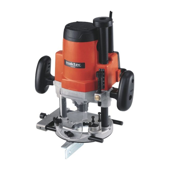
- Page 1 Router MODEL MT360 004924 005110 DOUBLE INSULATION I N S T R U C T I O N M A N U A L WARNING: For your personal safety, READ and UNDERSTAND before using. SAVE THESE INSTRUCTIONS FOR FUTURE REFERENCE.
-
Page 2: Specifications
SPECIFICATIONS Model MT360 Collet chuck capacity 12 mm or 1/2” Plunge capacity 0 - 60 mm 22,000 No load speed (min Overall height 300 mm Net weight 5.5 Kg Safety class • Due to our continuing programme of research and development, the specifications herein are subject to change without notice. - Page 3 power tools with your finger on the switch or plug- or storing power tools. Such preventive safety ging in power tools that have the switch on invites measures reduce the risk of starting the power tool accidents. accidentally. 12. Remove any adjusting key or wrench before 19.
- Page 4 SAVE THESE INSTRUCTIONS...
-
Page 5: Functional Description
FUNCTIONAL CAUTION: DESCRIPTION • Always be sure that the tool is switched off and unplugged before adjusting or checking function on the tool. Adjusting the depth of cut 004925 Place the tool on a flat surface. Loosen the lock lever and lower the tool body until the bit just touches the flat surface. - Page 6 Switch action 004927 CAUTION: • Before plugging in the tool, always check to see that the tool is switched off. • Make sure that the shaft lock is released before the switch is turned on. To start the tool, move the switch lever to the I position. To stop the tool, move the switch lever to the O position.
- Page 7 OPERATION 005112 CAUTION: • Before operation, always make sure that the tool body automatically rises to the upper limit and the bit does not protrude from the tool base when the lock lever is loosened. • Before operation, always make sure that the chip deflector is installed properly.
- Page 8 Install the straight guide on the guide holder with the thumb screw (B). Insert 004930 the guide holder into the holes in the tool base and tighten the thumb screw (A). To adjust the distance between the bit and the straight guide, loosen the thumb screw (B) and turn the fine adjusting screw (1.5 mm per turn).
- Page 9 Secure the templet to the workpiece. Place the tool on the templet and move 003695 the tool with the templet guide sliding along the side of the templet. NOTE: • The workpiece will be cut a slightly different size from the templet. Allow for the distance (X) between the bit and the outside of the templet guide.
- Page 10 When cutting, move the tool with the guide roller riding the side of the work- 003701 piece. 1. Bit 2. Guide roller Dust cover (For tool with the knob) 005113 To suit the tool when using in the inverted position with Makita Router Stand. This accessory prevents sawdust from being drawn through the tool in the inverted position.
- Page 11 Push down the lock lever onto the tool base. 004940 1. Support 2. Lock lever Then connect a vacuum cleaner to the vacuum head. 004941 To remove the vacuum head, raise the lock lever. Pull the vacuum head out of the tool base while holding the supports between thumb and finger.
- Page 12 Use a screwdriver to remove the brush holder caps. Take out the worn carbon 004942 brushes, insert the new ones and secure the brush holder caps. To maintain product SAFETY and RELIABILITY, repairs, any other mainte- nance or adjustment should be performed by Makita Authorized Service Cent- ers, always using Makita replacement parts.
- Page 13 “V”Grooving bit 005118 C00123 θ 90° 1/4” Dovetail bit 005119 C00124 θ 14.5 35° 15SE 3/8” 14.5 14.5 23° 15LE 3/8” 30° 3/8” Drill point flush trimming bit 005120 C00125 1/2” 3/8” 1/4” Drill point double flush trimming bit 005121 C00126 1/2”...
- Page 14 Slotting cutter 005122 C00127 1/2” 1/2” Board-jointing bit 005123 C00128 1/2” 1/2” 005124 Corner rounding bit 005125 C00129 1/4” 1/2” 1/4”...
- Page 15 Chamfering bit 005126 C00130 1/2” 005127 C00131 θ 30° 30° 30° E 1/4” 45° 45° 45° E 1/4” 60° 60° 60° E 1/4” Beading bit 005128 C00132 1/2” Cove beading bit 005129 C00133 1/4” 1/4” Ball bearing flush trimming bit 005130 C00134 1/4”...
- Page 16 Ball bearing corner rounding bit 005131 C00135 1/4” 1/4” Ball bearing chamfering bit 005132 C00136 θ 45° 45° 45° E 1/4” 60° 60° 60° E 1/4” Ball bearing beading bit 005133 C00137 1/4” 1/4” Ball bearing cove beading bit 005134 C00138 1/4”...
- Page 17 Double ball bearing round corner bit 005136 C00140 1/2”...
- Page 18 Memo...
- Page 19 Memo...
- Page 20 Makita Corporation 884528-4...
Need help?
Do you have a question about the MT360 and is the answer not in the manual?
Questions and answers