
Related Manuals for Panasonic WV-CS850A


Summary of Contents for Panasonic WV-CS850A
-
Page 1: Operating Instructions
Combination Camera Operating Instructions WV-CS850A Model No. WV-CS854AE Before attempting to connect or operate this product, please read these instructions carefully and save this manual for future use. - Page 2 ENGLISH VERSION We declare under our sole responsibility that the product to Vi deklarerar härmed värt fulla ansvar för att den produkt till which this declaration relates is in conformity with the stan- vilken denna deklaration hänvisar är i överensstämmelse dards or other normative documents following the provisions med standarddokument, eller andra normativa dokument of Directives EEC/73/23 and EEC/89/336.
-
Page 3: Table Of Contents
CONTENTS PREFACE ........................4 FEATURES ........................ 4 Camera Cleaning ....................5 Preset Data Uploading or Downloading ............5 PRECAUTIONS ......................5 CONSTRUCTION ..................... 7 SETUP ........................8 Setup Menu ....................... 8 Setup Menu Description ..................11 SETTING PROCEDURES ..................16 Menu Display ..................... -
Page 4: Preface
PREFACE Panasonic presents highly advanced CCTV tech- for use under extremely low lighting conditions : nology that meets the demands of new and ever- 0.06 lx for monochrome and 1 lx for colour. changing applications. It also assures clear display of pictures in which... -
Page 5: Camera Cleaning
• Preset positions may vary. If a preset position varies, delete the preset position and set the cor- rect preset position newly. • If a preset data of WV-CS850A Series is uploaded to lower level models (e.g. WV-CS850 Series), an error may occur and uploading may not be completed successfully. - Page 6 Use the camera under conditions where temperature is between –10°C - +50˚C (14˚F 122°F) [Recommended temperature: +40˚C (104˚F)], and humidity is below 90 %. The input power source is 220 V - 240 V AC for WV-CS850A, 24 V AC for WV-CS854AE.
-
Page 7: Construction
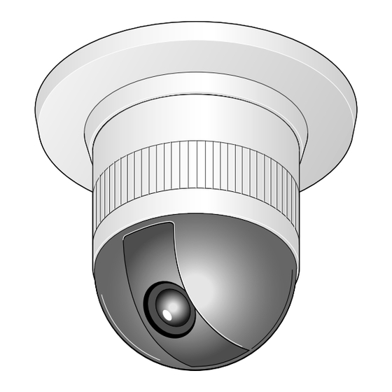
Alarm Input Connector y Camera Mounting Base w Alarm Output Connector u Panning Start Point e Video Output Connector i Fall Prevention Wire r Data Port o Decoration Cover t Power Cable for WV-CS850A !0 Dome Cover t* Power Cable for WV-CS854AE... -
Page 8: Setup
SETUP Setup Menu Setup menus are shown in the diagram below. Various kinds of setup are available to have the camera fulfill your requirements. Menus are built in a hierarchical structure from the Setup menu at the top down to Manual Mask Area Selection at the bottom. These menus are described in the following pages for reference prior to setup. - Page 9 The keys (switches) to use for setup are as shown in the table below. The joystick on the connected con- troller may also be used for setup. The table also shows the functions versus the operations of the individ- ual controllers. For further details, see the manual for the controller to be used. The switches and controls are abbreviated as SW and CTRL in the table.
-
Page 10: Setup Menu Description
Setup Menu Description PRESET (1) Position (POSITION SET) POSITION SET adjusts the camera picture by panning, tilting, zooming and focusing. See page 17 for the setting. (2) Preset Identification (PRESET ID) A preset ID (identification of up to 16 alphanumeric characters) can be displayed on the screen. See page 19 for the setting. - Page 11 AUTO PAN KEY This setting assigns SEQ, SORT, AUTO PAN or PATROL (PLAY) to the AUTO key on the controller. After setting this, the AUTO key performs as assigned. Note: AUTO PAN LED on the controller does not light if something other than AUTO PAN is assigned. DIGITAL FLIP ON/OFF Tilt range is limited within 0°...
- Page 12 (6) Password Lock ON/OFF (PASSWORD LOCK ON/OFF) This setting controls access to the PRIVACY ZONE to be free or limited. If PASSWORD LOCK ON is selected, the (DIS) follows the PRIVACY ZONE ON or OFF set on the SPECIAL 1 menu. (7) Cleaning ON/OFF This is for refreshing the electric-mechanical contacts built in the camera.
- Page 13 Notes: • The result of field setup of the mask area and level adjustment is fed back (effected) to the lens iris control in ALC mode. • Select OFF for SUPER-D2 on the ALC CONT menu when using only for outdoors. If ON is selected for the SUPER-D2 parameter, a shadow (black line) may appear at the boundary between the bright and the dim scene.
-
Page 14: Rs485 Communication
(7) White Balance (WHITE BAL) You can select one of two modes for white balance adjustment as follows: • ATW (Auto Tracing White Balance) In this mode, the colour temperature is monitored continuously and thereby white balance is set automatically. The colour temperature range for the proper white balance is approximately 2 600 - 6 000 K. -
Page 15: Setting Procedures
SETTING PROCEDURES The following setting procedures are described on the assumption that this model is used in combination with the WJ-SX550B Matrix Switcher and WV-CU550B System Controller. In case of using a controller other than the WV-CU550B, refer to the table on page 10. Menu Display D4 menu Setup Menu Display... -
Page 16: Preset
Setup menu Preset ** SET UP MENU ** Preset Menu Display PRESET 1 HOME POSITION 1. Displaying the preset menu directly SELF RETURN (1) Move the cursor to PRESET 1 and move the joystick to the AUTO MODE AUTO PAN KEY AUTO PAN right or left to select the position number to be set. - Page 17 ID:DOOR 33-64 data. When this happened, prepare a WV-CS850A having the initial factory settings. Download the factory settings into the Position setting menu controller and then upload to the camera whose data is ** POSITION 1 ** destroyed.
- Page 18 Preset setting menu Preset ID Setting 1. Move the cursor to PRESET ID on the preset setting menu and PRESET NO. 1* select ON or OFF by moving the joystick to the right or left. POSITION SET PRESET ID ON: Preset ID is displayed on the screen. ALC/MANUAL DWELL TIME OFF: Preset ID is not displayed.
- Page 19 To Set a Display Position for a PRESET ID PRESET NO. 1* 1. Move the cursor to POSI and press the CAM (SET) key. The 0123456789 ABCDEFGHIJKLM display position set menu appears. NOPQRSTUVWXYZ ().,'":;&#!?= 2. Using the joystick, move the ID to the desired position on the +-*/%$ÄÜÖÆÑÅ...
- Page 20 Preset setting menu Dwell Time Setting PRESET NO. 1* • Move the cursor to DWELL TIME and set a dwell time by moving the joystick to the right or left. Dwell time changes as follows: POSITION SET PRESET ID ALC/MANUAL DWELL TIME 1MIN 2MIN...
-
Page 21: Deleting Preset Positions
Setup menu Deleting Preset Positions ** SET UP MENU ** 1. Move the cursor to PRESET 1 and select the position number to PRESET 1 be deleted by moving the joystick. HOME POSITION SELF RETURN AUTO MODE AUTO PAN KEY AUTO PAN DIGITAL FLIP LOCAL/REMOTE... -
Page 22: Auto Mode Selection
Setup menu Auto Mode Selection ** SET UP MENU ** 1. To set auto mode PRESET 1 Move the cursor to AUTO MODE and select a mode by moving HOME POSITION SELF RETURN the joystick to the right or left. Modes change as follows: AUTO MODE AUTO PAN AUTO PAN KEY... -
Page 23: Auto Pan Key Setting
6. To set endless turn ON/OFF ** AUTO PAN ** Move the cursor to ENDLESS, and move the joystick to the right or POSITION SET START left to set endless turn ON or OFF. SPEED ••••|•••• ON: The camera pans from the start position to the end position, PAN LIMIT then keeps rotating in the same direction to return to the start ENDLESS... -
Page 24: Digital Flip On/Off
Setup menu DIGITAL FLIP ON/OFF ** SET UP MENU ** • Move the cursor to DIGITAL FLIP and select ON or OFF by mov- PRESET 1 ing the joystick to the right or left. HOME POSITION SELF RETURN OFF: Tilt range is limited from 0° to 90°. AUTO MODE AUTO PAN KEY AUTO PAN... - Page 25 2. Select a zone number by moving the joystick to the right or left, ZONE setting menu then press the CAM (SET) key. ** ZONE NUMBER 1*/8 ** PAN/TILT PUSH SET • A zone number followed by * (asterisk) indicates that the zone ZOOM/FOCUS PUSH SET has already been registered.
- Page 26 • To complete new settings and repeat another setting, move the cursor to SET and press the CAM (SET) key. The ZONE NUMBER Selection menu returns. • To cancel new settings and return to SPECIAL 1 MENU, move the cursor to DEL and press the CAM (SET) key.
- Page 27 3. Move the cursor to PUSH SET on the ZOOM/FOCUS line, then ZOOM/FOCUS setting menu press the CAM (SET) key. ZOOM/FOCUS is highlighted and “U ** DIRECTION(NESW) ** PAN/TILT PUSH SET ZOOM D/L FOCUS R” appears. ZOOM/FOCUS PUSH SET POSI U ZOOM D/L FOCUS R 4.
- Page 28 To Quit Editing AREA TITLE menu • To return to the Area Title menu, move the cursor to RET, then AREA TITLE 1* 0123456789 press the CAM (SET) key. ABCDEFGHIJKLM NOPQRSTUVWXYZ • To cancel one area title, move the cursor to RESET, in the AREA ().,'":;&#!?= TITLE menu, then press the CAM (SET) key.
- Page 29 PATROL LEARN with a Controller Having PATROL Key PATROL LEARN 1. Press the PATROL key and the CAM (SET) key simultaneously to start PATROL LEARN. The setup menu changes to show “LEARN- ING” and the starting point parameters are stored. 2.
- Page 30 Special 1 menu Alarm IN/OUT (ALARM IN/OUT) Move the cursor to ALARM IN/OUT, then press the CAM (SET) key. ** SPECIAL 1 ** PRIVACY ZONE OFF(ENB) ALARM I/O submenu appears. PROPO.P/T AREA TITLE ON(USER) Note: While the camera is in AF mode or the lens moves between PATROL STOP ALARM IN/OUT...
- Page 31 COAXIAL ALARM OUT Alarm output signals are supplied through the coaxial cable. 1. Move the cursor to COAX and select ON or OFF. 2. Press the CAM (SET) key. ON: The camera sends an alarm output signal via the coaxial cable after it turns to a preset position. OFF: The camera does not send the output signal.
- Page 32 NEW PASSWORD NEW PASSWORD 4. To change the password in step 3-3 above, move the cursor from NEW PASSWORD? ** OK to NEW PASSWORD, then press the CAM (SET) key. NEW 0 1 2 3 4 5 6 7 8 9 PASSWORD menu appears.
- Page 33 Electric Zoom ON/OFF (EL-ZOOM ON/OFF) Special 1 menu The electric zoom magnifies a scene 10-fold. With a 22-fold optical zoom lens, the camera is capable of 220-fold zoom. ** SPECIAL 1 ** PRIVACY ZONE OFF(ENB) PROPO.P/T AREA TITLE ON(USER) 1. Move the cursor to EL-ZOOM and select ON or OFF by moving PATROL STOP ALARM IN/OUT...
-
Page 34: Camera Setting
Setup menu Camera Setting ** SET UP MENU ** 1. To Display the Camera Setting Menu PRESET 1 HOME POSITION • Move the cursor to CAMERA , and press the CAM (SET) key. SELF RETURN AUTO MODE The camera setting menu is displayed. AUTO PAN KEY AUTO PAN DIGITAL FLIP... - Page 35 • The positioning of the CAMERA ID stops at the edges of the CAMERA ID screen. 0123456789 ABCDEFGHIJKLM • The CAMERA ID moves faster when the joystick is kept at the NOPQRSTUVWXYZ ().,'":;&#!?= right or left for one second or more. +-*/%$ÄÜÖÆÑÅ...
- Page 36 (2) ALC Mode with SUPER-D2 OFF Blinking 1. Move the cursor to the SUPER-D2 parameter and select OFF. (When you select MANUAL, SUPER-D2 is not available.) The item MASK SET appears on the menu. 2. Move the cursor to MASK SET and press the CAM (SET) key. The 48 mask areas appear on the monitor screen.
- Page 37 Camera setting menu 4. Shutter Speed Setting (SHUTTER) ** SET UP ** Note: When ON is selected for SUPER-D2 on the ALC CONT menu, CAMERA ID this item is not available. ALC/MANUAL SHUTTER To select electronic shutter speed, select OFF for SUPER-D2 in ON(MID) SENS UP X2 AUTO...
- Page 38 • When ON is selected for SUPER-D2 on the ALC CONT menu X2 AUTO X4 AUTO X6 AUTO X10 AUTO X16 AUTO X32 AUTO Notes: • When ON is selected for SUPER-D2 in the ALC CONT menu, FIX is not available for this item. •...
- Page 39 7. Use the joystick to match the vertical phases for both video output ** SYNC ** signals as closely as possible. (COARSE adjustment can be V PHASE incremented in steps of 22.5 degrees (16 steps) with the joystick.) COARSE 1(1--16) FINE •|•••••••...
- Page 40 (2) Automatic White Balance Control Mode (AWC) Camera setting menu 1. Display SET UP on the monitor screen. ** SET UP ** CAMERA ID (Refer to Setup Menu Display on page 16 for details on displaying ALC/MANUAL SHUTTER the SET UP menu on the monitor screen.) ON(MID) SENS UP X2 AUTO...
- Page 41 Camera setting menu 9. Motion Detector Setting (MOTION DET) ** SET UP ** CAMERA ID 1. Display SET UP on the monitor screen. ALC/MANUAL SHUTTER (Refer to Setup Menu Display on page 16 for details on display- ON(MID) SENS UP X2 AUTO ing the SET UP menu on the monitor screen.) SYNC...
- Page 42 Because the alarm signal is multiplexed on the video signal it may be mistakenly interpreted by other video equipment as a time code signal. Therefore, when this camera is not used in a Panasonic Intelligent CCTV System, select OFF to prevent the above from occurring.
- Page 43 Camera setting menu 11. Special 2 Menu (SPECIAL2) ** SET UP ** This menu lets you adjust and set up the picture quality to meet your CAMERA ID requirements. ALC/MANUAL SHUTTER • Display SET UP on the monitor screen. ON(MID) SENS UP X2 AUTO (Refer to Setup Menu Display on page 16 for details on display-...
- Page 44 (4) BW ** SPECIAL2 ** CHROMA GAIN •••• •••• Move the cursor to BW and select AUTO, ON or OFF by moving AP GAIN •••• •••• the joystick to the right or left. Default : OFF. PEDESTAL • ••••••• AUTO: The camera selects black and white mode if the picture is AUTO BURST(BW) dark, or colour mode if the picture is bright enough.
-
Page 45: Rs485 Setup
Confirm the system protocol and parameters prior to setting the com- munication parameters for the camera. The initial communication parameters for WV-CS850A and WV-CS854AE are shown on the RS485 setup menu below. Other than the on-screen-setup parameters, the 4-bit DIP switch may be used to select 2- line (Half Duplex) or 4-line (Full Duplex) communication. - Page 46 ALARM DATA Specifies alarm transmission mode depending on the protocol selected by the 8-bit DIP switch. POLLING: Transmits the alarm data in response to requests from the controller. AUTO 1: Transmits the alarm data each time an alarm signal is received in the camera. AUTO 2 (Default): Transmits alarm data at intervals of at least 5 seconds.
-
Page 47: Installation
INSTALLATION Precautions • The following steps of installation and connection should be taken by qualified service personnel or system installers and should conform to all local codes. • Make sure to switch the camera off before installation and connection. • Do not install the camera near the air outlet of an air conditioner. 1. - Page 48 8-bit DIP SW Switch 1, an 8-bit DIP switch, specifies unit number or returns to the factory default settings for Panasonic’s protocol. When the unit number 1-96* is selected, it should be set on the RS485 SET UP menu (see page 46).
- Page 49 Unit Unit Unit Switch position Switch position Switch position number number number...
- Page 50 Notes: • Defaults are marked with • BP stands for Bit Position. • Daisy chain connection is not available for Full Duplex. (Only for Panasonic’s system controllers) 3. Assemble the Camera 1. Mark the mounting holes on the ceiling, Reverse the disassembly procedure. Take using the removed camera mounting base care not to cut any cables.
- Page 51 3. Hook the Fall prevention wire on the camera 5. Tighten the fixing screw M3 (provided). mounting base. Notes: (1) Tighten the camera fixing screw with a screwdriver. (2) Follow the instructions given here to ensure that the camera and camera mounting base are installed safely.
-
Page 52: Connections
• The following connections should be made by qualified service personnel or system installers in accordance with all local codes. • See the reverse side of the cover page for mains lead connection. 220 V - 240 V AC (WV-CS850A) 24 V AC cable 24 V AC (WV-CS854AE) - Page 53 • RS485 Connection Brown T (B) Data transmission Orange T (A) Yellow R (B) Data reception Green R (A) Note: Use the cable that is described below for RS485 site communication. • Shielded, twisted pair cable • Low impedance • Wire gauge size is thicker than AWG #22 (0.33 mm •...
-
Page 54: System Connections
SYSTEM CONNECTIONS Combination camera Max. 64 cameras Matrix switcher Personal computer VTRs (up to 16) RS-232C port Alarm inputs Printer System status monitor Monitors (up to 16) ALARM BUSY ALARM BUSY ALARM BUSY ALARM BUSY BACK FORWARD IRIS BACK FORWARD IRIS BACK FORWARD... -
Page 55: Prevention Of Blooming And Smear
Therefore, the camera should be operated carefully in the vicinity of extremely bright objects to avoid smear or blooming. SPECIFICATIONS WV-CS854AE WV-CS850A Effective pixels 737 (H) x 575 (V) Scanning area 3.57 mm (H) x 2.67 mm (V), 1/4” Synchronization... -
Page 56: Accessories
AUTO FOCUS MANUAL/AUTO AUTO MODE OFF/SEQ/SORT/AUTO PAN/PATROL AUTO PAN KEY SEQ/SORT/AUTO PAN/PATROL PLAY Digital flip ON/OFF CAMERA ID preset ID, camera ID, area title : up to 16 characters SUPER-D2 ON/OFF MOTION DET ON/OFF ALARM IN 4 inputs (ALARM IN 1 - 4) ALARM OUT 2 outputs (ALARM/AUX1, B/W/AUX2) B/W mode... -
Page 57: Appendix
APPENDIX Shortcuts Shortcut operations are available to controllers having the CAM FUNCTION key. Pressing numeric key(s) for one digit up to three digits then CAM FUNCTION key implements the respective functions as follows. The CAM FUNCTION key is abbreviated to [CAM FUNC] here. Function Function Selecting a PRESET position From #1 to #64... - Page 58 Matsushita Electric Industrial Co., Ltd. Web Site : http://www.panasonic.co.jp/global/ N0701-1071 V8QA5749BN Printed in Japan N 19 Gedruckt in Japan Imprimé au Japon Impreso en Japón Stampato in Giappone 2001 © Matsushita Communication Industrial Co., Ltd. All rights reserved.
Need help?
Do you have a question about the WV-CS850A and is the answer not in the manual?
Questions and answers