
Related Manuals for Panasonic WV-CS650


Summary of Contents for Panasonic WV-CS650
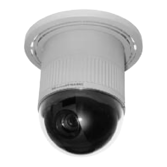
- Page 1 Combination Camera WV-CS650 WV-CS654 WV-CSR650 Before attempting to connect or operate this product, please read these instructions completely...
- Page 2 ENGLISH VERSION Vi erklærer os eneansvarlige for, at dette produkt, som We declare under our sole responsibility that the product to denne deklaration omhandler, er i overensstemmelse med which this declaration relates is in conformity with the den følgende standarder eller andre normative dokumenter i standards or other normative documents following the følge bestemmelserne...
- Page 3 IMPORTANT! / WICHTIG! / IMPORTANT! Do not install the camera near the air outlet of an air conditioner. The lens may become cloudy due to condensa- tion if the camera is used under the following conditions. • Rapid temperature fluctuations when switch- ing the air conditioner on or off.
-
Page 4: Table Of Contents
ACCESSORIES ..........38 Home Position Setting ......17 OPTIONAL ACCESSORIES ......38 PREFACE Panasonic presents highly advanced CCTV sensitivity CCD provides 480-line horizontal technology meets the demand of new and ever- resolution. With its advanced digital signal changing applications. This model is utilized... -
Page 5: Precautions
This product is designed for indoor use or input power source is 220 -240 V AC 50Hz locations where it is protected from rain and for WV-CS650, WV-CSR650, and 24 V AC moisture. 50Hz for WV-CS654. Turn the power off immediately and ask a qualified service person for servicing. -
Page 6: Construction
CONSTRUCTION (1) Data Cable (only for WV-CSR650) (6) Fall Prevention Wire (2) Video Output Connector (7) Decoration Cover (3) Power Cable for WV-CS650 and WV- (8) Cooling Holes CSR650 (9) Dome Cover (3*) Power Cable for WV-CS654 (4) Camera Mounting Angle... -
Page 7: Setup
SETUP Setup Menu This camera utilizes a user setup menu that is displayed on-screen. Setup Menu This setup menu contains various sub menus that form a tree-type structure as shown below. This menu is described in the "SETUP MENU DESCRIPTION". CAMERA SET UP MENU Preset... - Page 8 Note: The menus described in bold are displayed only when WV-CSR650 is used. UNIT TRANSMISSION DATA PARITY STOP XON/ WAIT ALARM DELAY NUMBER SPEED XOFF TIME DATA TIME Local/ Camera Remote Menu White Shutter Sensitivity Sync. Motion Balance Speed ON/OFF INT/LL Detector ON/OFF...
-
Page 9: Setup Menu Description
Setup Menu Description RS485 site communication (only WV-CSR650) Communication parameters • Full/Half duplex (page 31) • Transmission speed (2 400 - 19 200 bps) (page 11) • Parity bit, Stop bit, Flow control (page 11) • Retransmit time, Delay time, Alarm output (pages 11, 12) •... -
Page 10: Auto Mode
AUTO MODE AUTO MODE is for setting the movement of the camera. You can select from three automatic operation modes and one manual operation mode as follows: OFF mode: No automatic operation. The camera can be operated only manually. SEQ mode: The camera operates in the sequence of preset positions in numerical order. SORT mode: The camera operates in the sequence of preset positions counterclockwise from Pan/Tilt Starting Point. - Page 11 Generally, when a light from the background is too strong such as a spotlight, all objects except the main object in the picture are displayed darker because the lens iris is adjusted with respect to strong brightness. This model ignores strong brightness by masking the source of the strong brightness, thereby all objects are displayed clearly.
- Page 12 (7) White Balance (WHITE BAL) You can select one of two modes for white balance adjustment as follows: • ATW (Auto Tracing White Balance) In this mode, the colour temperature is monitored continuously and thereby white balance is set automatically. The colour temperature range for the proper white balance is approximately 2 600 - 6 000K.
-
Page 13: Setting Procedures
SETTING PROCEDURES The following setting procedures are described on the assumption that this model is used in combination with the WJ-SX550A matrix switcher and WV-CU550A system controller. If used with the WV-RM70 camera controller, refer to “WV-RM70” on page 5 for operation. Menu Display D4 menu Setup Menu Display... - Page 14 Changing the camera communication parameters 1. Display the SET UP MENU. Move the cursor to COM. SET UP DISABLE and press the CAM (SET) key to select COM. SET UP ENABLE. 2. Move the cursor to the item and select the parameter by moving the joystick to the left or right. You can remote control this camera by using a specified extension Setup menu unit such as a computer with a modem.
-
Page 15: Preset
CU550A. DELAY TIME Specifies the time to transmit the acknowledge request when communicating on a two-line connection. (OFF, 10, 20, 40, 100 ms) The factory setting is OFF. This menu appears only when a two-line communication is used. The settings become effective with closing of the SET UP MENU. Note: If the conditions of the communication for the camera became effective, the communication between the camera and the controller may not work. -
Page 16: Position Setting
Position Setting Preset setting menu 1. Move the cursor to POSITION SET and press the CAM (SET) key. PRESET NO.15*H The position set menu is displayed. POSITION SET PRESET ID ALC/MANUAL DWELL TIME SCENE FILE Position setting menu 2. To set panning/tilting positions Move the cursor to PUSH SET next to PAN/TILT and press the POSITION 15*H CAM (SET) key. - Page 17 Preset ID Setting Preset setting menu 1. Move the cursor to PRESET ID and move the joystick to the left or PRESET NO.15*H right to select ON or OFF. POSITION SET ON: Preset ID is displayed on the screen. PRESET ID ALC/MANUAL DWELL TIME OFF: Preset ID is not displayed.
- Page 18 To delete an edited PRESET ID PRESET NO.15*H Move the cursor to RESET and press the CAM (SET) key. 0123456789 ABCDEFGHIJKLM NOPQRSTUVWXYZ ().,'":;&#!?= +-*/%$ÄÜÖÆÑÅ SPACE COPY POSI RET RESET DOOR.... To set a display position for a PRESET ID Move the cursor to POSI and press the CAM (SET) key. The PRESET NO.15*H 0123456789 PRESET ID blinks and the display position set menu appears.
- Page 19 Dwell Time Setting Preset setting menu • Move the cursor to DWELL TIME and set a dwell time by moving PRESET NO.15*H the joystick to the left or right. Dwell time changes as follows: POSITION SET PRESET ID ALC/MANUAL DWELL TIME 1MIN 2MIN 3MIN...
-
Page 20: Deleting Preset Positions
Deleting Preset Positions Setup menu 1. Move the cursor to PRESET 1 and select the position number to *** SET UP MENU *** be deleted by moving the joystick. PRESET 1* HOME POSITION 15 SELF RETURN 10MIN AUTO MODE AUTO PAN FLIP-A-CHIP LOCAL/REMOTE LOCAL... -
Page 21: Auto Mode Setting
Auto Mode Setting Setup menu 1. To set auto mode *** SET UP MENU *** Move the cursor to AUTO MODE and select a mode by moving PRESET 1* the joystick to the left or right. Modes change as follows: HOME POSITION 15 SELF RETURN 10MIN... -
Page 22: Flip-A-Chip Setting
5. To set endless turn ON/OFF Move the cursor to ENDLESS, and move the joystick to the left or ** AUTO PAN ** POSITION SET START right to set endless turn ON or OFF. SPEED ...I..ON: The camera pans from the start position to the end position, ENDLESS then keeps rotating in the same direction to return to the start DWELL TIME... -
Page 23: Camera Setting
Camera Setting Setup menu 1. To display the Camera Setting Menu *** SET UP MENU *** PRESET 1* • Move the cursor to CAMERA , and press the CAM (SET) key. HOME POSITION 15 The camera setting menu is displayed. SELF RETURN 10MIN AUTO MODE... - Page 24 • The positioning of the CAMERA ID stops at the edges of the CAMERA ID.-- screen. 0123456789 ABCDEFGHIJKLM • The CAMERA ID moves faster when the joystick is kept NOPQRSTUVWXYZ ().,'":;&#!?= pressed for more than 0.5 seconds. +-*/%$ÄÜÖÆÑÅ • To return to SET UP for setting other items, move the cursor to SPACE ---- POSI RET RESET RET, and press the CAM (SET) key.
- Page 25 (2) ALC Mode with SUPER-D OFF Blinking 1. Move the cursor to the SUPER-D parameter and select OFF. (When you select MANUAL, SUPER-D is not available.) The item MASK SET appears on the menu. 2. Move the cursor to MASK SET and press the CAM (SET)key. The 48 mask areas appear on the monitor screen.
- Page 26 4. Shutter Speed Setting (SHUTTER) Camera setting menu Note: When ON is selected for SUPER-D on the ALC CONT menu, ** SET UP ** this item is not available. CAMERA ID ALC/MANUAL To select electronic shutter speed, select OFF for SUPER-D in the SHUTTER menu.
- Page 27 7. Synchronization Setting (SYNC) Camera setting menu 1. Display SET UP on the monitor screen. ** SET UP ** If necessary, refer to Setup Menu Display on page 10 for details CAMERA ID ALC/MANUAL on displaying the SET UP menu on the monitor screen. SHUTTER 2.
- Page 28 8. Move the cursor to FINE by using the joystick. The cursor starts blinking. 9. Use the joystick to match the vertical phase for both video output signals as closely as possible. Notes: • When the “|” cursor reaches the “+” end, it jumps back to “–”. At the same time, COARSE is incremented by one step to enable a continuous adjustment.
- Page 29 7. Move the cursor to “B.” Use the joystick to obtain the optimum amount of blue gain. The “I” cursor moves to the left or right. 8. Move the cursor to RET by using the joystick and press the CAM (SET) key to return to SET UP.
- Page 30 Camera setting menu 9. Motion Detector Setting (MOTION DET) ** SET UP ** 1. Display SET UP on the monitor screen. CAMERA ID ALC/MANUAL (Refer to Setup Menu Display on page 10 for details on SHUTTER displaying the SET UP menu on the monitor screen.) SENS UP SYNC WHITE BAL...
- Page 31 Because the alarm signal is multiplexed on the video signal it may be mistakenly interpreted by other video equipment as a time code signal. Therefore, when this camera is not used in a Panasonic Intelligent CCTV System, select OFF to prevent the above from occurring.
- Page 32 Camera setting menu 11.Special Menu (SPECIAL) This menu lets you adjust and set up the video signal of the camera ** SET UP ** to meet your requirements. CAMERA ID ALC/MANUAL • Display SET UP on the monitor screen. SHUTTER SENS UP (Refer to Setup Menu Display on page 10 for details on SYNC...
- Page 33 (4) Camera Picture Setting (UP SIDE DOWN) 1. In this menu, it is possible to turn the picture upside down. Use ** SPECIAL ** CHROMA GAIN ..I..this menu as described below. AP GAIN ..I..PEDESTAL .I..2. Move the cursor to UP SIDE DOWN and select ON by using the –...
-
Page 34: Installation
INSTALLATION 2. Setting the switches Precaution: The following installations should be made by Set the switches as follows: qualified service personnel or system installers. DIP Switches Setting the camera switches (only for WV-CSR650) • To reset the communication parameters to the factory preset values, for example, when operating multiple cameras in a daisy chain connection, set the switches inside the... - Page 35 b. Top cable exit NTSC PAL or NTSC Note: The dip switch is not for changing NTSC to PAL or PAL to NTSC. This switch is set at factory. Do not change the setting of this switch. The factory setting is ON. 3.
- Page 36 4. Hook the Fall prevention wire on the camera 2. Follow the instructions given here to mounting angle. ensure that the camera and camera mounting angle are installed safely. 3. When removing the camera from the camera mounting angle, loosen and press up the camera fixing screw (M3) by using a screwdriver.
-
Page 37: Connections
CONNECTIONS Precaution: The following connections should be made by qualified service personnel or system installers in accordance with all local codes. 220 - 240V AC (WV-CS650, WV-CSR650) 24V AC (WV-CS654) Data cable (Only for WV-CSR650) RS485 cable Video Output Cable... - Page 38 RS485 site connection Brown T (B) Data Transmission Orange T (A) Yellow R (B) Data Reception Green R (A) For daisy chain connection of multiple cameras, make sure to match each male connector with its female counterpart. Note: Use the cable that is described below for RS485 site communication by using WV-CSR650. •...
-
Page 39: System Connections
SYSTEM CONNECTIONS Combination Camera WV-CS650 WV-CS654 WV-CSR650 only or other models Max. 64 Cameras Matrix Switcher VTRs (up to 16) Personal Computer RS-232C Port CONTROL ALARM INPUT INPUT INPUT INPUT INPUT INPUT INPUT OUTPUT OUTPUT OUTPUT OUTPUT DATA RS-232C VIDEO OUT1... -
Page 40: Prevention Of Blooming And Smear
Selectable ON/OFF (SETUP MENU) Zoom Ratio x 10 Iris Range F1.2 - 64, CLOSE WV-CS650 and WV-CSR650 220 - 240 V AC, 50 Hz Power Source WV-CS654 24 V AC, 50 Hz 16W (WV-CS650 and WV-CS654) Power Consumption 19W (WV-CSR650) Ambient Operating 10°C - +50°C (14°F - 122°F) -
Page 41: Accessories
Panning Range 360° Endless Panning Angle Setting Possible (in Auto-Pan mode) Panning mode Manual/Sequential Position/Sort Position/Auto Pan Manual : Approx. 3°/s - 120°/s eight steps Panning Speed Sequence Position : Maximum approx. 240°/s Tilting Range 0 - 90° Tilting Mode Manual/Sequential Position/Sort Position Manual : Approx. - Page 42 Matsushita Electric Industrial Co., Ltd. Central P.O. Box 288, Osaka 530-91, Japan N0798-0 YWV8QA4984AN Printed in Japan N 30 Gedruckt in Japan Imprimé au Japon Impreso en Japón...
Need help?
Do you have a question about the WV-CS650 and is the answer not in the manual?
Questions and answers