Table of Contents
Advertisement
Quick Links
Advertisement
Table of Contents

Related Manuals for Hand Held Products Quick Check PC600


Summary of Contents for Hand Held Products Quick Check PC600
- Page 1 Quick Check® PC600 Bar Code Verifier User’s Guide...
- Page 2 Disclaimer Hand Held Products, Inc. (“Hand Held Products”) reserves the right to make changes in specifications and other information contained in this document without prior notice, and the reader should in all cases consult Hand Held Products to determine whether any such changes have been made. The information in this publication does not represent a commitment on the part of Hand Held Products.
-
Page 3: Statement Of Agency Compliance
Statement of Agency Compliance This device complies with part 15 of the FCC Rules. Operation is subject to the following two conditions: (1) this device may not cause harmful interference, and (2) this device must accept any interference received, including interference that may cause undesired operation. -
Page 4: Limited Warranty
The CE mark on the product indicates that the system has been tested to and conforms with the provisions noted within the 89/336/EEC Electromagnetic Compatibility Directive and the 73/23/EEC Low Voltage Directive. For further information please contact: Hand Held Products, Inc. Nijverheidsweg 9 5627 BT Eindhoven The Netherlands... - Page 5 Hand Held Products, Inc. extends these warranties only to the first end- users of the products. These warranties are nontransferable. The limited duration of the warranty for the Quick Check PC600 Bar Code Verifier is for two (2) years.
-
Page 7: Table Of Contents
Table of Contents Introduction ... 1 Getting Started with Quick Check Unpacking / What's Included ... 2 ® Quick Check PC Quick Start... 3 ® Quick Check PC Installation and Setup ... 6 ® Quick Check PC Features ... 11 Summary Grade Information ... - Page 8 Frequently Asked Questions ... 35 Glossary of Terms... 39 Additional Sources of Information ... 56 Electrical Specifications ... 57 Appendix A Messages... 59 Additional Data Messages:... 59 Error Messages: ... 59 Appendix B Notes for Windows ... 60 Additional Notes For Windows:... 60 Technical Assistance ...
-
Page 9: Introduction
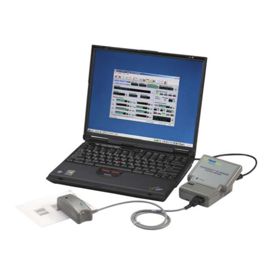
Introduction Hand Held Products is pleased to supply you with the Quick Check verification system. The instrument and software offer an easy-to-use and powerful combination that provides both pass/fail testing and full traditional and ISO/IEC verification with significant detail. This manual contains information on Quick Check It describes all the features and functions of the software and provides additional information about bar code symbol quality and the ANSI X3.182 / CEN EN1635 / ISO/IEC 15416 method of symbol verification. -
Page 10: Getting Started With Quick Check Pc
Getting Started with Quick Check Unpacking / What's Included When you first receive your Quick Check signs of shipping damage. If there is evidence of damage, please keep ALL packing materials and contact the delivery carrier as soon as possible for claim procedure. -
Page 11: Quick Check Pc Quick Start
® Quick Check PC Quick Start If you've used a Quick Check the manual and just click different parts of the control panel until you figure things out. That's okay. Quick Check interface for those familiar with the verification process and Windows-based software. - Page 12 • Press to turn unit off. • LED Status indicator: • The LED indicator is a 3-color indicator. • Green indicates that the interface module is functioning properly and has established connection with the Quick Check • Amber (yellow) indicates an error during communications. •...
- Page 13 Type D:\setup and click “OK”. (Note, if your CD is not drive “D” then you should type that letter instead of “D”.) The Install program will install the Quick Check drive. You will have the option of selecting an alternate location or folder/directory name for installation.
-
Page 14: Quick Check Pc Installation And Setup
Note: your settings will automatically be saved when you exit the Quick ® Check PC program. Note: For information on default settings, see the “Select Verification Parameters” in the following section. You are now ready to verify symbols. ® Quick Check PC software provides many useful functions not available with conventional verifiers. - Page 15 Keyboard shortcut or operation IF YOU DO NOT HAVE AN AVAILABLE COM PORT: STOP! For computers with USB and parallel ports (no serial ports) you can use a USB to serial converter (USB on PC end, male serial on end that connects to the QCDB09F female 9-pin serial port or a PC Card (PCMCIA) with a male serial adapter.
- Page 16 • If you have more than one Wand or Mouse Wand, select the one that most closely matches the size of the symbols you will be verifying. (See Help Topics or “Choose the Right Wand” under the “Using Quick Check PC”...
- Page 17 with known reflectance and dimensional performance characteristics. Scanning this symbol provides the Quick Check If you have not already done so, turn on the interface unit and start the Quick ® Check PC software. • Scan the calibration page (for the Mouse Wand) inside the manual to begin the calibration process.
- Page 18 • Check the connections at the interface module and the communications port. • Check to make sure the scanner is properly attached. • Check communications port setup. • Check the software configuration to ensure that the port setting is the same as the one to which you have connected the Quick Check Interface Module.
-
Page 19: Quick Check Pc Features
Wide-to-Narrow Ratio (if applicable) • Average Bar Error • Bar growth/shrinkage “LED” indicators • Status Bar • Advisory and prompt messages. • Scanner type/connection status ® PC saved file (if any) in ® PC's configuration and file ® PC with a... - Page 20 • Scan status (# of #) • Current COM port selection • Status “LED” red/green/off indicator in lower right to indicate whether the software is ready to accept scans or not. • “Battery Low” indicator in lower right hand corner (appears only during battery low conditions).
-
Page 21: Summary Grade Information
Next Scan • View the results of the one next scan (of a series). Scan Profile • View the scan reflectance profile graphically. Element Graph • View graph of element widths for current scan. Calculate X • Calculate the width of the narrow element in inches or centimeters (by entering measured symbol width). -
Page 22: General Scan Results
• Accumulated Scans • Indicates the total number of scans required (red indicators) for a symbol profile; the number of scans already completed (green bars). As scans are completed, red indicator bars turn green. Right-click to set: Number of scans •... -
Page 23: Reflectance Measures
: Allowable scan direction(s) (forward only, reverse only, both). • Speed Variance • Normal, Marginal, High -- whatever the case may be. Right-click to select/deselect : Display of speed variance information Reflectance Measures Both traditional and ISO/IEC parameters are displayed in this area. For further information on interpreting this data, see the “Traditional Print Quality Measures”... -
Page 24: Format Parameters
• High intensity” red or green indicates the achieved grade Right-click the “LED” area to select the minimum passing ISO/IEC grade. Format Parameters • Check Digit • Pass/Fail/Not Applicable Indicator (P, F, or N/A) and visual indicator (red, green, gray) Right-click the Check Digit “circle”... -
Page 25: Additional Data
: Code 39 : Interleaved 2-of-5 (ITF, I 2/5) : Codabar • Average Bar Error • Numeric measure of bar width deviation as a multiple of the X dimension • Pass/Fail indicator • Visual Pass/Fail indicator (Pass/Fail background displays green or red) •... -
Page 26: Status Bar
Displays current scan of required number of scans. • Com Port Connection • Displays the currently selected Com port • Com Port/Scanner Ready “LED” indicator (red, green, “off”) • Battery Low” Indicator • This displays when the interface unit's batteries are low. •... -
Page 27: Configuration And Settings
Configuration and Settings ® Quick Check PC software can be easily configured to meet one or more application requirements. Following are the user-configurable settings. Verification Parameters Number of Scans Set Scan Count Settings, Scan Right click Accumulated Scans display • Select from 1 to 50 individual scans to produce the final grade (ISO/IEC method). -
Page 28: Using Quick Check Pc
Message Length Right Click Msg. Length display • Select variable or fixed message length Note: If fixed-length message format is selected, it will apply to all symbologies enabled. Wide-to-Narrow Ratio Right Click W/N Ratio display • Enable/disable Wide-to-Narrow element ratio checking •... -
Page 29: Wand/Mouse Aperture Selection
If there is no applicable application standard, choose the light source that matches the scanner that will read the symbol (if known). If necessary, calibrate the verifier. If you have removed a wand, even if you reattach the same one, the program will require you to recalibrate. - Page 30 Hand Held Products calibration page (QCRFPG).. Scan smoothly. If you're not scanning properly, you'll be advised of the specific problem by the software. • Ten consecutive scans are required for calibration. An audio tone indicates a successful scan. Screen prompts will advise you of your progress.
-
Page 31: View Individual Scan Results
If you need to use a different wand (aperture), the Quick Check any Hand Held Products interchangeable wand. For scanning with a traditional Pen Wand, the plastic support and wand tip must both be flat against the scanning surface to maintain the proper scanning angle. Note: When using a Pen Wand, both the tip of the wand and the plastic alignment guide must be touching the surface. -
Page 32: View Scan Reflectance Profile
View Scan Reflectance Profile View the scan reflectance profile of a scan. The bar/space pattern is displayed below the analog signal. A Zoom feature allows detailed visual inspection of the symbol pattern and profile. Scan Profile View, Scan Profile Options include the display of specific areas in the symbol profile that determined the Decodability, Defects, and Minimum Edge Contrast values. -
Page 33: Notes
Notes You can add notes to any symbol report. Notes apply to all individual scans. Notes View, User Notes Reflectometer ® The Quick Check PC can serve as a reflectometer and return static reflectance readings. Reflectometer View, Reflectometer Select “Reflectometer” and place the wand over the area from which the reading is required. -
Page 34: Print Report
Select the file you want to open. If it was not stored in the default directory, select the proper drive and/or directory. Select the details to be included in either the symbol or scan report format. If no changes are required from the previous report format, you do not have to select these parameters and can go directly to “Print.”... -
Page 35: Context Sensitive Help
• Did the background and bar contrast (color) or reflectance meet the correct criteria for a bar code scanner to "see" the bar code? (At that time, scanners were primarily based on helium neon lasers which "sees" everything as if it had red glasses on.) •... - Page 36 "viewed" the bar codes. This was not the way any bar code scanner would "see" the bar code. A bar code scanner is an optical device and does not incorporate human eye optical properties when "looking"...
- Page 37 Numeric ranges exist within the alphabetic grades. Use of the numeric equivalents may provide greater assistance in determining symbol problems. The following illustration shows a Scan Reflectance Profile from a Quick Check PC scan of a symbol. To differentiate bars and spaces, a Global Threshold is established on the scan reflectance profile by drawing a horizontal line half way between the highest reflectance value and the lowest reflectance value seen in the profile.
- Page 38 D ≥ 40% F < 40% Modulation has to do with how a scanner “sees” wide elements (bars or spaces) in relationship to narrow elements, as represented by reflectance values in the scan profile. Scanners usually “see” spaces narrower than bars and scanners typically “see”...
- Page 39 This is controlled by the wide to narrow ratio, and ISO/IEC terms this as Reference Threshold. Decodability measures this printing accuracy and compares it to how a scanner would be able to read the bar code against a reference decode algorithm. The result is the available margin for the reading process.
-
Page 40: Common Corrective Actions
PC, the symbol will fail Decode even if all other parameters pass. Decode is a Pass/Fail parameter. The Scan Grade is the lowest grade received out of the eight parameters tested from a given scan profile. Even though an “A” grade might be achieved on most of the parameters, if a “C”... - Page 41 common corrective actions that can be attempted to remedy symbol quality problems. Problem: Low Symbol Contrast (SC) or PCS Possible Causes: • High Minimum Reflectance (Rmin) • Bars too “light” • Incorrect verification light source • Low Maximum Reflectance (Rmax) •...
-
Page 42: Error Messages
Possible Causes: • Small X dimension (<0.10”) makes narrow spaces appear too narrow. • Verifier aperture too large Potential Solutions: • Make narrow spaces slightly wider than narrow bars (if possible). • Check for proper verifier aperture size (see Wand/Mouse Aperture Selection Table on page 21.) Problem: High Defects Possible Causes:... -
Page 43: Frequently Asked Questions
Practice scanning smoothly, with little pressure on the wand. • Practice scanning the symbol, outside of Quiet Zone to outside of Quiet Zone in about one-half second. Scanner Missing, Scanner Disabled • The software is unable to detect the presence of a wand. •... - Page 44 Each symbology has its own characteristics. Basic characteristics of bar code symbologies are: • The number of element widths. • Two-width symbologies have only two element widths (wide and narrow). Codabar, Code 39, and Interleaved 2-of-5 are two-width symbologies. • Multiple-width symbologies have more than two element widths (expressed in multiples of the X dimension, as 1X, 2X, 3X, 4X).
- Page 45 Resources” for addresses. What is “verification” and how does it differ from “reading”? In bar code reading, a scanner/decoder attempts to decode a bar code symbol. If successful, the data is sent to a database. No judgment on quality is made.
- Page 46 ® The Quick Check PC provides a quick and comprehensive basis for a bar code quality program. Setting up a bar code quality program requires an understanding of the requirements of a given application, whether for in-house use or to satisfy customer requests.
-
Page 47: Glossary Of Terms
A physical opening that is part of the optical path in a device such as a scanner, photometer, or camera. Most apertures are circular, but they may be rectangular or elliptical. aperture diameter: The effective diameter of the optical system aperture. - Page 48 average edge: An imaginary line dissecting the irregularities of the character edge. background: The light area between and surrounding the bars of a printed machine-readable symbol. The background can be the substrate on which the symbol is printed or an over-printing of a suitable light color. bar: Any of the dark lines in a printed machine-readable symbol.
- Page 49 In two directions - specifically, backwards and forwards. Denoting that a machine-readable symbol can be read successfully either backwards or forwards. Denoting a scanner that can operate successfully either backwards or forwards. binary: Denoting a numbering system to base 2 in which numbers are expressed as combinations of the digits 0 and 1, with positional weighting based on powers of 2.
- Page 50 pattern of wide and narrow elements determines the character being encoded. The intercharacter gaps are spaces with a minimum nominal width of 1X. appropriate ISO/IEC JTC 1/SC 31 reference, when available. Code 128: A continuous, variable length, bar code symbology capable of encoding the full ASCII 128 character set, the 128 extended ASCII character set, and four non-data function characters.
- Page 51 The determination of the information encoded in a machine-readable symbol. decoder: As part of two-dimensional symbol and bar code reading systems, the electronic package that receives the signals from the scanner, performs the algorithm to interpret the signals into meaningful data and provides the interface to other devices.
- Page 52 The range of distances over which a scanner can reliably read a symbol of given characteristics. Equal to the range of the scanner minus its optical throw. discrete bar code symbol: A symbology in which the spaces between symbol characters (intercharacter gaps) do not contain information as each character begins and ends with a bar.
- Page 53 flexography: A method of direct rotary printing using resilient, raised image printing plates, affixed to variable repeat plate cylinders, inked by a roll or engraved metal roll that is wiped by a doctor blade, carrying fluid or paste-type inks to virtually any substrate. font: A set of characters of a specific style and size of graphic type.
- Page 54 intercharacter gap; intercharacter space: The space between the last bar of one symbol character and the first bar of the next in a discrete bar code symbology. See “discrete code,” “continuous code.” Interleaved 2-of-5 (ITF): A bar code symbology encoding the ten digits 0 through 9.
- Page 55 from several directions. Light sources for bar code reading equipment are typically infrared (900 nanometers peak), visible red (630 to 720 nanometers), and incandescent (400 to 900 nanometers). The source wavelength of He-Ne laser light is precisely 632.8 nanometers. linear symbol: A one-dimensional bar code symbol. An array (linear sequence) of rectangular bars and spaces that are arranged in a predetermined pattern following specific rules to represent elements of data that are referred to as characters.
- Page 56 Usually used in the form Modulo-10, Modulo-103, and the like. The type of algorithm used to calculate the check digit for certain bar code symbols. mouse wand: see “wand scanner”, “light scanner”. multi-row symbol; stacked symbol: Symbologies where a long message is broken into sections and "stacked' one upon another similar to sentences in a...
- Page 57 Lack of data output when a machine-readable symbol is scanned due to a defective symbol, incorrect orientation or speed of scan, scanner failure, or operator error. Compare to “misread.” normal: Perpendicular to the surface of a plane.
- Page 58 The degree to which a printed optical symbol complies with the requirements that are specified for it, such as dimensions, reflectance, edge roughness, spots, voids, etc., that will affect the performance of the scanner. See “verification.” print tolerance: An absolute measurement of deviation from a nominal print width, expressed as being plus or minus (+, -) so many millimeters or thousandths of an inch.
- Page 59 The percentage representing the number of successful reads per 100 attempts to read a particular symbol. An attempt is a single pass of the scanner, or a single trigger pull, depending upon the application. reader: A device used to capture the data encoded in a machine-readable symbol or other automatic data capture media.
- Page 60 A record of reflectance measured as a function of position during a scan across the entire bar code symbol. scan speed: The speed at which the scanning spot of a scanner passes across a symbol. Scan speed is expressed in centimeters per second or inches per second.
- Page 61 (R s ): The largest reflectance value in a space or quiet zone. speck: See “spot”. spectral response: The sensitivity of a scanner or other device to light of different wavelengths. specular reflection: Reflection from a surface in which the angle of reflection to normal equals the angle of incidence to normal.
- Page 62 readable symbol has been correctly composed and read. The symbol check character does not form part of the data encoded in the symbol. symbol contrast (SC): The reflectance difference between the points of highest and lowest reflectance respectively in a scan reflectance profile. symbol density;...
- Page 63 (1) An area of high reflectance in an area of a machine-readable symbol that is intended to be of low reflectance. See “speck,” “spot.” wand scanner: A handheld scanning device used as a contact bar code or OCR reader. See “light pen.”...
-
Page 64: Additional Sources Of Information
Compare to “delta code”. width error: The difference between nominal and measured bar (or space) widths, calculated from the scanner’s digital output or the optically measured bar (space) widths. X dimension: The specified width of the narrow elements in a machine- readable symbol. -
Page 65: Electrical Specifications
The Old Vicarage Haley Hill, Halifax, HX3 6DR West Yorkshire, England, UK Tel: +44 1422 368368 Fax: +44 1422 355604 Website: www.aimuk.org Europe Blue Tower, Avenue Louise, 326 BE 1050 Brussels Belgium Tel: +32 2 788 7800 Fax: +32 2 788 7899 Website: www.GS1.org North America... - Page 66 • Input Device Connector: 9-pin plastic “squeeze to release” male • Allows input from any existing or future Hand Held Products interchangeable wand • I/O Connector: 9-pin DB-9 Male • Interfaces the input box to the PC serial port • Power Connector: uses the existing Hand Held Products Quick Check AC charger •...
-
Page 67: Appendix A Messages
Appendix A Messages Additional Data Messages: • [nnn% Magnified ] • Magnification report (UPC/EAN) • [Total = nn X ] • Total number of elements in symbol • [Quiet Zones OK ] • Both Quiet Zones pass. Error Messages: • [BAD # System ] •... -
Page 68: Appendix B Notes For Windows
Appendix B Notes for Windows Additional Notes For Windows: If you have added a communications card to your system, you can have Windows set up your communications card by clicking “Start” on the Windows TaskBar, selecting “Settings” and then “Control Panels.” In the Control Panels window, select “Add New Hardware.”... -
Page 69: Online Technical Assistance
Telephone: (704) 998-3998, option 8, option 3 Telephone: (800) 782-4263, option 8, option 3 E-mail: latechsupport@handheld.com Brazil Telephone: +55 (21) 2178-0500 Fax: +55 (21) 2178-0505 E-mail: brsuporte@handheld.com Mexico Telephone: (704) 998-3998, option 8, option 3 E-mail: latechsupport@handheld.com Europe, Middle East, and Africa Telephone: +31 (0) 40 7999 393 Fax: +31 (0) 40 2425 672 E-mail: eurosupport@handheld.com... - Page 70 Hand Held Products provides service for all its products through service centers throughout the world. To obtain warranty or non-warranty service, return the unit to Hand Held Products (postage paid) with a copy of the dated purchase record attached. Contact the appropriate location below to obtain a Return Material Authorization number (RMA #) before returning the product.
-
Page 71: Online Product Service And Repair Assistance
Japan Telephone: +813-5770-6312 Fax: +813-5770-6313 E-mail: apservice@handheld.com Online Product Service and Repair Assistance You can also access product service and repair assistance online at www.handheld.com. - Page 72 Hand Held Products, Inc. 700 Visions Drive P.O. Box 208 Skaneateles Falls, NY 13153-0208 QCPC600-UG Rev D 3/07...
Need help?
Do you have a question about the Quick Check PC600 and is the answer not in the manual?
Questions and answers