Table of Contents
Advertisement
Quick Links
Download this manual
See also:
User Manual
Advertisement
Table of Contents

Related Manuals for Attero Tech unDIO2x2


Summary of Contents for Attero Tech unDIO2x2
-
Page 1: User Manual
2-in/2-out Dante Interface User Manual Date 08/30/2013 Revision 01 Attero Tech, LLC 1315 Directors Row, Suite 107, Ft Wayne, IN 46808 Phone 260-496-9668 • Fax 260-496-9879 www.atterotech.com 614-00013-01... -
Page 2: Important Safety Instructions
10. Protect the power cord from being walked on or pinched particularly at plugs, convenience receptacles, and the point where they exit from the apparatus. 11. Only use attachments/accessories specified by Attero Tech 12. Use only with the cart, stand, tripod, bracket, or table specified by the manufacturer, or sold with the apparatus. - Page 3 LLC, shipping costs prepaid, within two year from the date of purchase. This Limited Warranty is governed by the laws of the State of Indiana. It states the entire liability of Attero Tech, LLC and the entire remedy of the purchaser for any breach of warranty as outlined above.
-
Page 4: Table Of Contents
3.2.5 – Saving and Loading Settings.......................... 12 3.2.5.1 – Internal Presets ............................12 3.2.5.2 – Preset Files ............................. 12 4 – ARCHITECTS & ENGINEERS SPECIFICATION ............................13 4.1 – Device Specifications.............................. 13 APPENDIX A - Reference Documents................................A-1 Attero Tech LLC 2013 Page 3 614-00013-01... -
Page 5: Overview
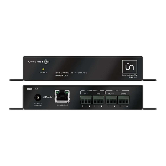
Connection to the Dante network is provided by a single Ethernet RJ45 connector on the back of the unit. The unDIO2x2 can be powered by a 12V DC wall wart (ordered separately) but it also supports the use of PoE instead. -
Page 6: Device Installation
2 x Balanced Audio outputs *Note: The unDIO2x2 has a label on one of the mounting flanges that shows the last 6 digits of the MAC address. This is important for initial device identification as these digits make up part of the devices default network name that is shown when the device is detected by Dante Controller. -
Page 7: Mounting
2.1 – Mounting Installation of the unDIO2x2 is very straight forward. It is recommended that the unit be secured to a flat surface with a screw through each mounting flange. Dimensions for mounting are show in the Figure 2 below. Use a No. 6 screw of a type and size that is applicable to the surface to which the unDIO2x2 will be attached. -
Page 8: Hardware Connections
2.2.1 – Input from an Unbalanced Source To connect a 2-wire unbalanced source to the unDIO2x2, connect the positive output of the unbalanced source to the positive input of the unDIO2x2. Connect both the source and unDIO2x2 input grounds together, and short the negative input of the unDIO2x2 to ground at the input of the unDIO2x2. -
Page 9: Output To A Balanced Destination
2.2.4 – Output to an Unbalanced Destination To connect the unDIO2x2 outputs to a 2-wire unbalanced input, connect the positive output to the destination’s positive input and connect the grounds together through the cable shield. Leave the unDIO2x2 negative output floating. -
Page 10: Device Configuration
(www.Audiante.com). Instructions on how to use this software and about setting up routes on a Dante network can also be found on their website. *Note: When using Dante controller, the unDIO2x2 will be shown using a default device name of unDIO2x2###### where ‘######’ is the last six characters of the devices MAC address. - Page 11 Once the files are transferred, the installer will show a completion message show whether the installation was successful or not. If the installation was unsuccessful for any reason, the final screen will show an error message. Attero Tech LLC 2013 Page 10 614-00013-01...
-
Page 12: Device Configuration
User Manual 3.2 – Device Configuration Once the required software is installed, click on the unIFY Control Panel icon in the programs list under Attero Tech. This will start the application. Figure 8 - Device Configuration window 3.2.1 – Selecting a Network Adapter In order to connect to a device the application needs to know what network adapter it should use to contact devices. -
Page 13: Device Controls
Settings in a device can be saved to an internal preset which can then be recalled at a later date. There are 10 internal presets, one of which is a default preset that is used to set device settings when the unDIO2x2 is first powered on. -
Page 14: Architects & Engineers Specification
The unit shall accept either +12V DC or IEEE802.3af standard PoE as power input. The unit shall be compliant with FCC Part15, CE and RoHS requirements. The unit shall be the Attero Tech unDIO2x2 I/O interface. 4.1 – Device Specifications... -
Page 15: Appendix A - Reference Documents
User Manual APPENDIX A - Reference Documents The following table lists the relevant reference documents. Document Title Revision unIFY Proxy Server Users Manual Attero Tech LLC 2013 Page A-1 614-00013-01... -
Page 16: Revision History
User Manual Document Information unDIO2x2 Document title: Document file name: unDIO2x2 User Manual.doc Revision number: <01> Issued by: Attero Tech Issue Date: 08/05/2013 Release Status: Revision History Revision Date Author Description of change 00_a 07/23/13 Initial Draft 00_b 08/05/13...
Need help?
Do you have a question about the unDIO2x2 and is the answer not in the manual?
Questions and answers