Table of Contents
Advertisement
HMC 8EH Burn Upgrades
APPENDIX F
UW Project Number: 206970
Ankrom Moisan Architects
PAGE 1 OF 123
March 16, 2020
APPENDIX F
THIS SECTION IS SUBMITTED FOR REFERENCE ONLY
ALL CONTRACTOR REQUIRED SCOPE IS INDICATED ON THE DRAWINGS
1. Narrative
2. Bluebeam markup
3. Datasheets
4.OOPC (Equipment List and Probable Cost)
AMA PROJECT NUMBER 192190
Section Prepared by Stantec
Advertisement
Chapters
Table of Contents

Subscribe to Our Youtube Channel
Related Manuals for Attero Tech unD6IO-BT


Summary of Contents for Attero Tech unD6IO-BT
- Page 1 HMC 8EH Burn Upgrades APPENDIX F UW Project Number: 206970 Ankrom Moisan Architects PAGE 1 OF 123 March 16, 2020 APPENDIX F THIS SECTION IS SUBMITTED FOR REFERENCE ONLY ALL CONTRACTOR REQUIRED SCOPE IS INDICATED ON THE DRAWINGS 1. Narrative 2.
- Page 2 HMC 8EH Burn Upgrades 27 41 16.20 AUDIO-VIDEO SYSTEMS NARRATIVE UW Project Number: #206970 Ankrom Moisan Architects PAGE 1 OF 2 March 25, 2020 PART 1 - GENERAL SUMMARY This section contains the general narrative that applies to the Audio-Video Sections of Division 27.
- Page 3 HMC 8EH Burn Upgrades 27 41 16.20 AUDIO-VIDEO SYSTEMS NARRATIVE UW Project Number: #206970 Ankrom Moisan Architects PAGE 2 OF 2 March 25, 2020 The equipment will reside in a 16 space cabinet rack with an Uninterruptible Power Supply. Therapy Room The Therapy room interactive audio video system is designed to provide video entertainment and interactive content via Multitouch video wall and applications loaded on connected computer like using a large iPad.
- Page 4 Touch Control Panel 4 Gang AV Box 1 HDMI Input 1 Bluetooth Reciever 1 USB connection for laptop control from touch monitor 1 Analog audio input panel AV Rack 1 Audio Digital Signal Processor 1 Video Matrix Switcher 1 BluRay Player 1 Audio Amplifier 1 Control Processor 1 OFE Computer...
- Page 5 Bluetooth Multi-I/O Wall Plate ® AES67 User Manual Date 7/25/2019 Revision 01_e Attero Tech, LLC 1315 Directors Row, Suite 107, Ft Wayne, IN 46808 Phone 260-496-9668 • Fax 260-496-9879 www.atterotech.com 614-00033...
- Page 6 Protect the power cord from being walked on or pinched particularly at plugs, convenience receptacles, and the point where they exit from the apparatus. 10. Only use attachments/accessories specified by Attero Tech 11. Unplug this apparatus during lightning storms or when unused for long periods of time.
- Page 7 LLC, shipping costs prepaid, within five years from the date of purchase. This Limited Warranty is governed by the laws of the State of Indiana. It states the entire liability of Attero Tech, LLC and the entire remedy of the purchaser for any breach of warranty as outlined above.
-
Page 8: Table Of Contents
5.3.1 – Control Interface Type ........................... 16 5.3.2 – API Documentation ............................16 5.3.3 – Using the Command interface ........................16 6 – ARCHITECTS & ENGINEERING SPECIFICATION ............................17 Device Specifications ........................................ 18 Attero Tech LLC 2019 Page 3 614-00033 Rev 01_e... -
Page 9: Overview
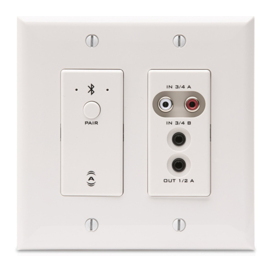
A 3.5mm TRS line level output on the front is also included. The unD6IO-BT is designed to fit into most dual gang US junction boxes and is PoE enabled, so all connectivity (power, control and audio data) is provided by a single CAT‐5e/6 cable. The unD6IO-BT’s unique mix of consumer style wired and wireless connectivity allows easy connection of a wide variety of user devices to a Dante™/AES67 network with no concerns... -
Page 10: Product Features
If power cycling the unit does not correct this problem, contact Attero Tech technical support. *Note: The unD6IO-BT has a label on the front of the metal housing at the top that shows the devices MAC address. This is important for initial device identification as the last six digits make up part of the devices default network name that is shown when the device is detected by Dante™... - Page 11 User Manual Figure 2 – unD6IO-BT Rear Panel Features Recessed RJ-45 (Dante™/AES67, Control and PoE) Recessed Factory Reset switch Attero Tech LLC 2019 Page 6 614-00033 Rev 01_e...
-
Page 12: Audio Signal Flow
User Manual 2.1 – Audio Signal Flow The following diagram depicts the internal signal flow for the unD6IO-BT. Figure 3 - unD6IO-BT Signal Flow Dante™ Channel I/O Function TX 1 Bluetooth Transmit– L Channel TX 2 Bluetooth Transmit– R Channel RCA L+R A, 3.5mm L+R In B, or sum of both... -
Page 13: Mounting And Installation
A typical installation will involve mounting the wall plate into a pre mounted 2-gang or larger wall box, standard drywall bracket or mud ring. Before starting, make sure the wall box where the unD6IO-BT is to be installed is pre-wired with a suitable CAT5e or better cable back to a PoE-enabled network switch or mid-span injector. - Page 14 User Manual Figure 5 - unD6IO-BT Dimensioned Drawings Attero Tech LLC 2019 Page 9 614-00033 Rev 01_e...
-
Page 15: Error Reporting
3.1 – Error Reporting The unD6IO-BT is equipped with error reporting features. Upon power up, the front panel LED will briefly light red and then change to green if the device boots successfully. If the LED remains on solid red, this indicates a device failure. -
Page 16: Device Features And Settings
To setup a device as the exclusive device, set the unD6IO-BT to “Exclusive” mode, clear the pairing list, and then pair the desired exclusive device to the unit. The unD6IO-BT makes a note of this device and from that point on, only that exclusive device will be allowed to reconnect to that particular unD6IO-BT when in range. -
Page 17: Bluetooth® Audio Bridging
The media bridging mode is an excellent solution for applications such as hospitality, retail and fitness center background music where users want to maintain call privacy while sharing media audio from their device’s media applications. Attero Tech LLC 2019 Page 12... -
Page 18: Call Bridging (Only)
VoIP and Web- based conferencing service failures. The application diagram below highlights the general system connectivity for a networked audio conferencing system utilizing Bluetooth call bridging with Attero Tech’s call bridging enabled networked audio products. -
Page 19: Bluetooth® Pass-Through Avrcp (Av Remote Control Protocol)
A+B (Mono sum of both input A and input B) 4.5 – Output Controls The unD6IO-BT features individual volume and mute controls for each of the audio outputs. The volume has a range from 0dB to -60dB in 1dB steps. -
Page 20: Configuration Workflow
IP addresses. By default, the unD6IO-BT is set to get a dynamic IP address. As with all Dante™/AES67 devices, if the unD6IO-BT does not find a DHCP server to retrieve an IP address from, it will give itself an local link address sometimes also known as an automatic private IP address (APIPA) instead. -
Page 21: Software Configuration And Control
5.3.3 – Using the Command interface In order to make use of the control interface, regardless of type, the unD6IO-BT and the controlling device need to be on the same physical subnet and need to have IP addresses in the same range. The control devices should then be able to converse with the unD6IO-BT without any further configuration necessary. -
Page 22: Architects & Engineering Specification
The Dante™/AES67 interface shall be compliant with the RoHS, WEEE and REACH directives. The Dante™/AES67 interface unit shall be Compliant with the EMI/EMC requirements for FCC and CE. The Dante™/AES67 interface unit shall be the Attero Tech unD6IO-BT. Attero Tech LLC 2019... -
Page 23: Device Specifications
Network Latency RoHS REACH Power Requirements 802.3af PoE PD compliant Power Consumption 5.5W Max Cable Quality: CAT-5e or better Physical Dimensions Width 3.54" Height 4.2" Depth 2" Weight 0.8 lbs. Attero Tech LLC 2019 Page 18 614-00033 Rev 01_e... - Page 24 I N S T A L L A T I O N I N S T R U C T I O N S Instrucciones de instalación Istruzioni di installazione Installationsanleitung Installatie-instructies Instruções de Instalação Instructions d´installation Power Conditioner Accessory Spanish Product Description German Product Description Portuguese Product Description...
- Page 25 PACPC1 Installation Instructions DISCLAIMER WARNING: Failure to read, thoroughly understand, and CSAV, Inc., and its affiliated corporations and subsidiaries follow all instructions can result in serious personal injury, (collectively, "CSAV"), intend to make this manual accurate and damage to equipment, or voiding of factory warranty! It is the complete.
- Page 26 Installation Instructions PACPC1 LEGEND Tighten Fastener Security Wrench Apretar elemento de fijación Llave de seguridad Befestigungsteil festziehen Sicherheitsschlüssel Apertar fixador Chave de segurança Serrare il fissaggio Chiave di sicurezza Bevestiging vastdraaien Veiligheidssleutel Serrez les fixations Clé de sécurité Loosen Fastener By Hand Aflojar elemento de fijación A mano...
- Page 27 PACPC1 Installation Instructions TOOLS REQUIRED FOR INSTALLATION 5/32" 5/32" 3/32" Security Security (Provided) (Provided) (Provided) PARTS A (1) (includes cord) D (1) B (1) F (1) 5/32" (Security) C (1) E (1) G (1) 3/32" 5/32" (Security) J (1) N (4) H (2) K (2) L (2)
- Page 28 Installation Instructions PACPC1 INSTALLATION Attaching to Drywall Attach bracket (D) to drywall using two #6 x 1" drywall screws (L). (See Figure 1) NOTE: Do NOT overtighten drywall screws. Proceed to Installing Conditioner. (K) x 2 Conditioner to be Attached Horizontally (L) x 2 Figure 1 Attaching to Wood Stud...
- Page 29 PACPC1 Installation Instructions Installing Conditioner Insert conditioner slots onto Phillips screws in bracket. (See Figure 5) Slide conditioner left or right. (See Figure 5) Remove conditioner to adjust Phillips screws in bracket as necessary for desired tension in mount. Conditioner Slots Conditioner Bracket...
- Page 30 Installation Instructions PACPC1...
- Page 31 PACPC1 Installation Instructions USA/International A 8401 Eagle Creek Parkway, Savage, MN 55378 P 800.582.6480 / 952.894.6280 F 877.894.6918 / 952.894.6918 Europe A Fellenoord 130 5611 ZB EINDHOVEN, The Netherlands P 31 (0)20 5708923 F 31 (0)20 5708989 Asia Pacific A Room 30I, Block D, Lily YinDu International Building LuoGang, BuJi Town, Shenzhen, CHINA.
- Page 32 Cisco 200 Series Smart Switches Small Business Build a Powerful, Easy-to-Use Basic Business Network at an Affordable Price The key to succeeding in today’s competitive business environment is parameters on switches in the network, automatically configuring investing resources wisely and getting the most value for your dollars. ports based on the connected endpoints, instructing the endpoints What if you could achieve business-class security and performance on correct settings to use, and applying appropriate settings to voice...
- Page 33 A Powerful Foundation for the Basic Business Network Cisco 200 Series Smart Switches help you build a business-class network for an affordable price. They provide just the right security, management, and QoS features you need to make the most of your business applications and productivity tools, without the costs or complexity of a managed switch.
- Page 34 IP LINK PRO IPCP Pro 250 Supports TouchLink Pro touchpanels ® IP LINK PRO CONTROL PROCESSOR Supports secure industry standard communications protocols ™ Supports LinkLicense One bidirectional RS-232 port with software handshaking One bidirectional RS-232/RS-422/ RS-485 serial port with hardware and software handshaking One IR/Serial port for one-way control of external devices...
- Page 35 DESCRIPTION SPECIFICATIONS The Extron IPCP Pro 250 is a versatile, high-performance control MEMORY processor designed for centralized AV control in small to medium- SDRAM 512 MB size applications. The IPCP Pro 250 is faster and more secure in Flash 4.5 GB ®...
- Page 36 AUDIO DSP DMP 64 Plus 6X4 ProDSP DIGITAL MATRIX PROCESSORS The DMP 64 Plus compact Digital Matrix Processor Four models with 6 mic/line inputs and 4 line outputs is a flexible audio processing solution that brings full Six channels of AEC - acoustic echo cancellation rack performance into a half rack space.
- Page 37 DESCRIPTION KEY FEATURES The Extron DMP 64 Plus series of compact Digital Matrix Four models with 6 mic/line inputs and 4 line outputs Processors features six DSP input channels with AEC, in only a half Six channels of AEC - acoustic echo cancellation rack space.
- Page 38 APPLICATION DIAGRAM Zoom Room Audio In this Zoom-enabled collaboration space, audio processing is handled by the DMP 64 Plus C V AT while connection to sources and displays is performed by an HC 404 system. Two Dante table mic arrays are connected via Ethernet to the DMP 64 Plus C V AT, where they receive all processing necessary for conferencing, including AEC.
- Page 39 OVERVIEW Six FlexInput Channels Compact Half Rack Size Up To 46x28 Total Inputs and Outputs With full DSP, including AEC, filters, Requires less rack space or Via Dante, expansion bus, analog, USB, dynamics, automixing, delay, and ducking easily fits under a table and VoIP Front to Back Ventilation Allows side by side and above or below...
- Page 40 SPECIFICATIONS AUDIO SYSTEM Codec support Various ITU, including wideband Gain Balanced output: 0 dB, unbalanced output: -6 dB Default settings Link speed and duplex level = autodetected Frequency response 20 Hz to 20 kHz, ±0.2 dB IP address = 192.168.1.254 THD + Noise <0.01%, 20 Hz to 20 kHz, at maximum level Subnet mask = 255.255.255.0...
- Page 41 PANEL DRAWINGS DMP 64 Plus C - Front DMP 64 Plus C - Back DMP 64 Plus C AT - Back DMP 64 Plus C V - Front DMP 64 Plus C V - Back DMP 64 Plus C V AT - Back WORLDWIDE SALES OFFICES A n a h e i m •...
- Page 42 DTP SYSTEMS DTP R HWP 4K 231 D Receives HDMI plus control and analog audio up to 230 feet (70 meters) DTP RECEIVER FOR over a shielded CATx cable HDMI – DECORATOR-STYLE Supports computer and video WALLPLATE resolutions up to 4K HDCP 2.2 compliant Supported HDMI specification features include data rates up to...
- Page 43 DESCRIPTION SPECIFICATIONS The Extron DTP R HWP 4K 231 D is a single-gang decorator-style SPECIFICATION receiver that works with Extron DTP-enabled products to send HDMI, audio, and bidirectional RS-232 and IR signals up to 230 feet Max. 4K Capabilities (70 meters) over a shielded CATx cable. The one-gang form factor Resolution and Refresh Rate Chroma Sampling Max Bit Depth per Color...
- Page 44 DTP SYSTEMS DTP HDMI 4K 230 Transmits HDMI plus control and analog audio up to 230 feet (70 meters) HDMI TWISTED PAIR EXTENDER over a shielded CATx cable Supports computer and video resolutions up to 4K, including 1080p/60 Deep Color Extron XTP DTP 24 shielded twisted pair cable is strongly recommended for optimal performance Bidirectional RS-232 and IR pass-...
- Page 45 DESCRIPTION SPECIFICATIONS The Extron DTP HDMI 4K 230 is a transmitter and receiver set for SPECIFICATION sending HDMI, audio, and bidirectional RS‑232 and IR signals up to 230 feet (70 meters) over a shielded CATx cable to Extron DTP ‑ ™ Max 4K Capabilities enabled products. It provides an economical and effective means for Resolution and Refresh Rate Chroma Sampling Max Bit Depth per Color...
- Page 46 TOUCHLINK PRO TLP Pro 725M 7" WALL MOUNT TOUCHLINK PRO TOUCHPANEL The Extron TLP Pro 725M is a 7" wall mount 7" capacitive touchscreen with 1024x600 resolution and 24-bit color depth TouchLink Pro Touchpanel with many enhanced ® Newly designed inside and out for the ideal balance features.
- Page 47 DESCRIPTION DESCRIPTION SPECIFICATIONS The TLP Pro 725M is a 7" wall mount touchpanel that offers stellar DISPLAY performance and superior design. Inside, there's a powerful new Screen type TFT Active matrix color LCD display quad-core processor and eight times more memory feeding the high Size 7"...
- Page 48 SWITCHERS SW USB Series A USB 2.0 compatible TWO AND FOUR INPUT USB A Four port output hub with 5V, 500mA SWITCHERS available on each output A Port Status LEDs A Multiple control points A RS-232 pass-through A Front panel security lockout A Host and Peripheral Emulation Mode - Rack Mounted USB SW4 USB Plus model...
- Page 49 FEATURES DESCRIPTION The SW USB Series are two- and four-input USB switchers that A USB 2.0 compatible – Supports 480 Mbps high speed communications and is backwards compatible with all prior USB provide integrator-friendly solutions for implementing USB 2.0 versions. compatible switching in professional AV environments.
- Page 50 APPLICATIONS SW USB for Switching and Control Extron SW USB switchers provide high performance switching and centralized control for KVM - Keyboard/Video/Mouse applications. A single keyboard and mouse connected to the SW USB switcher allow access, monitoring, and control of multiple USB-enabled devices from a remote location.
- Page 51 SPECIFICATIONS PANEL DRAWINGS USB specification USB 2.0 compatible ACTIVE USB EXEC USB data rates Low speed (1.5 Mbps), full speed (12 Mbps), high speed INPUT MODE (480 Mbps) OUTPUT SW2 USB USB INPUT USB SWITCHER SW2 USB - Front Connectors SW2 USB 2 female USB type B USB OUTPUTS HUB...
- Page 52 USB Extender Extends USB peripherals up to Plus Series 1,980 feet (600 meters) through a Gigabit Ethernet network Extends USB peripherals up to 330 feet (100 meters) point-to-point over one TWISTED PAIR EXTENDER FOR CATx cable USB PERIPHERALS Supports USB 2.0/1.0 devices with data rates up to 480 Mbps Choice of rack-mountable and Extend and switch USB peripherals...
- Page 53 Introduction The USB Extender Plus Series extends and switches USB signals Where longer distances are required or when pairing one transmitter from peripheral devices to a host computer up to 1,980 feet to multiple receivers, the USB Extender Plus Series transmitter and (600 meters) through a Gigabit Ethernet network or up to 330 feet receiver can be connected to a Gigabit Ethernet switch located up to (100 meters) point-to-point over one CATx cable.
- Page 54 Applications Extron Extron Extron Extron USB Extender Plus T USB Extender Plus R USB Extender Plus T USB Extender Plus R Twisted Pair Transmitter Twisted Pair Receiver Twisted Pair Transmitter Twisted Pair Receiver for USB Peripherals for USB Peripherals for USB Peripherals for USB Peripherals POWER POWER...
- Page 55 Specifications Form factors can be mixed and matched between transmitters and USB EXTENDER PLUS T/R SERIES receivers for mounting in all types of furniture and locations. USB host support xHCI (USB 3.0), EHCI (USB 2.0), OHCI/UHCI (USB 1.1) USB data rates Low speed (1.5 Mbps), full speed (12 Mbps), high speed (480 Mbps) Rack-Mount...
- Page 56 Specifications DTP CrossPoint 108 4K, DTP CrossPoint 86 4K, DTP CrossPoint 84 4K, DTP CrossPoint 82 4K Series specification Max. 4K Capabilities Resolution and Refresh Rate Chroma Sampling Max. Bit Depth per Color 4096 x 2160 at 30 Hz 4:4:4 3840 x 2160 at 30 Hz 8 bit 4096 x 2160 at 60 Hz...
- Page 57 Connectors DTP CrossPoint 108 4K ���������� 6 female HDMI type A 4 female RJ-45 DTP CrossPoint 86 4K ������������ 6 female HDMI type A 2 female RJ-45 DTP CrossPoint 84 4K ������������ 6 female HDMI type A 2 female RJ-45 DTP CrossPoint 82 4K ������������ 6 female HDMI type A 2 female RJ-45 Matrix video outputs (non scaled) Number/signal type...
- Page 58 Scaled resolutions �������������������������� 640x480 , 800x600 , 852x480 , 1024x768 , 1024x852 , 1024x1024 ,1280x768 1280x800 , 1280x1024 , 1360x765 , 1360x768 , 1365x768 , 1366x768 1365x1024 , 1400x1050 , 1440x900 , 1600x900 , 1600x1200 , 1680x1050 1920x1200 HDTV 480p , 576p , 720p , 1080i...
- Page 59 Supported formats — Pass through HDMI connectors �������������������� LPCM up to 7�1/24-bit/192kHz, Dolby TrueHD, Dolby Digital Plus, Dolby Digital EX, Dolby Digital 5�1, Dolby Digital 2/0 Surround, Dolby Digital 2/0, DTS-HD Master Audio, DTS-HD, DTS ES Discrete 6�1, DTS ES Matrix 6�1, DTS Digital Surround 5�1, DTS 2 Channel Analog conectors ��������������������...
- Page 60 Input gain adjustment��������������������� -18 dB to +80 dB, in 0�1 dB steps, adjustable per input Microphone volume range �������������� -100 dB to +12 dB DC phantom power ����������������������� +48 VDC, ±10% (inputs 1-4) switched on or off Audio output Number/signal type DTP CrossPoint 108 4K ����������...
- Page 61 Audio output — power amplifier (DTP CrossPoint 4K IPCP SA and DTP CrossPoint 4K IPCP MA models) Number/signal type SA models ������������������������������� 1 stereo or mono (2 channels total) MA models ������������������������������ 1 mono, 70 V Connector NOTE: This connector accepts wires of 22 AWG to 12 AWG� SA models �������������������������������...
- Page 62 Communications — external device (pass-through, unidirectional or bidirectional) (RS-232/IR over TP) NOTE: Protocol is mirrored between the connected TP endpoints and the "Over TP" ports on the DTP CrossPoint switcher� Signals from a control device pass into each DTP CrossPoint switcher "Over TP" port, are embedded with the TP signal, and sent to individual TP Tx or Rx endpoints for control of remote sink or source devices�...
- Page 63 Baud rate and protocol ������������ 300 to 115200 baud (9600 baud = default); 8 (default) or 7 data bits; 1 (default) or 2 stop bits; no parity (default), even, odd, mark, or space parity NOTE: The 5-pole ports support both hardware and software flow control� The 3-pole ports support software flow control�...
- Page 64 DTP CrossPoint 82 4K MA ������ 125 watts DTP CrossPoint 82 4K SA ������� 124 watts DTP CrossPoint 82 4K (non-IPCP) ������������������������������� 91�2 watts Remote power capability DTP CrossPoint 108 4K ���������� Supports up to eight endpoints (four DTP Tx, four DTP Rx) (Remote power not available in XTP and HDBaseT modes) DTP CrossPoint 86 4K ������������...
- Page 65 Regulatory compliance Safety �������������������������������������� CE, c-UL, UL EMI/EMC ��������������������������������� CE, C-tick, FCC Class A, ICES, VCCI Environmental �������������������������� Complies with the appropriate requirements of RoHS, WEEE Warranty ���������������������������������������� 3 years parts and labor NOTE: All Nominal levels are at ±10% NOTE: Specifications are subject to change without notice�...
- Page 66 JBL Commercial Series CSA 140Z CSA 180Z CSA 1120Z CSA 240Z CSA 280Z CSA 2120Z Commercial Series Amplifier Operation Manual...
- Page 67 Contents Important Safety Instructions ................3 JBL DECLARATION OF CONFORMITY ............5 1.0 Welcome ....................7 1.1 Features ....................7 1.2 Front Control Panels and Indicators ............8 1.3 Rear Panel Controls and Connectors............. 9 2.0 Setup ......................10 2.1 Unpacking Your Amplifier ..............10 2.2 Installing Your Amplifier .................10 2.3 Ensuring Proper Cooling ...............14 2.4 Choosing Input Wire and Connectors ...........14...
- Page 68 IMPORTANT SAFETY INFORMATION WARNING FOR YOUR PROTECTION READ THE FOLLOWING: KEEP THESE INSTRUCTIONS HEED ALL WARNINGS FOLLOW ALL INSTRUCTIONS THE APPARATUS SHALL NOT BE EXPOSED TO DRIPPING OR SPLASHING LIQUID AND NO OBJECT FILLED WITH LIQUID, SUCH AS VASES, SHALL BE PLACED ON THE APPARATUS The symbols shown above are internationally accepted symbols that warn of potential hazards with electrical products.
- Page 69 IMPORTANT SAFETY INFORMATION U.K. MAINS PLUG WARNING If you want to dispose this product, do not mix it with gen- eral household waste. There is a separate collection system for used electronic products in accordance with legislation A molded mains plug that has been cut off from the cord is that requires proper treatment, recovery and recycling.
- Page 70 EC - DECLARATION OF CONFORMITY Brand: Equipment Type: Commercial Audio Amplifiers Model names: CSA 140Z, CSA 180Z, CSA 1120Z, CSA 240Z, CSA 280Z, CSA 2120Z We, Harman International, declare under our sole responsibility that the product, to which this declaration relates, is in conformity with the following standards.
-
Page 72: Welcome
1.0 Welcome The JBL Commercial Series of Amplifiers are a professional tool designed and built ® for Installed sound applications. There are both single channel and two channel models. They provide amplification with a choice of low impedance, 70V or 100V outputs. - Page 73 1.2 Front Panel Controls and Indicators Figure 1.2 Front View of Single Channel Model CSA 1120 A. Output Volume Control B. Power Switch C. Illuminated ring around the output volume control will light green with signal presence while red indicates clipping, i.e. the signal has reached the threshold of audible distortion.
-
Page 74: Rear Panel Controls And Connectors
1.3 Rear Panel Controls and Connectors Figure 1.3 Rear View - CSA 1120Z AC Power Inlet – Detachable IEC Amplifier Output Connector C. Hi-Z Switch – Enables the 70V and 100V outputs and activates the 70Hz high pass filter D. Dual RCA Input Connector – Stereo, unbalanced sources will be summed together (Ch2-4) Audio Input Connector –... -
Page 75: Setup
2.0 Setup 2.1 Unpacking Your Amplifier Please unpack and inspect your amplifier for any damage that may have occurred during transit. If damage is found, notify the transportation company immediately. Only you can initiate a claim for shipping damage. We will be happy to help as needed. - Page 76 Figure 2.2.1 Dimensions CSA 1120 218.44 mm [8.6 in] 303.4 mm [11.9 in] Figure 2.2.2 Mounting Kit long angle bracket flat bracket front angle bracket rear angle brackets rear flat brackets...
- Page 77 Figure 2.2.3 Rack Mounting Two Units To install two units in your cabinet system, refer to Figure 2.2.3 and follow the steps below: Align two modules side by side and upside down with the front panel towards the same direction. Connect them with the flat bracket using the screws provided.
- Page 78 Figure 2.2.4 Rack Mounting A Single Unit To install a single unit, refer to Figure 2.2.4 and follow the steps below: Determine which side of the rack opening will be used for the amplifier and attach the long angle bracket to the other side at the front of the amplifier using the screws provided.
-
Page 79: Ensuring Proper Cooling
2.3 Ensuring Proper Cooling When using an equipment rack, keep a minimum space of 4 inches (10cm) from the top surface of the unit. Close any open spaces in the rack with blank panels. DO NOT block any air vents. The side walls of the rack should be a minimum of 2 inches (5 cm) from the amplifier sides. -
Page 80: Output Wiring And Connectors
2.5 Output Wiring and Connectors To drive distributed speaker systems designed to operate at 70V or 100V, connect to the corresponding output terminals. JBL recommends using prebuilt or professionally wired, high-quality, two-conductor, heavy gauge speaker wire. Speakers wires should be twisted cable, if possible. To prevent the possibility of short-circuits, the wires should be stripped back no greater than 6 mm (1/4 inch), see Figure 2.5. -
Page 81: Wiring Your Audio System
Figure 2.6 Wiring Audio System Professional audio system CSR-V LEVEL 2.6 Wiring Your Audio System Typical input and output wirings are shown in Figure 2.6. INPUTS: Connect input wiring for both channels using either the RCA or the Euro- block input for each channel. OUTPUTS: You may use either low impedance or high impedance speakers. -
Page 82: Connecting To Ac Mains
2.7 Connecting to AC Mains Connect your amplifier to the AC mains power source (power outlet) with the supplied AC power cord. First, connect the IEC end of the cord set to the IEC connector on the amplifier; then, plug the other end of the cord set to the AC mains. When properly connected to a live power source, the power ring should illuminate with a green color. -
Page 83: Operation
3.0 Operation 3.1 Precautions Your amplifier is protected from internal and external faults, but you should still take the following precautions for optimum performance and safety: Before use, your amplifier first must be configured for proper operation, including input and output wiring hookup. Improper wiring can result in serious operating difficulties. -
Page 84: Remote Volume Control
3.2 Hi-Z Switch When this switch is in the “OFF” position, the amplifier is configured to drive low impedance speakers, (4 Ohms ,minimum) The Hi-Z switch will switch in the built-in output transformer allowing the unit to drive 70V or 100V speaker systems directly when connected to the appropriate output terminals. -
Page 85: Troubleshooting
4.0 Troubleshooting CONDITION: No power to the amplifier so that the power ring is not illuminated. POSSIBLE REASON: The amplifier is not plugged into the power receptacle CONDITION: No sound or low sound. POSSIBLE REASON: The input signal is not present or at a very low level. POSSIBLE REASON: The Master Volume control is turned down. -
Page 86: Appendix A: Target Performance Specifications
Appendix A: Target Performance Specifications Performance CSA 140Z CSA 180Z CSA 1120Z CSA 240Z CSA 280Z CSA 2120Z Rated Power into 4 Ω or 8 Ω; 120W 120W 1kHz, ≤ 0.5% THD Number of Output Channels Insertion Loss (70V & 100V 1 dB maximum outputs) Input Sensitivity (8 Ω... -
Page 87: Appendix B: Contact Information
Appendix B: Contact Information For additional information, please consult JBL Professional Customer Service, your system installer or retailer. On The World Wide Web: www.jblcommercialproducts.com Professional Contacts, Outside the USA: Contact the JBL Professional Distributor in your area. A complete list of JBL Professional international distributors is provided at our U.S.A. - Page 89 JBL Commercial 8760 South Sandy Pkwy. Sandy, UT 84070 USA (801) 566-8800 Part Number:5040963 Issue: 01/14...
- Page 90 Control 26C/CT ® Professional Series – Background/Foreground Ceiling Speaker Key Features: • Coaxially mounted 165 mm (6.5 in) woofer with butyl rubber surround and 19 mm (¾ in) titanium coated diffraction-loaded tweeter • High power, wide frequency response and low distortion for high sound level capability •...
- Page 91 Control 26C/CT ® Professional Series – Background/Foreground Ceiling Speaker Input connection is conveniently provided on a removable locking support to the T-channel grid in suspended ceiling installations. After the connector (included), providing secure connection via screw-down speaker is fitted through the cutout, it is held securely in place via three terminals and allowing a system to be prewired before installing the mounting tabs which tighten onto the C-plate, if used, or directly onto speaker for fast snap-on convenience.
- Page 92 Control 26C/CT ® Professional Series – Background/Foreground Ceiling Speaker 1/3 Octave Polars: 1/3 Octave Polars...
- Page 93 Control 26C/CT ® Professional Series – Background/Foreground Ceiling Speaker Architectural Specifications: The loudspeaker shall be of in-ceiling design, consisting of a 165 mm up to 22 mm (7/8 in) outside diameter. The external wiring shall be (6.5 in) low frequency transducer, a coaxially-mounted 19 mm (¾ in) accomplished via a removable lockable wiring connector with screw- high frequency transducer, and frequency dividing network installed in down terminals to provide both secure wire termination and prewiring...
- Page 94 Slim 5 Series versatile rack frame system satisfies many 19” equipment racks design requirements • Available in 20” and 26” useable depths to accommodate deeper equipment • Wide range of cabinet options makes rack adaptable to a multitude of different installation environments •...
- Page 95 Slim 5 Series basic dimensions all dimensions in inches unless otherwise noted [all dimensions in brackets are in millimeters] top view bottom view top view .63 [16] 5-X/5-X-26 (optional side removable 4-1/2” 19.98 [507] / 10.50 [267] panels sheet fan knockout 25.98 [660] metal) .75 [19]...
- Page 96 Slim 5 Series basic dimensions all dimensions in inches unless otherwise noted [all dimensions in brackets are in millimeters] thermolaminate top view thermolaminate side panel steel side panel .75 [19] .63 [16] 1.74 [45] rear 21.27 [540] overhang .375 [10] .375 [10] side side overhang...
- Page 97 96-939/ rev f / 11-16-15 Rackmount Power Strips EIA/TIA Compliant EXCEPTIONAL SUPPORT & PROTECTION ™ Rackmount units provide economical power distribution PD-915R / PD-915RC-20 / PD-920R-NS / PD-920R / PD-920RC-20 Features • 8 circuit breaker protected rear outlets front view PD-815R-PL •...
- Page 98 Rackmount Power Strips basic dimensions All dimensions in inches [Bracketed dimensions are in millimeters] Middle tlantic Products TOP VIEW 8.75 [222] FRONT VIEW (PD-815RA-PL) REAR VIEW 1.75 [44] (PD-920R-NS, PD-920R, PD-920RC-20) 19.00 [483] (PD-920R-NS, PD-915R, PD-915RC-20, PD-920R, PD-920RC-20) (PD-815R-PL) (PD-815R-PL / PD-815RA-PL) (PD-915R-PL) (PD-915R) Power Cord/...
- Page 99 PD Series high density power strips feature a slim, low-profile design and staggered outlets slim power strips to accommodate plug-in power supplies • UL Listed and CSA certified (PD-2420SC-NS UL Listed only) • (1) 15 or 20 amp circuit depending on model •...
- Page 100 PD Series Slim basic dimensions all dimensions in inches unless otherwise noted [all dimensions in brackets are in millimeters] PD-24XXSC-XX PD-815SC-XX PD-715SC-NS circuit breaker ground stud 1.71 [43] Note: 1.46 [37] PD Slim Series Includes Signalsafe™ Power Cord Technology # of Plug In Outlet Outlet Power Supplies...
- Page 101 UPS Series uninterruptible power supply with energy saver design that is optimized to address uninterruptible power supply the needs of A/V systems • Pure Sine Wave technology with Automatic Voltage Regulation to improve the quality of power provided to the A/V system •...
- Page 102 UPS Series basic dimensions UPS-IPCARD Rackmount Uninterruptible Power Supply (UPS) shall be Middle Atlantic Products model # UPS- __ R__ (refer to chart). UPS shall be line interactive Web based control shall be enabled on non-internet enabled Middle Atlantic with AVR. Unit shall measure 19.00” W x 3.50” H x 19.00” D and occupy Products UPS by UPS-IPCARD, which shall be installed into the Expansion 2 rackspaces.
- Page 103 UPS Series basic dimensions all dimensions in inches unless otherwise noted [all dimensions in brackets are in millimeters] UPS-2200/1000 Series side view top view side view bottom view 19.0 [483] 17.047 [433.00] rear mounting range 17.829 19.291 19"[483] [452.9] [490] to 32"[813] 19.000 [482.6] front view...
- Page 104 UPS Series basic dimensions all dimensions in inches unless otherwise noted [all dimensions in brackets are in millimeters] UPS-1000R Series UPS-2200R Series Nominal Input Voltage 120 V 120 V Input Voltage Range 80VAC – 145VAC 80VAC – 145VAC Input Input Frequency 60 Hz +/- 3 Hz (auto sensing) 60 Hz +/- 3 Hz (auto sensing) Input Protection Type...
- Page 105 UPS Series basic dimensions all dimensions in inches unless otherwise noted [all dimensions in brackets are in millimeters] UPS-1000R Series UPS-2200R Series Communication Software Middle Atlantic Power Manager™ Middle Atlantic Power Manager™ Self-Test Manual Self-Test via front panel Manual Self-Test via front panel Auto-Charger/ Auto-Restart Primary: - RS232 Communication + Control...
- Page 106 Planar UltraRes UR9851 Touch Interactive 4K LCD Display The Planar® UltraRes™ UR9851 Touch is a 98" Ultra HD display that combines multi-touch experience with stunning 4K image clarity. With 32 simultaneous touch points, the Planar UltraRes UR9851 Touch is a fully integrated solution, delivering an elegant design and more accurate multi-touch experience.
- Page 107 Pixel Pitch 0.562mm Weight 330 lb (150 kg) Weight (Shipping) 480 lbs (218 kg) Backlight 100-240V; 50/60Hz Line Voltage Power Consumption (typ) 410W Operating Temperature 0° to +35°C (32° to 95°F) at up to 1500m, 0° to +30°C (32° to 86°F) at up to 3000m Humidity 20 - 85% RH (non-condensing)
- Page 108 1/14/2020 Puget Echo Pro Tech Specs https://www.pugetsystems.com Home / Desktops / Echo / Echo Pro Tech Specs echo pro A compact PC with room for a dedicated video card. Chassis: Silverstone FTZ01 Color: Black Material: Aluminum fame, steel body Type/Size: Small Form Factor Case Window: No Dimensions Height: 376 mm (14.8 in)
- Page 109 1/14/2020 Puget Echo Pro Tech Specs Processing Socket: 1151 CPU: Intel Socket 1151 for 9th Generation Processors Form Factor: Mini-ITX Chipset: Intel Z390 Expansion Slots: Slot 1: PCI Express 3.0 x16 Memory: Type: DDR4 2666 MHz Number of Slots: 2 Max per Slot: 32 GB Max Supported: 64 GB Connections:...
- Page 110 1/14/2020 Puget Echo Pro Tech Specs Front Ports: 1. Reset Switch 2. Power LED 3. HDD LED 4. Power Switch 5. USB 3.0 Port(s) 6. Front Headphone Jack 7. Front Microphone Jack 8. USB 3.0 Port(s) Benefits of Puget Systems Echo Pro Highly Reliable Product Line https://www.pugetsystems.com/nav/echo/III/specs.php...
- Page 111 1/14/2020 Puget Echo Pro Tech Specs All components in our product line are reviewed weekly. Any trends in failure rates are acted upon immediately, leaving us with a highly reliable product line that continues to improve. We do not add a part to our product line unless we feel we can stand behind it.
- Page 112 1/14/2020 Puget Echo Pro Tech Specs When you're shipping as many computers a day as Puget Systems, it can be challenging to make sure nothing is overlooked when you have so many things that you want to give personal attention. To ensure nothing gets missed, we have a comprehensive checklist to step our techs through the process.
- Page 113 How to use Wireless Stereo Headphone System Operating Instructions Mode d’emploi 4-429-926-12(1) ©2012 Sony Corporation Printed in China MDR-RF985RK Transmitter unit Headphones unit input signal RF transmission output signal Ⓧ ® noise level (low) compression decompression...
- Page 114 Utilisation Wireless Stereo Headphone System Operating Instructions Mode d’emploi MDR-RF985RK...
- Page 115 DATE: 12/4/2019 PROJECT: Video Wall Project Summary DESIGN 1 2W x 2H ABOUT LEYARD & PLANAR FOR MORE INFORMATION: Leyard and Planar, a Leyard Company are global leaders in leading-edge video wall display 855-748-8199 technology, providing premier LED and LCD video wall solutions for the world’s most demanding applications with the highest performance requirements.
- Page 116 SPECIFICATION DATA 1 DESIGN 1 Product Family Clarity Matrix G3 Product Model LX46U-L-ERO Video Controller Model VC4H-BP+ Total Number of Panels/Cabinets (Displays) Total Number of Display Mounts Video Wall Configuration 2W x 2H Display Orientation Landscape Display Brightness (nits) Redundant Signal Configured Redundant Power Configured Fiber Option Configured MultiTouch Option Configured...
- Page 117 SPECIFICATION DATA 2 DESIGN 1 Product Family Clarity Matrix G3 Product Model LX46U-L-ERO External Components - Rack Remote Power Supplies Remote Power Supply Modules Video Controller Quantity Video Extender Quantity Rack Unit Spaces Required (RU) Cabling Requirements Primary Video Extension Cables Primary Power Cables (AC) Primary Power Cables (DC) Energy Usage...
- Page 118 POWER CABLE ROUTING DESIGN 1 POWER CABLE LEGENDS www.leyard.com | www.planar.com Page 4/6 © Leyard & Planar 2019...
- Page 119 VIDEO CABLE ROUTING DESIGN 1 VIDEO CABLE LEGENDS www.leyard.com | www.planar.com Page 5/6 © Leyard & Planar 2019...
- Page 120 DESIGN DRAWING DESIGN 1 0.50ft 7.15ft 0.50ft 0.50ft 40.32in 34.87in 34.87in 4.45in 4.45in 5.45in 29.42in 10.90in 10.90in 29.42in 8.23in 18.62in 18.62in 14.17in 14.17in 35.63in 9.20in 35.80in 9.69in 22.79in 22.79in 4.23ft 8.62in 8.62in 8.62in 8.62in 14.17in 14.17in 35.63in 9.20in 35.80in 9.69in 18.34in 18.34in 5.45in...
- Page 121 8EH BURN UPGRADES-UW PROJECT Seattle WA 1/7/2014 Preliminary Audiovisual Systems Cost Summary CONTROL CONTRACTOR EQUIPMENT EQUIPMENT PROGRAMMING TOTAL TOTAL Play Room 48,976 17,141 66,117 66,117 Therapy Room 56,527 19,784 76,311 76,311 GRAND TOTAL 142,428 General Notes Amounts above do not include the cost of raceways, conduits, or back boxes Sheet Notes...
- Page 122 80w/ch 2ch 70v Amplifier, .5ru A2 JBL Control 26CT 70v Ceiling Speaker System AES67 Networked Audio Wall Plate - 4x2 Multi A3 Attero tech unA610-BT I/O with Bluetooth A4 Extron DMP 64 Plus C AT 6x4 Digital Matrix Processor w/ AEC and Dante...
- Page 123 80w/ch 2ch 70v Amplifier, .5ru A2 JBL Control 26CT 70v Ceiling Speaker System AES67 Networked Audio Wall Plate - 4x2 Multi A3 Attero tech unA610-BT I/O with Bluetooth A4 Extron DMP 64 Plus C AT 6x4 Digital Matrix Processor w/ AEC and Dante...
Need help?
Do you have a question about the unD6IO-BT and is the answer not in the manual?
Questions and answers