Sign In
Upload
Manuals
Brands
YOKOGAWA Manuals
Transmitter
YTA320
User Manuals: YOKOGAWA YTA320 Temperature Transmitter
Manuals and User Guides for YOKOGAWA YTA320 Temperature Transmitter. We have
5
YOKOGAWA YTA320 Temperature Transmitter manuals available for free PDF download: User Manual
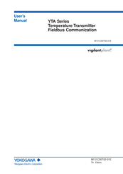
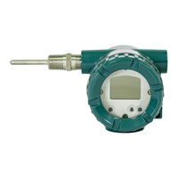
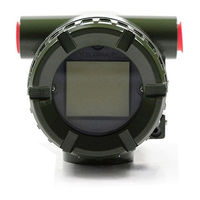
YOKOGAWA YTA320 User Manual (96 pages)
YTA Series Temperature Transmitter Fieldbus Communication
Brand:
YOKOGAWA
| Category:
Transmitter
| Size: 1 MB
Table of Contents
Table of Contents
2
1 Introduction
6
Regarding this Manual
6
For Safe Use of Product
7
Warranty
7
ATEX Documentation
8
2 Part Names
10
3 About Fieldbus
11
Outline
11
Internal Structure of YTA
11
System/Network Management VFD
11
Function Block VFD
11
Logical Structure of each Block
11
Wiring System Configuration
12
4 Getting Started
13
Connection of Devices
13
Host Setting
14
Bus Power on
14
Integration of DD
15
Reading the Parameters
15
Continuous Record of Values
15
Generation of Alarm
15
5 Configuration
16
Network Design
16
Network Definition
16
Definition of Combining Function Blocks
17
Setting of Tags and Addresses
18
Communication Setting
19
VCR Setting
19
Function Block Execution Control
20
Block Setting
20
Link Object
20
Trend Object
20
View Object
21
Parameters of Transducer Block
27
Parameters of AI Function Block
29
Parameters of DI Function Block
30
A Setting When Sensor Input 2 Is Not Connected
30
6 In-Process Operation
31
Mode Transition
31
Generation of Alarm
31
Indication of Alarm
31
Alarms and Events
31
Simulation Function
32
Operation of Integral Indicator
32
7 Errors and Warnings
35
Error and Warning Indications
35
Checking with LCD
35
Checking with DEVICE_STATUS_1 to _8 of Resource Block
38
Precautions on Warnings
42
8 Handling Caution
43
Installation of Explosionproof Type Transmitters
43
CSA Certification
43
CENELEC ATEX Certification
44
FM Certification
48
SAA Certification
51
Iecex Certification
51
9 General Specifications
55
Standard Specifications
55
Optional Specifications
56
Appendix 1. List of Parameters for each Block of the Yta
60
A1.1 Resource Block
60
A1.2 al Function Block
62
A1.3 Dl Function Block
64
A1.4 Transducer Block
65
A1.5 Unit and Code
69
APPENDIX 2. Parameters for Basic Settings, and How to Make and Change the Settings
70
A2.1 Basic Settings and Corresponding Parameters
70
A2.2 Making and Changing Basic Parameter Settings
71
A2.3 Setting up the Transducer Block
71
A2.4 Setting up AI Blocks
74
A2.5 Setting up DI Blocks
75
Appendix 3. Function Block Diagram
77
A3.1 AI Block Function Diagram
77
A3.2 DI Block Function Diagram
77
A4.1 Function Diagram
78
A4.2 Functions of PID Block
78
Appendix 4. Pid Block
78
A4.3 Parameters of PID Block
79
A4.4 PID Computation Details
81
A4.4.1 PV-Proportional and -Derivative Type PID (I-PD Control Algorithm
81
A4.4.2 PID Control Parameters
81
A4.5 Control Output
81
A4.5.1 Velocity Type Output Action
81
A4.6 Direction of Control Action
81
A4.7 Control Action Bypass
81
A4.8 Feed-Forward
81
A4.9 Block Modes
82
A4.9.1 Mode Transitions
82
A4.10 Bumpless Transfer
82
A4.11 Setpoint Limiters
83
A4.11.1 When PID Block Is in Auto Mode
83
A4.11.2 When PID Block Is in Cas or Rcas Mode
83
A4.12 External-Output Tracking
83
A4.13 Measured-Value Tracking
83
A4.14 Initialization and Manual Fallback (Iman)
84
A4.15 Manual Fallback
84
A4.16 Auto Fallback
84
A4.17 Mode Shedding Upon Computer Failure
84
A4.17.1 Shed_Opt
84
A4.18 Alarms
85
A4.18.1 Block Alarm (BLOCK_ALM)
85
A4.18.2 Process Alarms
85
A4.19 Example of Block Connections
85
A4.19.1 View Object for PID Function Block
86
A5.1 Link Active Scheduler
88
A5.2 Link Master
88
Appendix 5. Link Master Functions
88
A5.3 Transfer of las
89
A5.4 LM Functions
90
A5.5 LM Parameters
91
A5.5.1 LM Parameter List
91
A5.5.2 Descriptions for LM Parameters
93
A5.6 Faqs
95
Advertisement
YOKOGAWA YTA320 User Manual (48 pages)
Temperature Transmitters
Brand:
YOKOGAWA
| Category:
Transmitter
| Size: 1 MB
Table of Contents
Table of Contents
3
1 Preface
5
Notes on the Instruction Manual
5
Notes on Safety and Modifications
5
For Safety Using
5
Warranty
6
Trade Mark
6
2 Notes on Handling
7
Nameplate
7
Transport
7
Storage
7
Choosing the Installation Location
7
Use of a Transceiver
8
Insulation Resistance Test and Withstand Voltage Test
8
Insulation Resistance Test Procedure
8
Withstand Voltage Test Procedure
9
Installation of Explosion Protected Type Transmitters
9
CSA Certification
9
CENELEC ATEX (KEMA) Certification
11
CENELEC (KEMA) Certification
14
FM Certification
15
JIS Certification
17
SAA Certification
17
EMC Conformity Standards
18
3 Part Names and Functions
19
Part Names
19
Setting the Hardware Error Burnout Change-Over Switch
20
Built-In Indicator Display Function
20
4 Installation
22
5 Wiring
23
Notes on Wiring
23
Loop Construction
23
Cable Selection
24
Input Signal Cable Selection
24
Output Signal Cable Selection
24
Cable and Terminal Connections
24
Input Terminal Connections
24
Output Terminal Connection
25
Wiring Cautions
26
Grounding
27
6 Maintenance
28
General
28
Calibration
28
Selection of Equipment for Calibration
28
Calibration Procedure
28
Disassembly and Assembly
29
Replacement of Built-In Indicator
30
Replacement of CPU Assembly
30
Troubleshooting
31
Basic Troubleshooting Flow
31
Example of Troubleshooting Flow
31
Integral Indicator and Error Display
33
7 Standard Specifications
34
Model and Suffix Codes
38
Optional Specifications
38
Dimensions
40
Installation and Operating Precautions for Jis Flameproof Equipment
41
Customer Maintenance Parts List
45
Revision Record
47
YOKOGAWA YTA320 User Manual (42 pages)
YTA series Temperature Transmitter (HART Protocol)
Brand:
YOKOGAWA
| Category:
Transmitter
| Size: 0 MB
Table of Contents
Table of Contents
3
Introduction
5
Regarding this Manual
5
For Safe Use of Product
6
Warranty
6
ATEX Documentation
7
Matching of DD and Instruments
8
Hart Communicator Operation
9
Conditions of Communication Line
9
Interconnection between YTA and HART Communicator
9
Communication Line Requirements
9
Basic Operation of the HART Communicator (Model 275)
10
Keys and Functions
10
Display
11
Calling up Menu Addresses
11
Entering, Setting and Sending Data
12
Operation
14
Parameter Description
14
Menu Tree
17
Review
18
Basic Setup
18
Sensor Configuration
18
Process Variable Mapping
19
Unit
21
PV Range
22
Damping Time Constant
23
Tag no
24
Detailed Setup
24
Device Information
24
Test Output
24
Burnout Function
24
Integral Indicator Display Mode
25
Write Protect
26
Sensor Trim
27
Analog Output Trim
28
Sensor Backup (for Model YTA320 Only)
29
Burst Mode
29
Multi Drop
30
Sensor Matching Function
30
CJC Selection
31
Self-Diagnostics
31
Checking for Problems
31
Warnings
35
Logging Functions
35
Parameters Lists
36
A.1 Scope and Purpose
38
A.2 Using the YTA for an SIS Application
38
A.2.1 Safety Accuracy
38
A.2.2 Diagnostic Response Time
38
A.2.3 Setup
38
A.2.4 Required Parameter Settings
38
A.2.5 Proof Testing
38
Appendix A. Safety Instrumented Systems Installation
38
A.2.6 Repair and Replacement
39
A.2.7 Startup Time
39
A.2.8 Firmware Update
39
A.2.9 Reliability Data
40
A.2.10 Lifetime Limits
40
A.2.11 Environmental Limits
40
A.2.12 Application Limits
40
A.3 Terms and Definitions
40
Advertisement
YOKOGAWA YTA320 User Manual (51 pages)
Temperature Transmitters
Brand:
YOKOGAWA
| Category:
Transmitter
| Size: 1 MB
Table of Contents
Symbols Used in this Manual
5
Notes on Handling
7
Choosing the Installation Location
7
Use of a Transceiver
8
Insulation Resistance Test and Withstand Voltage Test
8
Installation of Explosion Protected Type Transmitters
9
CSA Certification
9
ATEX Certification
11
Technical Data
12
Operation
15
Maintenance and Repair
15
FM Explosionproof Type
17
TIIS Certification
18
Iecex Certification
18
Electrical Connection
21
EMC Conformity Standards
21
Part Names and Functions
22
Setting the Hardware Error Burnout Change-Over Switch
23
Built-In Indicator Display Function
23
Unit Display
24
Installation
25
Notes on Wiring
26
Loop Construction
26
Cable Selection
26
Output Signal Cable Selection
27
Input Terminal Connections
27
Cable and Terminal Connections
27
Wiring Cautions
29
Maintenance
31
Selection of Equipment for Calibration
31
Disassembly and Assembly
32
Basic Troubleshooting Flow
34
Example of Troubleshooting Flow
34
Integral Indicator and Error Display
36
General Specifications
37
Standard Specifications
37
Model and Suffix Codes
41
Optional Specifications
42
Installation and Operating Precautions for TIIS Flameproof Equipment
44
Customer Maintenance Parts List
46
Revision Information
48
YOKOGAWA YTA320 User Manual (9 pages)
YTA series temperature transmitters
Brand:
YOKOGAWA
| Category:
Transmitter
| Size: 0 MB
Table of Contents
Applicable Part and Revised Contents
1
Preface
1
For Safe Use of Product
1
Changed Contents
2
2.1 Information to be Added (1)
2
2.2 Information to be Added (2)
2
2.3 Change Applicable Standards and Type of Protection and Marking Code
2
Change Name Plate
3
2.4 KS25 Pending the Sale to EEA Market
3
1. Applicable Manuals, Revised Item, Revised Contents
5
2. Note
5
1. Applicable User’s Manual and Page
6
Exploded View
7
Maintenance Parts List
7
Parts List
8
CPU Assembly (for BRAIN and HART)
8
Setting Upon Shipment
8
CPU Assembly (for BRAIN and HART) Communication
8
Advertisement
Related Products
YOKOGAWA vigilantplant YTA70
YOKOGAWA YTA Series
YOKOGAWA YTA110
YOKOGAWA YTA310
YOKOGAWA YTA710
Yokogawa YTA610
yokogawa YTA510
YOKOGAWA YTA70P
YOKOGAWA YTMX580
YOKOGAWA Y/11GM
YOKOGAWA Categories
Measuring Instruments
Test Equipment
Transmitter
Controller
Media Converter
More YOKOGAWA Manuals
Login
Sign In
OR
Sign in with Facebook
Sign in with Google
Upload manual
Upload from disk
Upload from URL