Advertisement
Available languages
Available languages
Quick Links
INSTALLATIONINSTRUCTIONS
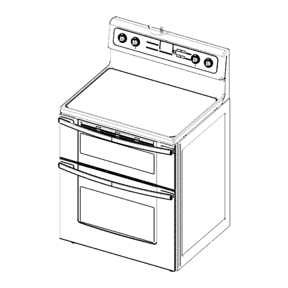
FREESTANDING ELECTRIC RANGE WITH DOUBLEOVENS
INSTRUCTIONSD'INSTALLATION POUR CUISINIERE
ELECTRIQUE AUTOPORTANTE AVEC FOURSDOUBLES
Table of Contents
Table des mati_res
RANGE SAFETY .........................................................................
1
INSTALLATION REQUIREMENTS
............................................
2
Tools and Parts ........................................................................
2
Location Requirements ............................................................
2
Electrical Requirements - U.S.A. Only .....................................
4
Electrical Requirements - Canada Only .................................. 5
INSTALLATION
INSTRUCTIONS ..............................................
6
Unpack Range .........................................................................
6
Adjust Leveling Legs ................................................................
6
Install Anti-Tip Bracket .............................................................
7
Electrical Connection - U.S.A. Only .........................................
8
Verify Anti-Tip Bracket Location ............................................
13
Level Range ...........................................................................
13
Complete Installation .............................................................
13
Moving the Range ..................................................................
14
SI_CURITI_ DE LA CUISINIERE ..............................................
16
EXIGENCES D'INSTALLATION ..............................................
17
Outils et pieces .....................................................................
17
Exigences d'emplacement
...................................................
17
Specifications
electriques - Canada seulement .................. 19
INSTRUCTIONS
D'INSTALLATION .......................................
20
Deballage de la cuisiniere .....................................................
20
Reglage des pieds de nivellement ........................................
20
Installation de la bride antibasculement ............................... 21
Verification de I'emplacement de la
bride antibasculement
..........................................................
22
Reglage de I'aplomb de la cuisiniere .................................... 22
Achever I'installation .............................................................
22
Deplacement de la cuisiniere ................................................
23
RANGE SAFETY
Your safety and the safety of others are very important.
We have provided many important safety messages in this manual and on your appliance. Always read and obey all safety
messages.
This is the safety alert symbol.
This symbol alerts you to potential hazards that can kill or hurt you and others.
All safety messages will follow the safety alert symbol and either the word "DANGER" or "WARNING."
These words mean:
You can be killed or seriously injured if you don't immediately
follow
instructions.
You can be killed or seriously injured if you don't follow
instructions.
All safety messages will tell you what the potential hazard is, tell you how to reduce the chance of injury, and tell you what can
happen if the instructions are not followed.
IMPORTANT:
Save for local electrical inspector's use.
IMPORTANT
:
,&,conserver pour consultation par I'inspecteur local des installations 61ectriques.
W10289536A
Advertisement

Related Manuals for KitchenAid KERS505XSS00


Summary of Contents for KitchenAid KERS505XSS00
- Page 1 INSTALLATIONINSTRUCTIONS FREESTANDING ELECTRIC RANGE WITH DOUBLEOVENS INSTRUCTIONSD'INSTALLATION POUR CUISINIERE ELECTRIQUE AUTOPORTANTE AVEC FOURSDOUBLES Table of Contents Table des mati_res RANGE SAFETY ................. SI_CURITI_ DE LA CUISINIERE ..........INSTALLATION REQUIREMENTS ..........EXIGENCES D'INSTALLATION ..........Tools and Parts ................ Outils et pieces ..............Location Requirements ............
- Page 2 Tip Over Hazard A child or adult can tip the range and be killed. Connect anti-tip bracket to rear range foot. Reconnect the anti-tip bracket, if the range is moved. Failure to follow these instructions can result in death or serious burns to children and adults. INSTALLATION REQUIREMENTS s :xnd Gather the required tools and parts before starting installation.
- Page 3 Cabinet Dimensions Product Dimensions Cabinet opening dimensions shown are for 25" (63.5 cm) countertop depth, 24" (61.0 cm) base cabinet depth and 36" (91.4 cm) countertop height. IMPORTANT: If installing a range hood or microwave hood combination above the range, follow the range hood or microwave hood combination installation instructions dimensional clearances above the cooktop surface.
- Page 4 Ifcodes permit and a separate ground w ire isused, i tis If connecting to a 4-wire system: recommended thataqualified electrical installer determine that This range is manufactured with the ground connected to the theground p athand wire gauge areinaccordance withlocal neutral by a link.
- Page 5 Electrical Shock Hazard Electrically ground range. Failure to do so can result in death, fire, or electrical shock. If codes permit and a separate ground wire is used, it is A time-delay fuse or circuit breaker is recommended. recommended that a qualified electrical installer determine that This range is equipped with a CSA International Certified the ground path is adequate and wire gauge are in accordance Power Cord intended to be plugged into a standard 14-50R...
- Page 6 INSTALLATION INSTRUCTIONS us£Le e/i If range height adjustment is necessary, use a wrench or pliers to loosen the 4 leveling legs. This may be done with the range on its back or with the range supported on 2 legs after the range has been placed back to Excessive Weight Hazard a standing position.
- Page 7 1. Remove the anti-tip bracket that is taped inside the upper Floor Mounting oven with the package containing literature. 2. Determine which mounting method to use: floor or wall. If you have a stone or masonry floor you can use the wall mounting method.
- Page 8 Direct Wire Power Supply Cord Electrical Shock Hazard Electrical Shock Hazard Disconnect power before servicing. Disconnect power before servicing. Use 8 gauge copper or 6 gauge aluminum wire. Use a new 40 amp power supply cord. Electrically ground range. Plug into a grounded outlet. Failure to follow these instructions can result in death, Failure to follow these instructions can result in death, fire, or electrical...
- Page 9 Style 2: Direct wire strain relief • Feed the flexible conduit through the strain relief, allowing enough slack to easily attach wiring to the terminal block. • Use Phillips screwdriver to remove screws and slide cord/conduit plate down and out. •...
- Page 10 5. Use 3/8"nut driver to connect the neutral (white) wire to the 4-wire connection: Power Supply Cord center terminal block post with one of the 10-32 hex nuts. Use this method for: • New branch-circuit installations (1996 NEC) • Mobile homes •...
- Page 11 2. Use 3/8"nut driver to connect the neutral (white) wire to the 4-wire Connection: Direct Wire center terminal block post with one of the 10-32 hex nuts. Use this method for: • New branch-circuit installations (1996 NEC) • Mobile homes •...
- Page 12 Attach terminal lugs to line 1 (black), neutral (white), and line 2 3-wire connection: Direct Wire (red) wires. Loosen (do not remove) the setscrew on the front of the terminal lug and insert exposed wire end through bottom of terminal lugs. Securely tighten setscrew to Use this method only if local codes permit connecting ground XX Ibs-in.
- Page 13 Bare Wire Torque Specifications Attaching terminal lugs to the terminal block - 20 Ibs-in. (2.3 N-m) Place oven rack in oven. Wire Awg Torque Place level on oven rack and check levelness of range, first 8 gauge copper 25 Ibs-in. (2.8 N-m) side to side;...
- Page 14 For direct-wired ranges: Electrical Shock Hazard Tip Over Hazard Disconnect power before servicing. A child or adult can tip the range and be killed. Replace all parts and panels before operating. Connect anti=tip bracket to rear range foot. Failure to do so can result in death or electrical shock.
- Page 16 SECURITE DE LA CUISINIERE Votre securite et celle des autres est tres importante. Nous donnons de nombreux messages de s_curit_ importants dans ce manuel et sur votre appareil m_nager. Assurez-vous toujours lire tous les messages de s_curit_ et de vous y conformer. Ce symbole d'alerte de s_curit_ vous signale les dangers potentiels de d_c_s et de blessures graves &...
- Page 17 EXIGENCESD'INSTALLATION p®ces Rassembler les outils et pieces necessaires avant d'entreprendre IMPORTANT : Observer les dispositions de tousles codes et I'installation. Lire et suivre les instructions fournies avec chacun reglements en vigueur. des outils de la liste ci-dessous. • C'est a I'installateur qu'incombe la responsabilite Outils n_cessaires...
- Page 18 Dimensions du product Dimensions du placard Les dimensions de I'espace d'installation entre les placards sont valides pour I'installation entre des placards de 24" (61 cm) avec plan de travail de 25" (63,5 cm) a hauteur de 36" (91,4 cm). Hauteur du plan de travail 36" (91,4 cm) IMPORTANT •...
- Page 19 • En cas de doute quant & la qualite de la liaison & la terre de la cuisiniere, consulter un electricien qualifi& Puissance nominale de la Intensit_ nominale cuisini_re* sp_cifi_e du cordon d'alimentation et de la protection du circuit 120/240 volts 120/208 volts Electrical Shock Hazard 8,8 &...
- Page 20 INSTRUCTIONS D'INSTALLATION 6@c ge des pi@s de n bme@ 8i un ajustement de la hauteur de la cuisiniere est necessaire, utiliser une cle ou une pince pour desserrer les 4 pieds de nivellement. Ceci dolt _tre effectue alors que la cuisiniere repose sur sa Risque du poids e×cessff partie posterieure ou qu'elle est soutenue par 2 pieds apres Utiliser cleux ou plus de personnes pour d_placer et...
- Page 21 Retirer la bride antibasculement situ6e dans le four superieur Montage au plancher avec I'ensemble de documents d'installation. Determiner la methode de montage & utiliser : au plancher ou au mur. Pour un plancher en pierre ou en briquetage, on peut utiliser la methode de montage au mur.
- Page 22 i _' '_'_ I_S_'_',_ "_ _%_ ,_, f _, 1. Verifier que toutes les pieces sont maintenant installees. 8'il reste une piece, passer en revue les differentes etapes pour 6. 1. S'assurer que la bride antibasculement est installee : decouvrir laquelle aurait ete oubliee. •...
- Page 23 F _=_,,,_t_ _• _ _•_1_" Si le deplacement de la cuisiniere est necessaire pour le nettoyage ou I'entretien : 1. Faire glisser la cuisiniere vers I'avant. 2. Debrancher le cordon d'alimentation electrique. 3. Effectuer le nettoyage ou I'entretien. 4. Brancher le cordon d'alimentation electrique.
- Page 24 W10289536A @2010. 1/lO All rights reserved. Printed in U.S.A. Tous droits reserves. Imprime aux E.-U.
Need help?
Do you have a question about the KERS505XSS00 and is the answer not in the manual?
Questions and answers