Advertisement
Available languages
Available languages
Quick Links
INSTALLATION
AND SERVICE MUST BE PERFORMED BY
A QUAUHED
INSTALLER.
IMPORTANT:
SAVE FOR LOCAL ELECTRICAL INSPECTOR'S USE.
READ AND SAVE THESE INSTRUCTIONS
FOR FUTURE REFERENCE.
mfthe information
in this manuam is not fommowed
e×actmy,
a fire or
e×pmosion
may resumt
causing
prope_y
damage,
personaE iniury
or death.
FOR YOUR SAFETY:
--
Do not store or use gasoline
or other flammable
vapors and liquids in the vicinity
of this or any other
WHAT TO DO [F YOU SMELL GAS:
Do not t_ to might any appmiance.
®
Do not touch any eme_rkam switch; do not use any phone in your building.
*
mmmediatemy cam[your gas supplier from a neighbor's
phone.
Fommow the gas suppmier's instru_ions.
®
If you cannot reach your gas suppmier, camE t he fire depa_ment.
i
mnstammation a nd service must be performed
by a quamified instammer, service agen_
or the gas suppmier.
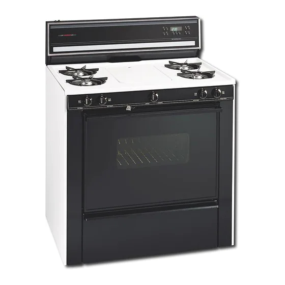
Dimensions
and Cmearance
Provide adequate clearan(e between range
and a@acent combustible surfaces.
TYPICAL
CONTROL
PANEL
X, HEIGHT
HI Profile Control
Panc-,I
45 5/8" I'nin,
LO Profile Control
Panel
40 7/8" Min
25 1/8"
35
_36
....
30" Minimum
A
Minimum to
Minimum to
wall on either
side of range
18"
cabinets on either
above 36" height
.............................................
_,_;_
l
sid6, of range
V
I_ (x::
tx
ix:
tx
tx
tx
t
36"
O" Clearance at rear of
range below cooktop.
Figure I
NOTE: Wiring
diagrams
for these
appliances
are enclosed
in this booklet.
Printed in United States
P/N 318201750
(0410)
Rev C
English - pages 1-9
Espa_ol - p_ginas 10-19
Wiring Diagrams - pages 20-24
Advertisement

Related Manuals for Tappan TGF657BFU4


Summary of Contents for Tappan TGF657BFU4
- Page 1 INSTALLATION AND SERVICE MUST BE PERFORMED BY A QUAUHED INSTALLER. IMPORTANT: SAVE FOR LOCAL ELECTRICAL INSPECTOR'S USE. READ AND SAVE THESE INSTRUCTIONS FOR FUTURE REFERENCE. e×actmy, e×pmosion mfthe information in this manuam is not fommowed a fire or may resumt causing prope_y damage,...
- Page 2 • Before installing the range in area covered with Important Notes to the Installer linoleum or any other synthetic floor covering, Read all instructions contained in these installation make sure the floor covering can withstand heat instructions before installing the range. at least 90°F above room temperature without Remove all packing material before connecting the...
- Page 3 B. Install Y2" flare union adaptor supplied with the 1. Before lnstamming the Range connector, to the Y2" NPT internal thread on pressure Remove shipping materia] regulator. Remove all tape, shipping and packaging materials and the oven rack packaging. Lift up cooktop and remove Gas Connection for Etectdc Ignition Models...
-
Page 4: Top View
Donot usea flameto check for leaks 2 5/8 " 1 7/16" 3A" fromgasconnections. Checking f or leaks withaflame Wall mayresult i n afire or explosion. Disconnect t his rangeandits individualshutoff 11 y2"" _,s",_i, valvefromthegassupply pipingsystem duringany pressure t estingof thatsystem attestpressures greater i ! ii i than14"... - Page 5 B. Surface Burner Valves Conversion C. Readjust the "LOW" Setting Surface Burner Valve Air Shutter 1. Turn control to LITE until burner ignites. 2. Quickly turn knob down to LOWEST SETTING. 3. If burner goes out, readjust valve as described in "Adjust the LOW Setting Surface Burner Valve"...
- Page 6 E. Convert Oven Burner Orifice 1. Open oven door. 2. Locate broiler burner spud and turn down 1. Remove storage drawer if equipped or lower panel approximately 2 Y2turns so that spud is snug against to gain access to oven burner spuds. LP metering pin.
-
Page 7: Check Operation
B) Oven igniter System Do not, under any Self-Clean Models: circumstances, cut, Remove all materials and literature from oven and: remove, or bypass 1. Push the BAKE TEMP button and set the oven the grounding prong, temperature to 300°F. Within 60 seconds tile Grounding bake (lower) burner will ignite. - Page 8 9. When installation is complete, connect the important: See next page for Anti-tip Bracket installation instructions. power cord and set the time of day on the electronic oven control as explained in the Owner's Guide. Model and Serial Number Location Tile model and serial plate is located in the left hand side, underneath the surface cooktop.
-
Page 9: Safety Warning
S. Slide range into place making sure rear legs are 12. important Safety Warning trapped by ends of brackets. Range may need to be This range must be properly secured to the floor by using shifted slightly to one side as it is being pushed back the included anti4ip brackets and screws. - Page 10 LA INSTALAaON Y EL SERVlaO DEBEN SER EFECTUADOS UN INSTALADOR CAUNCADO. IMPORTANTE: GUARDE ESTAS INSTRUCaONES PARA USO DEL INSPECTOR LOCAL DE ELECTRlaDAD° LEA Y GUARDE ESTAS INSTRUCaONES PARA REFERENaA FUTURA. Si todas Jas instrucdones de 6ste manuaJ no son observadas a Ja Jetra, se puede ocurrir incendios...
- Page 11 "'The Federal Standard for Mobile Home Construction Notas importantes para e[ insta[ador and Safety title 24, HUD (Part 280)". Ocuandoestos Lea todas las instrucciones contenidas en este manual estandaresnoseanaplicables: "The Standard for antes de instalar la estufa. Manufactured Home Installation 1982, (Manufactured Saque todo el material usado en el embalaje del Home Sites, Communities and set-ups), ANSI Z225.1, compartimiento del borne antes de conectar el...
- Page 12 Duranteun corte de energ_a e!_ctr!ca se pueden Para controlar el regulador, la presion de entrada debe encender !os quemadores de !a cub!erta con una set de al menos I " mayor que el ajuste de la presion del ceriHa. Acerqueunacerillaencendidaalquemadory m(dtipledelregulador.
- Page 13 E. Verifique si hay fugas. De la vuelta al suministro de gas de la estufa y utilice un dete(tor de fugas Ilquidas en todas las articulaciones y conexiones para verificar si existen fugas. Trasera de la estufa Toma de corrient Niple polarizado de 3 alambres cerrado de...
- Page 14 Junta en forma de 5. Conversi6n de gas propano! bellota Gas natural licuado Aumentar el gas A. Conversi6n el regulador de presi6n Aumentar el tamaFlo de la llama PL Gas No remueva e[ regulador de pres[6n (De fabrica viene Disminuir el gas Disminuir el para usarse con gas tamaFlo de la...
- Page 15 E. Convierta el orificio del quemador D. Obturador de aiuste para e[ aire Proporcione gas al quemador y ajuste el obturador gas en el v6nturi para obtener una llama adecuada. 1. Remueva el caj6n de almacenamiento si el homo le Para gas LP, el obturador de aire se deja generalmente tiene o el panel inferior para acceder alas juntas en abierto, sinembargo.
- Page 16 6. Conexion de la etectdcidad a la F. Conversi6n de la llama del orifido quemador de la alta dntura de parrilla estufa (Modelos autolimpiables soJamente) Requisitos elOctricos Un circuito de caner[as particular conectado correctamente a tierra de 120 voltios, 60 Herz protegidos por un interruptor automOtico de 15 amp.
- Page 17 Dispositivos de encendido de los quemadores Metodo preferido No debe, bajo ninguna superficie circunstanda cortar Para verificar el correcto encendido, presione hacia o retirar la tercera adentro y gire una valvula de quemador superior pata del cable de hastala position "ENCENDIDO"...
- Page 18 Ajuste eJ marco de "LOW" de Ja superdfide 11. Asegurese que el flujo de combusti6n las vaJvuJas para quemadores (yea figura 17) la ventilation del homo y la ventilad6n aire de la parte mas baja del armaz6n de la Tornillo en el vastago estufa no est_n obstruidos.
- Page 19 Deslice la estufa hasta que quede en su lugar 12. Advertencia de seguridad asegurandose de que las patas traseras estan importante atrapadasbajolasplatinasdeanclaje. Puedeser Esta estufa debe ser asegurada al piso usando las necesario balancear la estufa hacia los lados a platinas de anclaie y los tornillos suministrados.
- Page 20 ©VEN THERMOSTAT ]EI,HOSIA F ORlqO JGNil ]GNLTER SW }TCH r'--------h SW ) TCH IGNITER ]GN) TER SW ]TCH e REN _E DEIRECHO BWI iCH ]RASERO )ZOQU_ERDO FRESERO DIZREGJ IO FRENiE I ZOOU IEROO CONNECTOR i..CONECTOR <9 '" (.aD ZZ]L= ZZ]EE OVEN ] GN ) TEA...
- Page 21 OVEN LAMP CONNECTOR CONECTOR IGNITER IGNIFEB SWITCH POWER [NTENC GRIDDLE S_ITCH SWITCH CONNECTOR TRASERO FREN]E INTENC INTENC ]NTENC TRABEDO CONECIOB DERECHO GERECHO PAPILLA FRENTE IZQUIERDO ]ZBUIERDO INTEBBUPFOR ENERGIA CAUTION: LATCH BW[TCH LABEL ALl WIRES PRIOR TO OISCONNECTION _HEN CERROJO SERVICING CONTROIS _IR(NGS ERROR CAN CAUSE INPROPER AND DANGEROUS OPERAIION VERIFY PROPER OPERAIION AFIER SERVICING...
- Page 22 I NE GROUND NEUTRAl ] NEA PUES f [ERRA NEUTRO CHASSIS GROUND CONNECTOR PUESTA TIERRA CONNECTOR CONECTOR /)EL ARMARJO CONECIOR FL UORE CEN I BIARI REOBTATO [DE ARRANQUE FLUOREBCENTE FLUOREBCEN LAMP SW TCH lAST [ N IERRUP BALASrRO FLUORESCENTE F[ UOREC_CENT LAMP OVEN LAMP...
- Page 23 IGNITER [GN]]ER BW]TCH SWITCH SWITCH ]ON[TEA GR]DDLE ]GNI[ER IGNITER PBWER SWITCH swIrcH BWIICII CONNECTOR BAKE CAUTION: CONNECTOR LABEL WIRES PRIOR DIBCONNECT]BN WHEN SERVICING CONTROLS _IRINGB ERROR CAUSE _MPROPER AN© DANGEROUS OPERATION¸ VERIFY PROPER OPERATION AFTER SERVICINB NEUTRAL CONNECTOR WARN ] NG D J BCONNECT POWER BEFORE...
- Page 24 GROUND LINE NEUTRAL CHASSIS POWER CORD/ POWER CORD GROUND CONNECTOR CONNECTOR CLOCK FLUORESCENT FI UORESCENT LAMP SWITCII FLUORESCENT NEUTRAL CONNECTOR IGNI1ER IGNITER SWITCHES II/\RNES5 CONNECTOR SPARK MOE)UIE BURNER IGNITERS OVEN LAMP OVEN LAMP THERMOSTAT TERMINAL BLOCK OVEN BAKE VALVE CONNECIOR OVEN [GNI1ER CAUT[ON:...
Need help?
Do you have a question about the TGF657BFU4 and is the answer not in the manual?
Questions and answers