Table of Contents
Advertisement
Available languages
Available languages
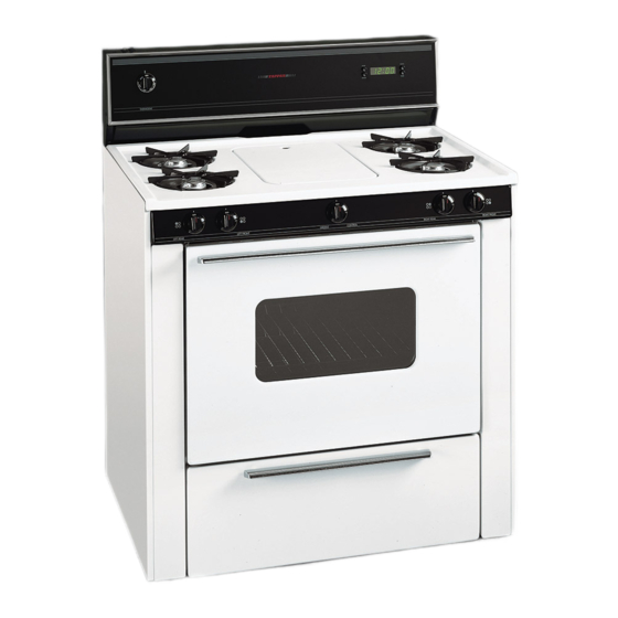
36" GAS RANGE
SELF-CLEANING & NON SELF-CLEANING OVENS
INSTALLATION AND SERVICE MUST BE PERFORMED BY A QUALIFIED INSTALLER
IMPORTANT NOTE TO INSTALLER:
IMPORTANT NOTE TO CONSUMER:
WIRING DIAGRAMS FOR THESE APPLIANCES ARE ENCLOSED IN THIS BOOKLET.
WARNING: If the information in this manual is not followed exactly, a fire or explosion may result
causing property damage, personal injury or death.
– Do not store or use gasoline or other flammable vapors and liquids in the vicinity of this or
any other appliance.
– WHAT TO DO IF YOU SMELL GAS
• Do not try to light any appliance.
• Do not touch any electrical switch; do not use any phone in your building.
• Immediately call your gas supplier from a neighbor's phone. Follow the gas supplier's
instructions.
• If you cannot reach your gas supplier, call the fire department.
– Installation and service must be performed by a qualified installer, an approved service
agency or the gas supplier.
DIMENSIONS AND CLEARANCES
Provide adequate clearance between range
and adjacent combustible surfaces.
25
1
x
45
3
/
"
8
Door open
Printed in Canada
BEFORE YOU BEGIN - READ THESE INSTRUCTIONS
COMPLETELY AND CAREFULLY.
BE SURE TO LEAVE THESE INSTRUCTIONS WITH
THE CONSUMER.
KEEP THESE INSTRUCTIONS WITH YOUR USE AND
CARE BOOK FOR FUTURE REFERENCE.
OBSERVE ALL GOVERNING CODES AND ORDINANCES.
SAVE THESE INSTRUCTIONS FOR LOCAL INSPECTORS.
/
"
8
36"±
1
/
"
8
Typical Control Panel
Hi Profile Control Panel
Lo Profile Control Panel
INSTALLATION INSTRUCTIONS
Minimum to
2"
wall on either
side of range
above 36" height
36"
X. HEIGHT
45 5/8" min.
40 7/8" min.
1
Recycled Paper
36"
30"
Minimum
Minimum to
18"
cabinets on
either side or
range
36 1/4"
between cabinets
P/N 318201700 (9912) Rev. A
0"
clearance
at rear of range
below cooktop.
Advertisement
Table of Contents

Related Manuals for Tappan TGF605WFW5


Summary of Contents for Tappan TGF605WFW5
- Page 1 INSTALLATION INSTRUCTIONS 36" GAS RANGE SELF-CLEANING & NON SELF-CLEANING OVENS INSTALLATION AND SERVICE MUST BE PERFORMED BY A QUALIFIED INSTALLER IMPORTANT NOTE TO INSTALLER: BEFORE YOU BEGIN - READ THESE INSTRUCTIONS COMPLETELY AND CAREFULLY. BE SURE TO LEAVE THESE INSTRUCTIONS WITH THE CONSUMER.
-
Page 2: Important Safety Instructions
IMPORTANT SAFETY INSTRUCTIONS • Do not store or use gazoline or other flammable vapors and liquids near this or any other appliance. Explosions or fires Installation of this range must conform with local codes, or in could result. the absence of local codes, with the National Fuel Gas Code, •... -
Page 3: Normal Installation Steps
NORMAL INSTALLATION STEPS 3-WIRE POLARIZED Figure 1 120V. OUTLET 1. PROVIDE ADEQUATE GAS SUPPLY 3" This range is designed to operate on natural gas at 4" of 25" manifold pressure or on LP gas at 10" of manifold pressure. " ± "... -
Page 4: Check The Igniters
Figure 4 The power cord of this appliance is equipped with a three- prong (grounding) plug which mates with a standard three- " " " ± " prong grounding wall receptacle (Fig. 1) to minimize the WALL possibility of electric shock hazard from this appliance. The customer should MANIFOLD "... -
Page 5: How To Convert The Range For Use With Lp Gas
6. ADJUST THE “LOW” SETTING SURFACE HOW TO CONVERT THE RANGE FOR BURNER VALVE USE WITH LP GAS 1. CONVERT THE PRESSURE REGULATOR Do not remove the Pressure Regulator. CAP SCREW SCREW IN STEM 1. Turn control to LITE until burner ignites. 2. -
Page 6: Air Adjustment Shutter
5. CONVERT OVEN BURNER ORIFICE 3. Lower main top and apply gas to check for proper flame size. Flame should be steady with approximately 1/2" blue FOR LP GAS inner cones and no yellow or orange tips. " INNER CONE FLAME LENGTH PROPER AIR ADJUSTMENT If the air shutter is adjusted so that too much air flows into L.P. -
Page 7: Before You Call For Service
6. CONVERT WAIST HIGH BROILER BURNER ORIFICE FLAME FOR LP GAS (Self-clean models only). SERIAL PLATE NAT. L.P. SPUD IMPORTANT SAFETY WARNING 1. Open oven door. SEE PAGE 8 FOR 2. Locate broiler burner spud and turn down approximately 2-1/2 turns so that spud is snug against LP metering pin. Do ANTI-TIP BRACKET not overtighten. -
Page 8: Important Safety Warning
IMPORTANT SAFETY WARNING For mobile homes, the range must be anchored to the floor as illustrated in Figure “B”. This range must be properly secured to the floor by using the 1. Remove false panel or storage drawer to gain access to included anti-tip brackets and screws. - Page 9 Wiring Diagram Diagrama de la instalación alámbrica (Modelos limpieza manual (Manual Clean Models sin parilla) without Griddle)
- Page 10 Wiring Diagram Diagrama de la instalación alámbrica Manual Clean Models Modelos limpieza manual with Griddle con parilla...
- Page 11 Wiring Diagram Diagrama de la instalación alámbrica Manual Clean Models Modelos Limpieza Manual With Griddle Con Parilla...
- Page 12 Diagrama de la instalación alámbrica Wiring Diagram (Modelos con (Models with horno autolimpiables) Self-cleaning Oven)
- Page 13 Wiring Diagram Diagrama de la instalación alámbrica (Modelos con (Models with horno autolimpiables) self-cleaning oven)
- Page 14 NOTES...
-
Page 15: Dimensiones Y Espacios Libres
INSTRUCCIONNES PARA LA INSTALACIÓN ESTUFA A GAS DE 36” HORNOS AUTOLIMPIABLES Y NO AUTOLIMPIABLES LA INSTALACIÓN Y EL SERVICIO DEBEN SER REALIZADOS POR UN INSTALADOR CALIFICADO. AVISO IMPORTANTE PARA EL INSTALADOR: ANTES DE EMPEZAR - LEA CON ATENCIÓN Y POR COMPLETO TODAS ESTAS INSTRUCCIONES. -
Page 16: Instrucciones De Seguridad Importantes
INSTRUCCIONES SEGURIDAD • No guarde o haga uso de gasolina o otros vaporos y líquidos inflamables acerca de esté o cualquier aparato. Se puede IMPORTANTES resultar en incendios o explosiónes. La instalación de esta estufa debe realizarse en conformidad • Remueva la bandeja de la parrilla y otros utensilios, y todo con los códigos locales o, si éstos no existen, con el National derramamiento antes de usar el ciclo de limpieza a si misma. - Page 17 INSTRUCCIONES PARA UNA Figura 1 TOMA DE CORRIENTE POLARIZADO DE 3 INSTALACIÓN NORMAL ALAMBRES DE 120V. 1. PROVEA UN ADECUADO SUMINISTRO DE GAS 3" Esta estufa ha sido diseñada para utilizar gas natural de 25" 4” de presión múltiple, o para utilizar gas PL de 10” de "...
- Page 18 Figura 4 NO DEBE, BAJO NINGUNA CIRCUNSTANCIA " CORTAR O RETIRAR LA TERCERA PATA (TIERRA) " " ± " PARED DEL CABLE DE ENCENDIDO. MULTIPLE 5. VERIFIQUE LOS DISPOSITIVOS DE ENCENDIDO " " La manipulación de los dispositivos de encendido PARTE SUPE- eléctrico deberán...
- Page 19 COMO CONVERTIR LA COCINA PARA QUE SE 6. AJUSTE EL MARCO DE “LOW” DE LA SUPER- FICIE DE LAS VALVULAS PARA QUEMADORES PUEDA USAR CON GAS PL/PROPANO 1. CONVIERTA EL REGULADOR DE PRESIÓN No remueva el regulador de presión TORNILLO DE CABEZA TORNILLO EN EL VÁSTAGO NAT.
- Page 20 3 . Rabaje la superficie superior y abre el gas para 5. CONVIERTA EL ORIFICIO DEL determinar si el tamaño de la llama es la apropiada. Esta QUEMADOR DEL HORNO PARA debe estar estable formando conos internos azules de 1/ QUE SE PUEDA USAR CON GAS PL 2 pulgada aproximadamente sin extremos amarillos o anaranjados.
-
Page 21: Antes De Llamar Al Servicio Técnico
6. CONVERSION DE LA LLAMA DEL ORIFICIO DEL QUEMADOR DE LA ALTA CINTURA DE LA PARRILLA PARA QUE SE PUEDA USAR CON GAS PL (Modelos autolimpiables solamente) PLACA CON NÚMERO DE SERIE PASADOR JUNTA EN FORMA DE BELLOTA NOTICIA DE SEGURIDAD IMPORTANTE 1 . -
Page 22: Herramientas Requeridas
necesario balancear la estufa hacia los lados a medida ADVERTENCIA DE SEGURIDAD que se desliza hacia atrás para lograr que las platas IMPORTANTE traseras se alinéen con las platinas de anclaje. Para asegurarse de que la estufa está correctamente Esta estufa debe ser asegurada al piso usando las plati- anclada remueva el cajón de almacenamiento o el nas de anclaje y los tornillos suministrados. - Page 23 NOTAS...
- Page 24 NOTAS...
Need help?
Do you have a question about the TGF605WFW5 and is the answer not in the manual?
Questions and answers