Televic Confidea Installation And User Manual
Wired conference system
Hide thumbs
Also See for Confidea:
- Installation and user manual (93 pages) ,
- Installation & user manual (45 pages) ,
- Installation and user manual (69 pages)
Table of Contents
Advertisement
Advertisement
Table of Contents

Related Manuals for Televic Confidea


Summary of Contents for Televic Confidea
- Page 1 Confidea Wired Conference System Installation and User Manual...
-
Page 2: Table Of Contents
Trademarks ........................10 Safety Instructions ......................11 3.1. Important safety instructions ..................11 3.2. Power Connections ....................... 14 Confidea System Information ..................15 Section 2 – System Components ....................16 Table Top Contribution units ..................17 5.1. Introduction ......................... 17 5.1.1. - Page 3 System cables ....................... 80 Software Suite ......................80 Section 3 – System Design......................83 Conference network setup .................... 84 12.1. Interconnecting units ....................84 12.1.1. Confidea wired ......................84 12.1.2. Flushmount panels ......................84 12.1.3. Interpreter unit ......................84 Televic Conference Systems 2011-11-14...
- Page 4 12.2.2. Dual branch Redundancy ....................86 12.3. Connecting the PC to the central unit ................87 12.3.1. Examples of connections ....................88 12.3.2. Confidea coupled (wired + wireless) ................90 12.4. Master slave configuration.................... 91 12.5. Additional equipment for the conference system ............92 12.5.1.
- Page 5 Confidea Wired System Installation and User Manual System Menu......................105 17.1. Diagnostics ......................... 105 17.2. Camera Control......................105 17.3. Control Panel......................105 17.4. Ambient Sound ......................105 17.5. Version........................105 Language Menu ......................105 License Menu ......................105 Section 5 – Appendix ......................... 107 Default Settings ......................
-
Page 7: Section 1 - General Information
Confidea Wired System Installation and User Manual Section 1 – General Information Televic Conference Systems 2011-11-14... -
Page 9: Copyright Statement
Contents are subject to change without prior notice. Copyright© 2011 by Televic Conference NV. All rights reserved. The authors of this manual have made every effort in the preparation of this book to ensure the accuracy of the information. -
Page 10: Trademarks
All terms mentioned in this manual that are known to be trademarks or service marks have been appropriately capitalized. Televic Conference NV cannot attest to the accuracy of this information. Use of a term in this book should not be regarded as affecting the validity of any trademark or service mark. -
Page 11: Safety Instructions
These The Confidea Conference system is state of the art openings must not be blocked or covered. The and has been designed to meet quality. - Page 12 Confidea Wired System Installation and User Manual surfaces may cause the product and cart 15. Lightning combination to overturn. For added protection for this product during a lightning storm, or when it is left unattended and 11. Power Sources unused for long periods of time, unplug it from the This product should be operated only from the type wall outlet.
- Page 13 Confidea Wired System Installation and User Manual 21. Damage Requiring Service 24. Coax Grounding Unplug this product from the wall outlet and refer If an outside cable system is connected to the servicing to qualified service personnel under the apparatus, be sure the cable system is grounded.
-
Page 14: Power Connections
Confidea Wired System Installation and User Manual 3.2. Power Connections Warning: To reduce the risk of fire or electric For permanently connected equipment, a readily shock, do not expose this appliance to accessible disconnect device shall be incorporated in rain or moisture. Do not open the the fixed wiring;... -
Page 15: Confidea System Information
Confidea Wired System Installation and User Manual Confidea System Information This manual describes the wired part of the Confidea range: Confidea CU : Central control unit Confidea –L : Mobile Table top unit Integrated flushmount panels ... -
Page 16: Section 2 - System Components
Confidea Wired System Installation and User Manual Section 2 – System Components Televic Conference Systems 2011-11-14... -
Page 17: Introduction
Voting: Confidea L-DV (Figure 5.4), L-CV (Figure 5.5) Interpretation : Confidea L-DI (Figure 5.6), L-CI (Figure 5.7), L- 2D2I (Figure 5.8) , L-DIV (Figure 5.9), L-CIV (Figure 5.10) 5.1.1. The delegate units. The delegate units feature a built-in loudspeaker, allowing the participant to directly hear all audio information, e.g. -
Page 18: Functionality Overview
5.3. Controls and 10. PRIOR button: indicators Short press : temporarily deactivates the microphone of all active units. The Confidea units have the following features: Long press : permanently deactivates the microphone of all active units. Microphone connector: 11. Next button: Connection of a microphone to the wireless unit. - Page 19 Confidea Wired System Installation and User Manual Figure 5.1: Confidea L-DD Figure 5.2: Confidea L-CD Televic Conference Systems 2011-11-14...
- Page 20 Confidea Wired System Installation and User Manual Figure 5.3: Confidea L-2D2D Figure 5.4: Confidea L-DV Televic Conference Systems 2011-11-14...
- Page 21 Confidea Wired System Installation and User Manual Figure 5.5: Confidea L-CV Figure 5.6: Confidea L-DI Televic Conference Systems 2011-11-14...
- Page 22 Confidea Wired System Installation and User Manual Figure 5.7: Confidea L-CI Figure 5.8: Confidea L-2D2I Televic Conference Systems 2011-11-14...
- Page 23 Confidea Wired System Installation and User Manual Figure 5.9: Confidea L-DIV Figure 5.10: Confidea L-CIV Televic Conference Systems 2011-11-14...
- Page 24 Confidea Wired System Installation and User Manual Figure 5.11: RJ45 connections Televic Conference Systems 2011-11-14...
-
Page 25: Installation
Confidea Wired System Installation and User Manual 5.4. Installation 5.5. Maintenance In order to use the Confidea units, the microphone 5.5.1. General need to be installed. For instructions, see the microphone installation Caution: Do not put any objects on top of the Make sure that the units are not positioned too close units. -
Page 26: Microphones
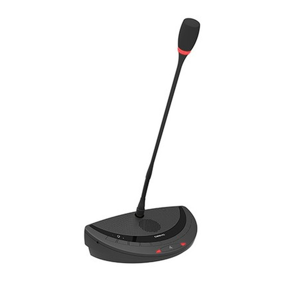
5.6.3. Microphone connector 5.6. Microphones Figure 5.4: Connector pin layout (bottom view) 5.6.1. Introduction The Confidea-MIC38SL (38 cm) pluggable microphone is used with the different delegate- and chairman units. This microphone has a unidirectional response for optimum performance even in noisy conditions, and has a very low susceptibility to RF- interference from mobile phones. -
Page 27: Operation
For mounting, plug and fasten the microphone into the unit. Caution: Do not force the microphone screw thread while mounting the microphone on the unit. This can cause permanent damage to the microphone and receptacle connector on the Confidea unit. Televic Conference Systems 2011-11-14... -
Page 28: Flushmount Contribution Units
Confidea Wired System Installation and User Manual Volume buttons: Flushmount Change the volume level of the headphones. Contribution units Voting buttons: Each voting button has a blue LED indicator. Information display: 6.1. Introduction Indication of volume and channel information. Channel selection buttons:... - Page 29 Confidea Wired System Installation and User Manual Figure 6.1 : FD/M Figure 6.2 :FC/M Televic Conference Systems 2011-11-14...
- Page 30 Confidea Wired System Installation and User Manual Figure 6.3 : FD/MV5B Figure 6.4 : FC/MV5B Televic Conference Systems 2011-11-14...
- Page 31 Confidea Wired System Installation and User Manual Figure 6.5 : FD/MV5CS Figure 6.6 : FC/MV5CS Televic Conference Systems 2011-11-14...
- Page 32 Confidea Wired System Installation and User Manual Figure 6.7 : FD/MV5BCS Figure 6.8 : FC/MV5BCS Televic Conference Systems 2011-11-14...
-
Page 33: Installation
Confidea Wired System Installation and User Manual 6.3. Installation The integrated panels are flush mount panels and need to be integrated in conference furniture. The cut-out of the different models can be found below. FD/M and FC/M Error! Not a valid bookmark self-reference. - Page 34 Confidea Wired System Installation and User Manual Figure 6.9 : Dimensions and cut-out FD/M and FC/M Televic Conference Systems 2011-11-14...
- Page 35 Confidea Wired System Installation and User Manual Figure 6.10 : Dimensions and cut-out FD/MV5B and FC/MV5B Televic Conference Systems 2011-11-14...
- Page 36 Confidea Wired System Installation and User Manual Figure 6.11 : Dimensions and cut-out FD/MV5CS and FC/MV5CS Televic Conference Systems 2011-11-14...
- Page 37 Confidea Wired System Installation and User Manual Figure 6.12 : Dimensions and cut-out FD/MV5BCS and FC/MV5BCS Televic Conference Systems 2011-11-14...
-
Page 38: Maintenance
Confidea Wired System Installation and User Manual 6.4. Maintenance 6.4.1. General Caution: Do not put any objects on top of the units. Object falling through the holes of the unit can cause damage. Caution: Do not install the units in a location near heat sources as radiators, air ducts. -
Page 39: Interpreter Desk
Confidea Wired System Installation and User Manual Headphone connection, 3,5mm jack Interpreter desk Loudspeaker Badge reader 7.1. Introduction Badge LED In cases where interpretation is required one or A channel button several interpreter desks will be required in the B channel button system. - Page 40 Confidea Wired System Installation and User Manual Televic Conference Systems 2011-11-14...
-
Page 41: Maintenance
Confidea Wired System Installation and User Manual 7.3. Maintenance 7.3.1. General Caution: Do not put any objects on top of the units. Object falling through the holes of the unit can cause damage. Caution: Do not install the units in a location near heat sources as radiators, air ducts. -
Page 42: Central Control Unit
The Confidea CU is the heart of the system. It controls all delegate units and can interconnect to 12. RJ-45 shielded connectors (SLAVE IN) for a... - Page 43 Confidea Wired System Installation and User Manual 24. Headphone connection, 3.5 mm jack socket. The audio signal of the headphone connection is directly associated with the AUX OUT 6 port. Every change in the configuration of the AUX OUT 6 port will be noticeable on the headphone...
- Page 44 The CONFIDEA CU’s menu control allows to: An analog output panel ( AOP) can also be connected to the CONFIDEA CU. The purpose of the analog set the conference system to one of the 10 output panel is to provide the system with additional different operating modes (note however analog outputs.
-
Page 45: Additional Licenses
Confidea Wired System Installation and User Manual 8.5.2. XLR IN Connection 8.3. Additional Licenses The AUX IN1, 2 connections on the central unit have The central unit has a standard license to handle 4 a XLR 3 Female connector. So a cable with XLR 3 interpreter channels. -
Page 46: Sub D 15 Out Connection
Confidea Wired System Installation and User Manual 8.5.4. Sub D 15 OUT connection jack) Pin 7 Control out The Sub D 15 OUT connector on the central unit can output 6 channels (FL + 5 channels). Pin 8 Control in (max 5V) - Page 47 Confidea Wired System Installation and User Manual Flow control: None In case there is a lack of available serial ports on the PC a USB to serial converter can be used. This is the configuration of a standard null modem cable.
-
Page 48: Repeater For The System
The repeater box has two ports, the IN and OUT port. The RJ-45 OUT connector (1) should be connect to a delegate unit and the Confidea central unit should be connected to the RJ-45 IN connector (2) of the repeater. -
Page 49: Menu Structure
Confidea Wired System Installation and User Manual 8.7. Menu structure The menu structure on the next pages can be used as a quick reference guide to configure the conference systems. In each menu structure the following information is given: ... - Page 50 Confidea Wired System Installation and User Manual Main menu Volume = TCS 2500-D ENTER 1 Conference EXIT DOWN TCS 2500-D 2 Interpretation EXIT DOWN TCS 2500-D 3 Aux-In/Out EXIT DOWN TCS 2500-D 4 System EXIT DOWN TCS 2500-D 5 * Language...
- Page 51 Confidea Wired System Installation and User Manual Conference menu (1 of 7) Televic Conference Systems 2011-11-14...
- Page 52 Confidea Wired System Installation and User Manual Conference menu (2 of 7) Televic Conference Systems 2011-11-14...
- Page 53 Confidea Wired System Installation and User Manual Conference menu (3 of 7) Televic Conference Systems 2011-11-14...
- Page 54 Confidea Wired System Installation and User Manual Conference menu (4 of 7) Televic Conference Systems 2011-11-14...
- Page 55 Confidea Wired System Installation and User Manual Conference menu (5 of 7) Televic Conference Systems 2011-11-14...
- Page 56 Confidea Wired System Installation and User Manual Conference menu (6 of 7) Televic Conference Systems 2011-11-14...
- Page 57 Confidea Wired System Installation and User Manual Conference menu (7 of 7) Televic Conference Systems 2011-11-14...
- Page 58 Confidea Wired System Installation and User Manual Interpreter menu (1 of 5) Televic Conference Systems 2011-11-14...
- Page 59 Confidea Wired System Installation and User Manual Interpreter menu (2 of 5) Televic Conference Systems 2011-11-14...
- Page 60 Confidea Wired System Installation and User Manual Interpreter menu (3 of 5) Televic Conference Systems 2011-11-14...
- Page 61 Confidea Wired System Installation and User Manual Interpreter menu (4 of 5) Televic Conference Systems 2011-11-14...
- Page 62 Confidea Wired System Installation and User Manual Interpreter menu (5 of 5) Televic Conference Systems 2011-11-14...
- Page 63 Confidea Wired System Installation and User Manual Aux IN/OUT menu (1 of 8) Televic Conference Systems 2011-11-14...
- Page 64 Confidea Wired System Installation and User Manual Aux IN/OUT menu (2 of 8) Televic Conference Systems 2011-11-14...
- Page 65 Confidea Wired System Installation and User Manual Aux IN/OUT menu (3 of 8) Televic Conference Systems 2011-11-14...
- Page 66 Confidea Wired System Installation and User Manual Aux IN/OUT menu (4 of 8) Televic Conference Systems 2011-11-14...
- Page 67 Confidea Wired System Installation and User Manual Aux IN/OUT menu (5 of 8) Televic Conference Systems 2011-11-14...
- Page 68 Confidea Wired System Installation and User Manual Aux IN/OUT menu (6 of 8) Televic Conference Systems 2011-11-14...
- Page 69 Confidea Wired System Installation and User Manual Aux IN/OUT menu (7 of 8) Televic Conference Systems 2011-11-14...
- Page 70 Confidea Wired System Installation and User Manual Aux IN/OUT menu (8 of 8) Televic Conference Systems 2011-11-14...
- Page 71 Confidea Wired System Installation and User Manual System menu (1 of 2) Televic Conference Systems 2011-11-14...
- Page 72 Confidea Wired System Installation and User Manual System menu (2 of 2) Televic Conference Systems 2011-11-14...
- Page 73 Confidea Wired System Installation and User Manual Language menu (1 of 1) Televic Conference Systems 2011-11-14...
- Page 74 Confidea Wired System Installation and User Manual License menu (1 of 1) Televic Conference Systems 2011-11-14...
-
Page 75: Analog Output Panel
Confidea Wired System Installation and User Manual Analog Output Panel 9.1. Introduction The AOP is an optional analog output to be used if the external outputs on the central unit are not sufficient. The outputs are often used to connect language distribution or recording system. - Page 76 Confidea Wired System Installation and User Manual Televic Conference Systems 2011-11-14...
-
Page 77: Installation
Confidea Wired System Installation and User Manual 9.3. Installation 9.4. Configuration The IN port of the AOP unit is connected on the The channels on the output can be configured. Below DATA OUT port of the central unit with a shielded Cat a description of the possibilities and how to make the 5 patch cable. -
Page 79: Remote Control
Confidea Wired System Installation and User Manual 9.5. Remote Control The unit has a voltage free contact that is closed whenever a microphone is active. When no microphone is active the contact is open. Please see below for the pin assignment of the Phoenix connector. -
Page 80: System Cables
11. Software Suite For more advanced control and visualization The system cables used as connection between the purposes the Televic Software suite can be central unit and the contribution equipment, and from unit to unit is Cat5e AWG 24 FTP cables with installed on one or several PC’s. - Page 81 Confidea Wired System Installation and User Manual Speaker and Speech time visualization Voting result visualization To output a synoptic overview, speakers list, speech time the license S-MM and S-DM are also required. When used to display voting results all the licenses...
-
Page 83: Section 3 - System Design
Confidea Wired System Installation and User Manual Section 3 – System Design Televic Conference Systems 2011-11-14... -
Page 84: Conference Network Setup
This makes it convenient recognize the IN port of the unit and connect the grey plug of the system cable. Different types of Confidea contributor units can be mixed in one branch (L-CV,L-DIV,L-DI,…) Televic Conference Systems... -
Page 85: Connection To The Central Unit
12.2.1. General setup After interconnection of several contributor units, the branch of units needs to be connected to one of the digital port of the Confidea CU: Confidea CU has 6 digital branches. Each branch supports up to 20 units (6 *20 = 120 units) ... -
Page 86: Dual Branch Redundancy
Integrated flushmount or Closing the loop by returning from the last unit in a interpreter units branch to a port of the Confidea CU redundancy is added to the system. Televic Conference Systems 2011-11-14... -
Page 87: Connecting The Pc To The Central Unit
Confidea Wired System Installation and User Manual The port on the back of the Confidea central unit 12.3. Connecting the PC to labeled COM 3 is the port associated with the the central unit microphone management system (TMS2500). Note that the software versions will be checked at The PC software consists out of two different parts. -
Page 88: Examples Of Connections
Confidea Wired System Installation and User Manual 12.4. Examples of connections Televic Conference Systems 2011-11-14... - Page 89 Confidea Wired System Installation and User Manual Televic Conference Systems 2011-11-14...
-
Page 90: Confidea Coupled (Wired + Wireless)
Confidea Wired System Installation and User Manual 12.5. Confidea hybrid system (wired + wireless) For more information how to connect the Confidea CU with Confidea wireless/ wired see the manual about Confidea wireless. Televic Conference Systems 2011-11-14... -
Page 91: Master Slave Configuration
Connect the MASTER OUT port of the Master The menu of a slave central unit cannot be accessed. Confidea central unit to the SLAVE IN port of the This means that all settings need to be done on the next Confidea central unit. -
Page 92: Additional Equipment For The Conference System
By adding an AOP2500 unit to the system the floor plus 8 interpreter channels can be outputted. The Via the XLR-3F socket of the Confidea central unit, first interpreter channel can be configured. The other external audio sources which output a balanced... -
Page 93: Section 4 - The Menu Explained
Confidea Wired System Installation and User Manual Section 4 – The Menu explained Televic Conference Systems 2011-11-14... -
Page 95: Conference Menu
Confidea Wired System Installation and User Manual The add unit option can be used in case you already 13. Conference menu have a room setup and want to add some units. Activating this option, all units unknown to the A number of default settings are loaded into the system will start to blink. -
Page 96: Microphone Limit
Confidea Wired System Installation and User Manual Selecting a certain conference mode will strongly FIFO: Enables one microphone to be active at all influence the way a meeting is held: times. Activation of a new microphone will deactivate the current active microphone unit. -
Page 97: Microphones
Confidea Wired System Installation and User Manual This option adjusts the limiter gain option of the 13.5. Microphones microphones by setting the desired offset value in The Microphones menu item alters the audio This setting determines the reach of the settings of the conference unit’s microphone. -
Page 98: Reset
Confidea Wired System Installation and User Manual 13.7. Reset The Reset menu option initiates a reset of the microphone system. The interpretation units are not affected by this reset command. 13.8. Options This menu contains three items, being Test Tone, Test units and Light Ring. -
Page 99: Interpretation Menu
Confidea Wired System Installation and User Manual configurations in total. Not saving the configuration 14. Interpretation menu brings the interpreter system in the same state as it was before you entered the configuration menu. 14.1. Configuration Load Configuration A previously saved interpreter configuration can be The configuration menu allows making a new loaded. -
Page 100: Initialization
Confidea Wired System Installation and User Manual startup of the system. Remember the B Channel can The auto-floor indication led is activated on these interpreter desks. be changed on the interpreter desk. The auto-floor only concern the interpreter side of... -
Page 101: Reset
A total of 28 different booths can be configured on headsets. The interpreters are notified of this mixed the Confidea CU. Within each booth it is possible to audio signal by the flashing of the microphone led have 8 interpreter desks. - Page 102 Confidea Wired System Installation and User Manual Any interpreter microphone in another booth can override the current active microphone and become the active interpreter. The interpreter microphone set to non-active can become active for this translation by reactivating his microphone button.
-
Page 103: Auxiliary Menu
IN 1 and AUX IN 2. The two inputs are both XLR-3F connectors. The Confidea CU has 6 auxiliary outputs. The AUX There are a few settings that can be adjusted: OUT 1 has a fixed output of the Floor and can’t be changed. -
Page 104: External Equalizer
Confidea Wired System Installation and User Manual Figure 15.1: External Equalizers OFF Room 1 AUX OUT 1 AUX IN1 T 3.15 A L ( 230 V) T 7 A L ( 115 V) CO M 1 AUX OUT / CONTRO L... -
Page 105: System Menu
Confidea Wired System Installation and User Manual 16. System Menu 16.5. Version 16.1. Diagnostics This menu option show the current version of the Confidea CU. This menu shows an overview of the central unit 17. Language Menu ports. It can be used to check if communication errors on the ports of the CU. -
Page 107: Section 5 - Appendix
Confidea Wired System Installation and User Manual Section 5 – Appendix Televic Conference Systems 2011-11-14... -
Page 109: Default Settings
Confidea System Installation and User Manual 19. Default Settings Main Menu Item Sub Menu Item Item Default Value Conference Operating Mode Operating Mode Direct Access Conference Microphone Limit Microphone Limit Max. Limit = 4 Conference Loudspeaker Volume Conference Loudspeaker Bass... - Page 110 Confidea System Installation and User Manual Aux-In/Out Aux Out 3 Status Aux-In/Out Aux Out 4 Volume Aux-In/Out Aux Out 4 Channel Aux-In/Out Aux Out 4 Status Aux-In/Out Aux Out 5 Volume Aux-In/Out Aux Out 5 Channel Aux-In/Out Aux Out 5...
- Page 111 Confidea System Installation and User Manual System Ambient Sound Aux In Switch off = NO Language Choose Language Language English Televic Conference Systems 2011-11-14...
-
Page 112: Camera Control Protocol
CRC = 16 bit sum of the ASCII characters between commands are described below. STX and CRC Connection between the Confidea CU and the Notation to explain the messages sent. All separate control system is established with a RS232 entities in a message are represented between curly connection. -
Page 113: Examples
Confidea System Installation and User Manual First microphone has been activated and the camera When no microphones are active, then the following control should become active. synchronization will be received: %S00000113 When the camera control system should reset itself {‘%’}{‘1’}{‘R’}{‘00’}{{CRC (4)}... -
Page 114: Control Panel Protocol
21.1. Communication CRC = 16 bit sum of the ASCII characters between STX and CRC The Confidea system can be controlled by control We will adopt a certain notati on to explain the systems such as AMX, Crestron, … The commands messages sent. - Page 115 Confidea System Installation and User Manual The Commands sent by the central unit and With Request Group 2 receivedby the control panel: With Request No Group 3 Clear A microphone is activated: Direct Access Group 4 {‘%’}{‘1’}{‘L’}{Microphone number (4)} {CRC (4)}...
-
Page 116: Examples
Confidea System Installation and User Manual The default volume setting can be set by sending the {‘%’}{‘1’}{‘x’}{‘o’}{‘009’}{CRC (4)} following command to the central unit: 16. Toggle the status for Auxiliary Output port 6 %1X060606060221 {‘%’}{‘1’}{‘x’}{‘o’}{‘010’}{CRC (4)} Any other commands sent over the serial channel from the central unit to the control panel should be ignored.
Need help?
Do you have a question about the Confidea and is the answer not in the manual?
Questions and answers