Table of Contents
Advertisement
Advertisement
Table of Contents

Related Manuals for TC Electronic DB4 MKII


Summary of Contents for TC Electronic DB4 MKII
- Page 1 Operation manual English DB4/DB8...
-
Page 3: Table Of Contents
DSP and I/O Expansion cards ....... 9 DSP & Card Connection ........10 Remote CPU ............13 TC ICON ............. 14 DB4/DB8 network & Updating Software ....15 DB8/DB4 Network ..........19 Savvy WI-fI networking for DB8/DB4....20 Basic Operation ........... 21 Library - Recall ............ -
Page 4: Important Safety Instructions
ImpOrTanT safeTy InsTruCTIOns The lightning flash with an arrowhead symbol within an The exclamation point within an equilateral triangle is equilateral triangle, is intended to alert the user to the intended to alert the user to the presence of important presence of uninsulated “dangerous voltage” within the operating and maintenance (servicing) instructions in product’s enclosure that may be of sufficient magnitude... -
Page 5: Introduction
We are confident you will value your new possibilities. be it local or remotely located machines. Software and Manual for DB8 and DB4 Software updates for both machines are always released simultaneously, and the two machines share the same manual. -
Page 6: Getting Started
GeTTInG sTarTeD This is an illustration of how to connect a standard DB8/DB4 as it comes with one Mainframe and one TC Icon software Editor. We recommend reading through the entire Hardware & Installation section before operating. Connections Install the TC Icon Software Editor 8 x XLR FOR DIGITAL I/O Follow the intallation instructions. • Open the TC Icon Software Editor and the following screen will appear. 25PIN DSUB TO XLR... -
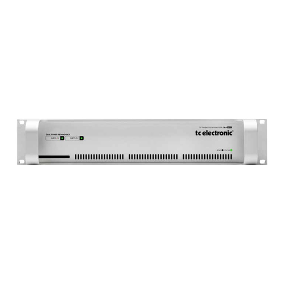
Page 7: Mainframe - Front
DUAL POWER REDUNDANCY SUPPLY 1 SUPPLY 2 RESET STATUS Power Supply 1 & Power Supply 2 LEDs DB8/DB4 features two fully independant power supplies. Each power supply has its own status LED. - For each power supply a green LED indicates that external power is connected and the power supply is fully functioning. - A red LED indicates a problem. Either there is no external power connected or there is a problem at certain checkpoints in the relevant power supply. -
Page 8: Main Frame - Rear
Do NOT mount an ADA 24/96 card in any of the and stability accepts 100-230V AC. 50/60Hz. card slots. DB4/DB8 MKII does NOT support the Connect to two independent power sources to be safe in ADA 24/96 card and the card will be damaged if case of a fuse blow. -
Page 9: Dsp And I/O Expansion Cards
For DSP cards all jumpers must be set to off (up position) Mainframe or placed in an anti-static shielded bag. Mounting Modules Before mounting modules in your DB8/DB4, unplug the mains power cable. Remove the dummy-panel or original module from the slot where you want to install the module. The module should then be removed from the shielded bag... -
Page 10: Dsp & Card Connection
Dsp & CarD COnneCTIOn SDI cards The SDI card for DB4/DB8 supports all commonly used SD and HD formats. While de-embedding and embedding 8 channels of audio (48 kHz, 24 bit), selectable from the four SDI Groups in chunks of four audio channels, it passes the video side untouched. Processing may be inserted on any two of the four SDI Groups, and re-embedding may take place on any two groups. - Page 11 Dsp & CarD COnneCTIOn AES3 COAX - DSP Caution! The servicing instructions are for use by qualified personnel only. To reduce the risk of electric shock do not perform any servicing other than that in the operation instructions unless you are qualified to do so. Introduction Hardwire Bypass at power off The optional AES-3 Coax card with 8 BNC connections...
- Page 12 Cable type is twisted pair (12 pairs) with common screen. synced via Word Clock, termination on the last device of Recommended impedance: 110 Ohm. the chain is necessary. As the DB8/DB4 is expected to be the last unit in such a One end is equipped with an AES/EBU 25 pin D-Sub chain (or the only), the factory default setting on the DSP connector, the other end is equipped with four male XLR’s card is: TERMINATED (75 Om).
-
Page 13: Remote Cpu
Cpu The following section describes the TC ICON hardware remote control. Up to 8 mainframes can be controlled via the TC ICON hardware remote but DB8/DB4 units are most often controlled via PC or Mac using the free TC Icon Software Editor. When using up to four instances of the TC Icon Software Editor; 32 frames can be controlled simultaneously. Please find descriptions of both in the following manual sections. Remote CPU front panel Power Key Switches power On/Off. Green LED indicates power on state. Remote CPU rear panel... -
Page 14: Tc Icon
TC ICOn TC Icon Front TC Icon Rear 198 mm Screen TC Connection Cable. The TC Icon screen is a touch-sensitive capacitive screen. Use the special TC Icon cable supplied with the unit ONLY! Touch calibration as well as brightness and colors can be No other cables can be used. The 7.5 meters (22 feet) adjusted/selected in the TC Icon Setup menu. - Page 15 Db4/Db8 mKII sOfTware Keeping your software updated DB4/DB8 is a constantly evolving platform and updating software is a standard procedure to keep the system up-to-date. Depeding on your setup, software-updates can be done in a couple of different ways described on the following pages. Software types There are three types of software in a DB4/DB8 mainframe, one for the TC Icon Remote CPU MKII and then the TC Icon Software Editor for PC and Mac, that can be used instead of a TC Icon (hardware version) • F rame software • N et (Ethernet) software • D SP software...
- Page 16 Db4/Db8 mKII sOfTware Updating Remote CPU MKII software Update Remote CPU 2 TC ICON MKII LAN 2 REMOTE CPU MKII Standard Ethernet cable INTERNET Remote CPU MKII software is updated directly via the If you see a message “Download from web failed”, go to the internet. Setup/Net page and ensure that it says: “Connected. TC Website Available”, under Internet DHCP - Connect Remote CPU MKII LAN 2 to your internet router Connection (LAN 2) using a standard ethernet cable...
- Page 17 Update Mainframe SW upDaTInG Db4/Db8 mKII sOfTware Updating Mainframe 6000 MKII software TC ICON EDITOR on PC OR MAC DB4/DB8 MKII TV TRANSMISSION PROCESSOR /DB-8 DUAL POWER REDUNDANCY SUPPLY 1 SUPPLY 2 X-Coupled Ethernet cable RESET STATUS The Icon Editor shows the update status via a progress bar.
- Page 18 Db4/Db8 mKII sOfTware Advanced setup - Central Server setup for software for update and preset handling “TC NETWORK” (Static IP) - STUDIO A “TC NETWORK” (Static IP) - STUDIO B DB8/DB4 MKII TV TRANSMISSION PROCESSOR /DB-8 8 x XLR FOR DIGITAl I/O...
- Page 19 Db4/Db8 mKII sOfTware Central Server (MotherShip) setup Updating your software: This is a typical setup in larger studio facilities with several • Download the software from: rooms, where you place software updates and e.g. a preset http://www.tcelectronic.com/system6000support.asp vault on a central server/computer in a shared folder.
- Page 20 In the examples below we use the following folder names: “S6Kpresets” - for preset banks “S6Kautomation” - for automation presets Presets Presets are handled as entire Banks and you load/save an entire bank between the server and your local DB4/DB8 MKII Mainframe. * The exact path to the folder on the server must be entered Example: Path to folder with automation presets - Mac in the File Folder field on the Library bank page. Example: Path to folder with presets banks - PC...
- Page 21 neTwOrK basICs Setting Subnet Mask & TCP/IP on a PC Subnet Mask & TCP/IP addresses To find the TCP/IP address and the Subnet Mask settings The Subnet Mask is a number that defines a group of on your computer running Windows: computers (or Icons/Mainframes) connected to the network. All units in the group must have the same Subnet Mask. Example - Windows XP The DB8 Subnet Mask is by default 255.255.255.0 Go to Control Panel, Network Connections, Internet Protocol (TCP/IP) The TCP/IP address is unique to each unit connected in the network.
- Page 22 neTwOrK basICs Shared folders PC - basics Now go to the folder you want to share • Right-click on the folder and select properties When sharing a folder on Windows XP/VISTA/WIN7 you • Select Sharing have to make sure that the user of the TC Icon Remote • Mark “Share this folder” CPU MKII has rights to access read/write in the share • Type in the name ”iconupdate” as share name folder. • Mark “Maximum allowed” in User Limit The default user on your hardware ICON is already setup: User name : ICON Password...
- Page 23 neTwOrK basICs Windows 7 note Shared folders Mac - basics For succesfully sharing a folder on Win7 x86/x64 you have On Mac computers shared folders are setup in System to setup sharing rights for the folder(any share) on the Preferences - Shared. machine. - Open Network and Sharing Center by clicking the Start button , clicking Control Panel, clicking Network and Internet, and then clicking Network and Sharing Center.
- Page 24 Updating from a Central Server - The software is downloaded, placed in a shared folder on a central server and updated from there. TC Electronic does NOT have access to any files or information on devices connected to LAN2. Updating directly from the Internet • First of all you should check whether your Icon software is up-to-date or not. Press Update Version Info on the...
-
Page 25: Basic Operation
Accessing a Mainframe Generally : • Press the top-tabs to do primary selections First time you connect the Mainframe to the PC with • Press the side-tabs or elements to do secondary installed PC editor and network adapter: selections. • Power up your computer and your DB8/DB4. Fig 1 • Start the Software editor and the following page appears: Via the “overall” Select & Setup pages you access overall settings and choices like: • Press Assign • Selection of which mainframe to operate • All connected DB8/DB4 mainframes will be detected and • Enable devices to network... - Page 26 Group Selector Fine Adjust Operating Levels The Library-Recall page illustrated in Fig.3 leads to explanation of the “operating levels” in the DB8/DB4. We differentiate between 2 levels of presets: Scene and Engine levels. • SCENE This is the most extensive selection you can make. It includes all four Engine algorithms as well as physical Fader at right side and virtual Engine Routings.
-
Page 27: Library - Recall
Recalling a Scene, Routing or Engine preset • Press the RECALL tab to select the Recall page. • Now select the level of: Scene, Routing or Engine 1-4. On the Library Recall page the following banks are • Select which bank you wish to recall from: Factory or available for recall operations: User. If a DB8/DB4 formatted PCMCIA card is inserted in the Mainframe card-banks will be available and displayed Scene below the User banks. Gives access to the following preset banks: • Select presets pressing: Bank, Decade(tens) and preset • Factory... -
Page 28: Library - Store
lIbrary - sTOre Operation Level Tabs Bank Selectors Library, Frame and Engine selectors Function Select Tabs Decade selector (“tens”) Preset location selector (“ones”) Fader Group Selector Library Store values.The preset is not stored when the keyboard’s Enter key is pressed. Only the name is entered. For storing operations the following banks are available. -
Page 29: Library - Bank
Press to activate copy function between the selected Banks. Rename Press to rename selected bank via the Naming pop-up display. Delete Press to clear the selected Bank. You will be asked to confirm your choice to avoid unintended deletion. Using PCMCIA cards To use a PCMCIA card with DB8-DB4 the card must be properly formatted. This is done from the Frame/System/ Card page. -
Page 30: Library - Delete
lIbrary - DeleTe Library, Frame and Engine selectors Function Select Tabs Fader Group Selector Library - Delete For convenience it is possible to “clean up” the User banks by deleting individual presets. Deleting a Preset • Select Delete (side tab) and select level by pressing Scene or Engine. -
Page 31: Routing - Page
I/O channels in the loaded algorithm. Mainframe. All routings of physical Inputs/Outputs as well as internal routing between Engines is setup here. The understanding of this page is therefore essential to Frame - E1 to E4/E2 (DB8/DB4) operating the DB8/DB4. To access the Routing Page: • Press Frame (upper tab) • Press Routing (side tab) -
Page 32: Frame - System - Main
frame - sysTem - maIn State Detected Sample Rate This is a read-only parameter indicating the actual incoming Sample Rate. The tolerance of this detection is +/- 10Hz. Example: An incoming Sample Rate of 44.056kHz will be detected as approx. 44.06kHz and the system indicates the Locked Clock Rate 44.100kHz. -
Page 33: Frame - System -Main -Gpi
- sysTem -maIn -GpI DB4 and DB8 GPI Specification DB4 and DB8 offers a GPI input for remote switching between Scenes (all Engine Presets plus Routing). The input can be used for daily operation, or for backup and redundancy purposes. It allows change between 2, 4 or 8 presets using just one connection. GPI functionality includes two flexible modes (“3 presets” and “7 presets”) where normal editing of presets is allowed unless the GPI input is moved away from its idle state. These modes are typically be used for putting the machine into a defined state, for instance for backup or emmergency announcements overruling normal operation. -
Page 34: Frame - System -Main -Gpi
frame - sysTem -maIn -GpI Installation Selection between up to 8 presets is achieved by feeding the processor a DC voltage to the 1/4” jack input labeled “Pedal”. The input voltage is compared against voltage windows that correspond to certain presets. Between the valid voltage windows, invalid windows have been inserted to protect against erratic operation. The processor constantly monitors the GPI input, and only if several consecutive measurements point to the same, valid voltage window, a recall is performed. The voltage windows chosen enable easy “binary relay encoding” as shown in fig. 1. If long cable runs are required, HF decoupling using a ceramic capacitor across the Tip and Sleeve terminals inside the jack plug may be indicated. - Page 35 frame - sysTem -maIn -GpI GPI Technical specifications Inside the processor, a 10kohm resistor connects the Tip terminal to a +5V power supply. When nothing is connected to the GPI input, the input voltage therefore is +5V. Resistors can be used to pull down the voltage as suggested in Fig 1. In Table 1, voltages outside the limits mentioned are to be considered invalid. No action is taken if invalid measurements are made. GPI recall action resumes when a stable, valid measurement again is detected. Mode Preset No Target / Vs...
-
Page 36: Frame - System - Main - Midi
frame - sysTem - maIn - mIDI MIDI Setup Page Normal mode In Normal mode all banks can be accessed for program changes. Bank selection is done via Ctrl 0 (MSB) and Ctrl 32 (LSB): • Controller 0 must be set to 0 in all cases. • Controller 32 value must match the bank number you wish to address according to the table below. Ctrl 32 value 0 - F1: Loudness, Stereo Ctrl 32 value 1... - Page 37 frame - sysTem - maIn - mIDI MIDI Control Page MIDI DUMP Page On the MIDI Control Page the following options are Various options for MIDI information dump is available. available: Dump Scene - includes both routing and all presets loaded in the Engines. Read Program Change Select whether the Frame should read incoming program Dump Routing - dumps current routing presets.
- Page 38 - sysTem - maIn - neT/CarD Card Format card with empty preset banks Network Identifier This function will format a PCMCIA card with DB8/DB4 Press the field “Network Identifier” to enter a name for the preset banks. A formatted 1Mb card will hold: Mainframe. This is the global TC network name for the frame. By giving the frame a specific name it will be easier • 10 Engine user card banks of 100 presets to identify the frame when hooked up in a network with • 10 Routing user banks of 50 presets several frames. • 10 Scene user banks of 50 presets You may also choose to format and prepare a 1 Mb card for Automation Lists.
-
Page 39: Frame - System - I/O
frame - sysTem - I/O I/O - Setup - AES card installed I/O - DSP - SDI card installed This page indicates the frame’s current card configuration. Input Select Select between SDI inputs A or B I/O - DSP - AES card installed Input/Output channels 1-4/5-8 Use the Input/Output parameters to select which SDI Groups become available on the Routing display of the processor. - Page 40 - sysTem - I/O I/O - Labels Format This information field displays the SDI Input format. A partial list of SDI formats handled and recognized by DB4/8: Format Latency SD 29.97 85/1.77 SD 25 87/1.81 1280x720/60p 38/0.79 1280x720/59.94p 38/0.79 1280x720/50p 39/0.81...
-
Page 41: Engine Edit
enGIne eDIT Name of the currently Library Frame and Engine Selectors recalled preset Display Gain function Meters indicator Parameter Pages Link key Input/Output Fader Group Meters Selector Fine Adjust Fader Group Mode Parameters/ selected Value fields The Engine 1-4 Edit Pages Bypass The Bypass key will respond in different ways depending This is where you edit algorithm parameters.Parameters... -
Page 42: Icon Setup
ICOn seTup Software Editor Setup menu Icon User Interface (only available on the hardware version of the TC Icon) Info On this page, the current Software Editor version number Go to the Select & Setup pages pressing the TC Icon is listed. -
Page 43: Smpte
When Follow is de-selected the list will NOT scroll but the cursor position will move according to song-position. Reader Enabled On/Off switch for the DB8/DB4 SMPTE Reader. Modify Press this key to access Event parameters for the currently Frame Rate selected Event. - Page 44 smpTe File Event Settings Operation • To access Event settings, press Modify in the Edit page. • Set up all parameters for the Event you are about to Modify or Insert. • Press OK to confirm. Time The time where the Event being Modified or Inserted is taking place. Step/Adjust Range: Frame, 1 Second, 10 Seconds, 1 min., 10 min. or 1 hour. Use the Step parameter to select Adjust range and the Adjust parameter to increase/decrease the time.
- Page 45 Range: 23:00:00:.00 or 00:00:00:00 If the SMPTE time code present on your tape media or film does not start exactly at the beginning of the tape, the 23:00:00:00 setting would be a good choice to keep chronological order in the Event List. Support of SNMP Multiple DB8 and/or DB4 units can be monitored using industry standard SNMP trapping. SNMP includes monitoring of sync status, overload, silent outputs and more. - Look on www.tcelectronic.com under “Products -DB8/DB4” for details.
- Page 46 COnTrOllInG mOre THan 8 frames It is possible to control up to 32 System DB4/DB8 Mainframes using four instances of the TC Icon Editor on a PC*. To do so, follow these steps: - Place the TC Icon exe file on your desktop if it is not already there.
-
Page 47: License Agreement
TC ICON OS is an upgrade, any transfer must also include all prior versions of the TC ICON OS. Back-up Copy If TC Electronic A/S has not included a back-up copy of the TC ICON OS with the TC ICON/Remote CPU, you may make a single back-up copy of the TC ICON OS. You may use the back-up copy solely for archival purposes. Except as expressly provided in these licensing terms, you may not otherwise make copies of the TC ICON OS. -
Page 48: Technical Specifications - Frame
TeCHnICal speCIfICaTIOns - frame Platform Number of audio channels: Max 16 inputs, 16 outputs Number of processing engines: 4 in DB8, 2 in DB4 Processing Delay: 0.15 ms + 0.21 ms per engine @ 48 kHz, 0.07 ms Additional delay: 0-4 sec per audio channel Output Dither: HPF/TPDF 8-24 bit and Off Frequency Response DIO: DC to 23.9 kHz ± 0.01 dB @ 48 kHz... -
Page 49: Technical Specifications - Tc Icon & Remote Cpu
TeCHnICal speCIfICaTIOns - TC ICOn & remOTe Cpu These specifications cover the optional TC Icon remote control TC Icon MK II Remote CPU 6000 MK II Embedded AMD Geode LX-800, Display Type: 6,5” TFT active matrix color LCD dis- CPU: play, 640 x 480 pixels resolution. High System disc: 500MHz 512MB CompactFlash Card luminance (300 cd/m2, typ.)
Need help?
Do you have a question about the DB4 MKII and is the answer not in the manual?
Questions and answers