Table of Contents
Advertisement
Quick Links
Advertisement
Table of Contents

Related Manuals for Supero X8SIU-F


Summary of Contents for Supero X8SIU-F
- Page 1 X8SIU-F USER’S MANUAL Revision 1.0a...
- Page 2 The information in this User’s Manual has been carefully reviewed and is believed to be accurate. The vendor assumes no responsibility for any inaccuracies that may be contained in this document, makes no commitment to update or to keep current the information in this manual, or to notify any person or organization of the updates.
-
Page 3: About This Motherboard
Celeron ® processors (LGA1156 socket). With the Intel 3420 chipset built-in, the X8SIU-F offers substantial enhancements in price/ system performance ratio in a high-efficient, space optimal twin solution design. Please refer to our web site (http://www.supermicro.com/products/) for updates on supported processors. This product is intended to be installed and serviced by professional technicians. -
Page 4: Contacting Supermicro
Contacting Supermicro Contacting Supermicro Headquarters Address: Super Micro Computer, Inc. 980 Rock Ave. San Jose, CA 95131 U.S.A. Tel: +1 (408) 503-8000 Fax: +1 (408) 503-8008 Email: marketing@supermicro.com (General Information) support@supermicro.com (Technical Support) Web Site: www.supermicro.com Europe Address: Super Micro Computer B.V. Het Sterrenbeeld 28, 5215 ML 's-Hertogenbosch, The Netherlands Tel:... -
Page 5: Table Of Contents
X8SIU-F User’s Manual Table of Contents Preface About This Motherboard ....................3 Manual Organization ..................... 3 Conventions Used in the Manual: ................. 3 Contacting Supermicro ....................4 Chapter 1 Introduction Overview ......................1-1 Checklist ......................1-1 Motherboard Features ..................1-7 Chipset Overview .................. - Page 6 Table of Contents Tools Needed ....................2-12 Location of Mounting Holes ................2-12 Motherboard Installation ................2-12 Installation Instructions .................. 2-13 Connectors/IO Ports ..................2-14 Back Panel Connectors and IO Ports ............2-14 Universal Serial Bus (USB) ..............2-15 Ethernet Ports ..................2-16 Serial Ports ....................
- Page 7 X8SIU-F User’s Manual USB Wake-Up ..................2-32 BMC Jumper (JPB) .................. 2-32 Onboard Indicators ..................2-33 LAN LEDs ....................2-33 IPMI Dedicated LAN ................. 2-33 Onboard Standby Power LED ..................2-34 IPMI Heartbeat LED ................. 2-34 Unit ID LED ....................2-35 Memory Status LED .................
- Page 8 Recoverable POST Error Beep Codes ..............A-1 Appendix B Software Installation Instructions Installing Drivers ....................B-1 Configuring Supero Doctor III .................B-2 Appendix C - BIOS Recovery C-1 Recovery Process from a USB Device/Drive (Recommended Method) .....C-1 C-2 Recovery Process from an IDE/SATA ATAPI Disc Drive ........C-2...
-
Page 9: Chapter 1 Introduction
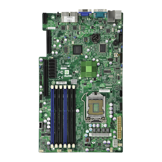
Chapter 1: Introduction Chapter 1 Introduction Overview Checklist Congratulations on purchasing your computer motherboard from an acknowledged leader in the industry. Supermicro boards are designed with the utmost attention to detail to provide you with the highest standards in quality and performance. Please check that the following items have all been included with your motherboard. - Page 10 X8SIU-F User’s Manual Motherboard Image Note: All graphics shown in this manual were based upon the latest PCB Revi- sion available at the time of publishing of the manual. The motherboard you've received may or may not look exactly the same as the graphics shown in this...
- Page 11 Chapter 1: Introduction Motherboard Layout UID-LED COM1 LAN2 LAN1 COM2 JPL1 LAN1 JPL2 LAN2 1-2:ENABLE 1-2:ENABLE 2-3:DISABLE 2-3:DISABLE JPL1 JPL2 SPKR1 JSPK JTPM JWF1:DOM_PWR 12/13 JPG1 I-SATA5 I-SATA4 JPG1 VGA 1-2:ENABLE 2-3:DISABLE I-SATA3 X8SIU REV:1.00 I-SATA2 JPB:BMC 1-2:ENABLE 2-3:DISABLE I-SATA1 I-SATA0 JPT1:TPM 1-2:Enable...
- Page 12 X8SIU-F User’s Manual UID-LED COM1 LAN2 LAN1 COM2 JPL1 LAN1 JPL2 LAN2 1-2:ENABLE 1-2:ENABLE 2-3:DISABLE 2-3:DISABLE JPL1 JPL2 SPKR1 JSPK JTPM JWF1:DOM_PWR 12/13 JPG1 I-SATA5 I-SATA4 JPG1 VGA 1-2:ENABLE 2-3:DISABLE I-SATA3 X8SIU REV:1.00 I-SATA2 JPB:BMC 1-2:ENABLE 2-3:DISABLE I-SATA1 I-SATA0 JPT1:TPM...
- Page 13 Chapter 1: Introduction Switches, Headers & Connectors Number Connector Description UIOP Universal I/O Power Connector SBX2 SBX2 PCIE Slot, x4 in x8 Slot JWF1 Disk-On-Module (DOM) Power Header Chassis Intrusion Header T-SGPIO-1/2 Serial General Purpose I/O Headers (for SATA) SATA 0~5 SATA Ports (0~5) SBX1 SBX1 PCIE 2.0 Slot (x16 or x8 + x8, set by jumper 25)
- Page 14 X8SIU-F User’s Manual Jumpers Jumper Description Default Number Pins 1-2 (Enabled) BMC Jumper Pins 1-2 (PCIE x16) SBX1 Slot Configuration Select Pins 2-3 (PCIE x8 + x8) JSPK External Speaker Select Pins 1-2 (External) Pins 3-4 (Onboard) Pins 1-2 (Enabled)
-
Page 15: Motherboard Features
Chapter 1: Introduction Motherboard Features Single Intel ® Xeon ® 3400 and L3400 Series, Core Dual Core, Core i3, Pentium ® and Celeron ® processors (LGA1156 socket) Memory Six (6) 240-pin, DDR3 ECC SDRAM DIMM sockets with support for up to 16GB of UDIMM or up to 32GB of RDIMM (with Xeon CPU only) 1333/1066/800 MHz memory. - Page 16 Modulation) fan speed control Low noise fan speed control System Management PECI (Platform Environment Configuration Interface) 2.0 support System resource alert via Supero Doctor III SuperoDoctor III, Watch Dog, NMI Chassis Intrusion Header and Detection CD Utilities BIOS flash upgrade utility Drivers and software for Intel®...
-
Page 17: Block Diagram
W83627DHG LPC I/O RoHS 6/6 HEALTH INFO X8SIU-F System Block Diagram Note: This is a general block diagram and may not exactly represent the features on your motherboard. See the Motherboard Features pages for the actual specifications of each motherboard. -
Page 18: Chipset Overview
The Intel 3420 chipset features a high-speed Direct Media Interface (DMI) for chip-to-chip true isochronous communication with the processor. This feature al- lows the X8SIU-F to achieve up to 10 Gb/s of software-transparent data transfer in each direction, achieving better performance than comparable systems. The... -
Page 19: Pc Health Monitoring
Users can adjust the voltage thresholds to define the sensitivity of the voltage monitor by using SD III. Fan Status Monitor with Software PC health monitoring can check the RPM status of the cooling fans via Supero Doctor III. CPU Overheat LED and Control This feature is available when the user enables the CPU overheat warning feature in the BIOS. -
Page 20: Slow Blinking Led For Suspend-State Indicator
X8SIU-F User’s Manual Slow Blinking LED for Suspend-State Indicator When the CPU goes into a suspend state, the chassis power LED will start blink- ing to indicate that the CPU is in the suspend mode. When the user presses any key, the CPU will wake-up and the LED indicator will automatically stop blinking and remain on. -
Page 21: Super I/O
Chapter 1: Introduction Super I/O The X8SIU-F provides two high-speed, 16550-compatible serial communication ports (UARTs). This UART includes a 16-byte send/receive FIFO, a programmable baud rate generator, complete modem control capability and a processor interrupt system. Both UARTs provide legacy speed with baud rate of up to 115.2 Kbps as well as an advanced speed with baud rates of 250 K, 500 K, or 1 Mb/s, which sup- port higher speed modems. -
Page 22: Overview Of The Nuvoton Bmc Controller
M150GA0BX5) and Nuvoton WPCM450 (Manufacturer P/N WPCM450RA0BX). The Nuvoton WPCM450 has all the features described above plus IPMI 2.0 support. This particular chip is installed in the X8SIU-F motherboard model. Note: For more information on IPMI configuration, please refer to the Embed- ded IPMI User's Guide posted on our website @ http://www.supermicro.com/... -
Page 23: Chapter 2 Installation
Chapter 2: Installation Chapter 2 Installation 2-1 Electro-Static Sensitive Devices Electro-Static Discharge (ESD) can damage electronic com ponents. To prevent damage to your system board, it is important to handle it very carefully. The following measures are generally sufficient to protect your equipment from ESD. Precautions •... -
Page 24: Processor And Heatsink Installation
X8SIU-F User's Manual Processor and Heatsink Installation Warning: When handling the processor package, avoid placing direct pressure on the label area of the fan. Notes: Always connect the power cord last and always remove it before add- ing, removing or changing any hardware components. Make sure that you install the processor into the CPU socket before you install the CPU heatsink. - Page 25 Chapter 2: Installation Gently lift the load lever to open the load plate. Remove the plastic cap. Use your thumb and your index finger to hold the CPU at the top center edge and the bottom center edge of the CPU. Align the CPU key that is the semi-circle cutouts against the socket keys.
- Page 26 X8SIU-F User's Manual Do not rub the CPU against the surface or against any pins of the socket to avoid damage to the CPU or the socket.) With the CPU inside the socket, inspect the four corners of the CPU to make sure that the CPU is properly installed.
-
Page 27: Installing A Passive Cpu Heatsink
Chapter 2: Installation Installing a Passive CPU Heatsink Do not apply any thermal grease to the heatsink or the CPU die -- the required amount has already been applied. Place the heatsink on top of the CPU so that the four mounting holes are aligned with those on the Motherboard's and the Heatsink Bracket under- neath. -
Page 28: Removing The Heatsink
X8SIU-F User's Manual Removing the Heatsink Warning: We do not recommend that the CPU or the heatsink be removed. However, if you do need to uninstall the heatsink, please follow the instruc- tions below to uninstall the heatsink to prevent damage done to the CPU or the CPU socket. -
Page 29: System Memory
Repeat step 1 to install DIMM1B if needed. See Page 3-13 for details. Memory Support The X8SIU-F supports up to 16GB of DDR3 ECC UDIMM or up to 32GB of ECC DDR3 RDIMM (1333/1066/800 MHz in 6 DIMM slots.) Populating these DIMM modules with a pair of memory modules of the same type and same size will result in interleaved memory, which will improve memory performance. -
Page 30: Memory Population Guidelines
SBX1: PCI-E 2.0 X16 or X8+X8 JL1:CHASSIS INSTRUSION T-SGPIO1 T-SGPIO2 USB 4 C490 Memory Population Guidelines Please follow the tables below when populating the X8SIU-F. DDR3 ECC UDIMM Memory DIMM Slots DIMMs DIMM Type POR Speeds Ranks per DIMM per Channel... - Page 31 Chapter 2: Installation DDR3 ECC RDIMM Memory DIMM Slots DIMMs DIMM Type POR Speeds Ranks per DIMM per Channel Populated (any combination) per Channel Registered 1066, 1333 Single Rank, Dual DDR3 ECC Rank Registered 1066 Quad Rank DDR3 ECC Registered 1066, 1333 Single Rank, Dual DDR3 ECC...
-
Page 32: Installing And Removing Dimms
X8SIU-F User's Manual Installing and Removing DIMMs Position the DIMM module's bottom key, so it aligns with the receptive point on the slot. Notches Release Push the Lock/Release tabs to their Release po- sitions. Make sure that the DIMM module's side... - Page 33 Chapter 2: Installation Note: Due to memory allocation to system devices, the amount of memory that remains available for operational use will be reduced when 4 GB of RAM is used. The reduction in memory availability is disproportional. For Microsoft Windows users: Microsoft implemented a design change in Win- dows XP with Service Pack 2 (SP2) and Windows Vista.
-
Page 34: Tools Needed
X8SIU-F User's Manual Motherboard Installation All motherboards have standard mounting holes to fit different types of chassis. Make sure that the locations of all the mounting holes for both motherboard and chassis match. Although a chassis may have both plastic and metal mounting fas- teners, metal ones are highly recommended because they ground the motherboard to the chassis. -
Page 35: Installation Instructions
Chapter 2: Installation Installation Instructions Locate the mounting holes on the motherboard. Refer to the layout on the previous page for mounting hole locations. Locate the matching mounting holes on the chassis. Install standoffs in the chassis as needed. Align the mounting holes on the motherboard against the mounting holes on the chassis. -
Page 36: Connectors/Io Ports
X8SIU-F User's Manual Connectors/IO Ports The I/O ports are color coded in conformance with the PC 99 specification. See the figure below for the colors and locations of the various I/O ports. Back Panel Connectors and IO Ports UID-LED COM1... -
Page 37: Universal Serial Bus (Usb)
Chapter 2: Installation Universal Serial Bus (USB) Back Panel USB 0/1 Pin Definitions Two Universal Serial Bus ports (USB Pin# Definition Pin# Definition 0/1) are located on the I/O back panel and an additional six USB ports in USB_PN1 USB_PN0 three headers, USB 2/3, 10/11, 12/13 USB_PP1 USB_PP0 provide front/back chassis access. -
Page 38: Ethernet Ports
An IPMI Dedicated LAN Vcc19-LAN Link 1000 LED port is also located above USB ports TD3+ Link 100 LED 0/1 on the X8SIU-F. This provides a TD3- 3.3V dedicated network connection for IPMI TD2+- Act LED 2.0 support. These ports accept RJ45 TD2- type connectors/cables. -
Page 39: Serial Ports
Chapter 2: Installation Serial Ports Serial Port Pin Definitions (COM1/COM2) The COM1 Port is located on the Pin # Definition Pin # Definition I/O back panel. COM2 is a header located on the the motherboard. See the table on the right for pin defini- tions. -
Page 40: Video Connector
X8SIU-F User's Manual Video Connector A Video (VGA) connector is located next to the COM 1 Port on the I/O back panel. This connector is used to provide video signals to the display. Refer to the board layout below for the location. -
Page 41: Front Control Panel
Chapter 2: Installation Front Control Panel JF1 contains header pins for various buttons and indicators that are normally lo- cated on a control panel at the front of the chassis. These connectors are designed specifically for use with Supermicro server chassis. See the figure below for the descriptions of the various control panel buttons and LED indicators. -
Page 42: Front Control Panel Pin Definitions
X8SIU-F User's Manual Front Control Panel Pin Definitions Power LED Power LED Pin Definitions (JF1) The Power LED connection is located Pin# Definition on pins 15 and 16 of JF1. Refer to the table on the right for pin definitions. Ground HDD LED The HDD LED onnections are located HDD LED on pins 13 and 14 of JF1. -
Page 43: Nic1/Nic2 (Lan1/Lan2)
Chapter 2: Installation NIC1/NIC2 (LAN1/LAN2) LAN1/LAN2 LED Pin Definitions (JF1) The NIC (Network Interface Control- Pin# Definition ler) LED connection for LAN port 1 is 9/11 located on pins 11 and 12 of JF1, and 10/12 LAN Act the LED connection for LAN Port 2 is on Pins 9 and 10. -
Page 44: Reset Button
X8SIU-F User's Manual Reset Button Reset Button The Reset Button connection is located Pin Definitions (JF1) on pins 3 and 4 of JF1. Attach it to a the Pin# Definition hardware Reset Button on the computer Reset case. Refer to the table on the right for Ground pin definitions. -
Page 45: Connecting Cables
Chapter 2: Installation Connecting Cables This section provides brief descriptions and pin-out definitions for onboard headers and connectors. Be sure to use the correct cable for each header or connector. ATX Power 24-pin Connector ATX/Auxiliary Power Connectors Pin Definitions (JPW1) A 24-pin main power connector is locat- Pin# Definition Pin #... -
Page 46: Fan Headers
X8SIU-F User's Manual Fan Headers Fan Header Pin Definitions The X8SIU-F has four fan headers (Fan1 Pin# Definition ~ Fan4). These fans are 4-pin fan headers. Ground (Black) However, Pins 1-3 of the fan headers are +12V (Red) backward compatible with the traditional 3-pin Tachometer fans. -
Page 47: Internal Speaker/Buzzer
Chapter 2: Installation Internal Speaker/Buzzer Internal Buzzer Pin Definition The Internal Speaker/Buzzer (SPKR1) Pin# Definitions can be used to provide audible indica- Pin 1 Pos. (+) Beep In tions for various beep codes. See the Pin 2 Neg. (-) Alarm table on the right for pin definitions. Speaker Refer to the layout below for the loca- tion of the Internal Speaker/Buzzer. -
Page 48: Onboard Power Led
X8SIU-F User's Manual Onboard Power LED Onboard PWR LED Pin Definitions An onboard Power LED header is Pin# Definition located at JLED. This Power LED header is connected to Front Control No Connection Panel located at JF1 to indicate the Connection to PWR status of system power. -
Page 49: T-Sgpio 1/2 Headers
Chapter 2: Installation T-SGPIO 1/2 Headers Serial_Link-SGPIO Pin Definitions Two T-SGPIO (Serial-Link General Pur- Pin# Definition Definition pose Input/Output) headers are located near the SATA connectors on the moth- Data Out Ground erboard. These headers are used to Ground Load communicate with the enclosure manage- Clock ment chip in the system. -
Page 50: Universal I/O Power Connector (Uiop)
X8SIU-F User's Manual Universal I/O Power Connector (UIOP) Universal I/O Power Connector Pin Definitions (UIOP) The Universal I/O Power (UIOP) Con- Pin# Definition Pin # Definition nector is required for riser cards installed P3V3 on the motherboard. Please connect the P3V3 riser card to the UIOP connector to pro-... -
Page 51: Unit Id Switch
Chapter 2: Installation Unit ID Switch UID Switch There are three Unit Identification (UID) Pin# Definition devices on the motherboard. A rear UID Ground switch and a rear UID LED indicator. The Ground Front Panel UID LED is connected to a pin Button In in the Front Control Panel (Pin 7 of JF1). -
Page 52: Jumper Settings
X8SIU-F User's Manual Jumper Settings Explanation of Jumpers To modify the operation of the motherboard, jumpers can be used to choose between optional settings. Jumpers create shorts be- tween two pins to change the function of the connector. Pin 1 is identified with a square solder pad on the printed circuit board. -
Page 53: Cmos Clear
Chapter 2: Installation CMOS Clear JBT1 is used to clear CMOS. Instead of pins, this "jumper" consists of contact pads to prevent accidental clearing of CMOS. To clear CMOS, use a metal object such as a small screwdriver to touch both pads at the same time to short the connection. Always remove the AC power cord from the system before clearing CMOS. -
Page 54: Usb Wake-Up
X8SIU-F User's Manual USB Wake-Up JPUSB1 (USB Wake-up Enable) Use the JPUSB1 jumper to "wake-up" your Pin# Definition system by pressing a key on a USB keyboard Enabled (Default) or clicking the USB mouse. The JPUSB1 Disabled jumper is used together with the USB Wake- Up feature in the BIOS. -
Page 55: Onboard Indicators
In addition to LAN ports, an IPMI Dedicated Link LED Activity LED LAN is also installed on the X8SIU-F. The yellow LED on the right indicates activity, while the green LED on the left indicates the speed of the connection. See the tables at right for more information. -
Page 56: Onboard Standby Power Led
X8SIU-F User's Manual Onboard Standby Power LED Onboard Standby PWR LED LED Settings An Onboard Standby Power LED is located LED Color Definition at LE4 on the motherboard. When LE4 is System Off on, the AC power cable is connected. Make... -
Page 57: Unit Id Led
Chapter 2: Installation Unit ID LED UID LED (LE5) LED Settings The rear UID LED is located at LE5 on the Blue: Steady UID: On backplane. This LED is used in conjunction with the front UID LED and the rear UID switch to provide easy identification of a system that might be in need of service. -
Page 58: Sata Drive Connections
X8SIU-F User's Manual SATA Drive Connections SATA Connectors SATA Connections Pin Definitions Six Serial ATA (SATA) connectors (I-SATA Pin# Signal 0~5) are located on the motherboard. These Ground Serial Link connections provide faster data SATA_TXP transmission than legacy Parallel ATA. See SATA_TXN the table on the right for pin definitions. -
Page 59: Chapter 3 Troubleshooting
Chapter 3: Troubleshooting Chapter 3 Troubleshooting Troubleshooting Procedures Use the following procedures to troubleshoot your system. If you have followed all of the procedures below and still need assistance, refer to the ‘Technical Support Procedures’ and/or ‘Returning Merchandise for Service’ section(s) in this chapter. Always disconnect the AC power cord before adding, changing or installing any hardware components. -
Page 60: Memory Errors
X8SIU-F User's Manual 2. Use the speaker to determine if any beep codes exist. (Refer to Appendix A for details on beep codes.) 3. Remove all memory modules and turn on the system. (If the alarm is on, check the specs of memory modules, reset the memory or try a different one.) Memory Errors 1. -
Page 61: Frequently Asked Questions
Frequently Asked Questions Question: What type of memory does my motherboard support? Answer: The X8SIU-F supports up to 32GB of Registered ECC DDR3 or up to 16GB of unbuffered ECC DDR3 SDRAM (1.5V, 1333/1066/800 MHz). See Section 3-3 for details on installing memory. - Page 62 Windows, security and audio drivers. Question: How do I solve an error message “IASTOR.SYS read error” when installing Windows and "press F6 to install Intel RAID driver" on my X8SIU-F motherboard? Answer: To solve this issue, disable the IPMI jumper. Another solution is to use a USB floppy drive instead of the onboard floppy drive.
- Page 63 Chapter 3: Troubleshooting Question: What is the heat sink part number for my X8SIU-F mother- board? Answer: For the 1U passive heat sink, ask for SNK-P0046P (back plate is included). Question: Why can't I recover the BIOS even when I’ve followed the instruc- tions in the user’s manual for X8SIU-F?
-
Page 64: Battery Removal And Installation
X8SIU-F User's Manual Battery Removal and Installation Battery Removal To remove the onboard battery, follow the steps below: Battery Lock Power off your system and unplug Battery your power cable. Locate the onboard battery as shown Battery Holder on the right. -
Page 65: Returning Merchandise For Service
Chapter 3: Troubleshooting Returning Merchandise for Service A receipt or copy of your invoice marked with the date of purchase is required before any warranty service will be rendered. You can obtain service by calling your vendor for a Returned Merchandise Authorization (RMA) number. (For faster service, you may also obtain RMA authorizations online (http://www.supermicro. - Page 66 X8SIU-F User's Manual Notes...
-
Page 67: Chapter 4 Bios
BIOS Introduction This chapter describes the AMI BIOS Setup Utility for the X8SIU-F. The AMI ROM BIOS is stored in a Flash EEPROM and can be easily updated. This chapter de- scribes the basic navigation of the AMI BIOS Setup Utility setup screens. -
Page 68: How To Start The Setup Utility
X8SIU-F How to Start the Setup Utility Normally, the only visible Power-On Self-Test (POST) routine is the memory test. As the memory is being tested, press the <Delete> key to enter the main menu of the AMI BIOS Setup Utility. From the main menu, you can access the other setup screens. - Page 69 <Tab> key or the arrow keys to move between fields. The date must be entered in Day MM/DD/YY format. The time is entered in HH:MM:SS format. (Note: The time is in the 24-hour format. For example, 5:30 P.M. appears as 17:30:00.) Supermicro X8SIU-F Version Build Date...
-
Page 70: 4-3 Advanced Setup Configurations
X8SIU-F 4-3 Advanced Setup Configurations Use the arrow keys to select Boot Setup and hit <Enter> to access the submenu items: BOOT Feature Quick Boot If Enabled, this option will skip certain tests during POST to reduce the time needed for system boot. The options are Enabled and Disabled. - Page 71 Chapter 4: AMI BIOS Wait For 'F1' If Error This forces the system to wait until the 'F1' key is pressed if an error occurs. The options are Disabled and Enabled. Hit 'Del' Message Display This feature displays "Press DEL to run Setup" during POST. The options are Enabled and Disabled.
- Page 72 X8SIU-F Processor & Clock Options Warning : Take Caution when changing the Advanced settings. An incorrect value, a very high DRAM frequency or incorrect DRAM timing may cause system to become unstable. When this occurs, revert to the default setting.
- Page 73 Chapter 4: AMI BIOS Execute-Disable Bit Capability (Available when supported by the OS and the CPU) Set to Enabled to enable the Execute Disable Bit which will allow the processor to designate areas in the system memory where an application code can execute and where it cannot, thus preventing a worm or a virus from flooding illegal codes to overwhelm the processor or damage the system during an attack.
-
Page 74: Advanced Chipset Control
X8SIU-F C3 Auto Demotion When enabled, the CPU will conditionally demote C6 or C7 requests to C3 based on un-core auto-demote information. The options are Disabled and Enabled. Advanced Chipset Control The items included in the Advanced Settings submenu are listed below. - Page 75 Chapter 4: AMI BIOS Configure SATA as This feature allows the user to select the drive type for SATA#1. The options are IDE, RAID and AHCI. PCH RAID CodeBase (Available if RAID is selected above) Select Intel to enable the Intel SATA Host RAID Utility. Select Adaptec to use the Adaptec Host RAID Utility.
- Page 76 X8SIU-F PIO Mode The IDE PIO (Programmable I/O) Mode programs timing cycles between the IDE drive and the programmable IDE controller. As the PIO mode increases, the cycle time decreases. The options are Auto, 0, 1, 2, 3, and 4.
- Page 77 Chapter 4: AMI BIOS Select UDMA2 to allow the BIOS to use Ultra DMA mode 2. It has a data transfer rate of 33.3 MB/s. Select UDMA3 to allow the BIOS to use Ultra DMA mode 3. It has a data transfer rate of 44.4 MB/s.
- Page 78 X8SIU-F ROM Scan Ordering This item determines what kind of option ROM activates over another. The options are Onboard First and Add-on First. SBX2 PCIe x4 OPROM Use this feature to enable or disable PCI slot Option ROMs. The options are Dis- abled and Enabled.
-
Page 79: Hardware Health Configuration
Chapter 4: AMI BIOS Serial Port Number This feature allows the user to decide which serial port to be used for Console Redirection. The options are COM 1 and COM 3. Note: Serial Over LAN (SOL) will be enabled when COM 3 is selected. Serial Port Mode This feature allows the user to set the serial port mode for Console Redirection. - Page 80 X8SIU-F Warning: Any temperature that exceeds the CPU threshold temperature predefined by the CPU manufacturer may result in CPU overheat or system instability. When the CPU temperature reaches this predefined threshold, the CPU and system cooling fans will run at full speed.
- Page 81 Chapter 4: AMI BIOS even with the CPU fan running at full speed, the system buzzer will activate and the Overheat LED will turn on. The Early Alarm – the Overheat LED and system buzzer will be activated exactly when the High level is reached. The CPU fan will run at full speed to bring the CPU temperature down.
- Page 82 X8SIU-F system cooling. The Performance setting is recommended for high-power-consum- ing and high-density systems. Select Balanced for the onboard fans to run at 50% of the Initial PWM Cycle in order to balance the needs between system cooling and power saving. The Balanced setting is recommended for regular systems with normal hardware configurations.
- Page 83 Chapter 4: AMI BIOS ACPI APIC Support Select Enabled to include the ACPI APIC Table Pointer in the RSDT (Root System Description Table) pointer list. The options are Enabled and Disabled. APIC ACPI SCI IRQ When this item is set to Enabled, APIC ACPI SCI IRQ is supported by the system. The options are Enabled and Disabled.
- Page 84 X8SIU-F Set this feature to configure the IPMI LAN adapter with a network address. Channel Number - Enter the channel number for the SET LAN Config com- mand. This is initially set to [1]. Press <+> or < - > on your keyboard to change the Channel Number.
- Page 85 Chapter 4: AMI BIOS Event Log Configuration View Event Log Use this option to view the System Event Log. Mark all events as read This option marks all events as read. The options are OK and Cancel. Clear event log This option clears the Event Log memory of all messages. The options are OK and Cancel.
-
Page 86: Security Settings
X8SIU-F Security Settings The AMI BIOS provides a Supervisor and a User password. If you use both pass- words, the Supervisor password must be set first. Supervisor Password This item indicates if a supervisor password has been entered for the system. Clear means such a password has not been used and Set means a supervisor password has been entered for the system. -
Page 87: Boot Settings
Chapter 4: AMI BIOS Clear User Password (Available only if User Password has been set) Password Check Available options are Setup and Always. Boot Sector Virus Protection When Enabled, the AMI BOIS displays a warning when any program (or virus) is- sues a Disk Format command or attempts to write to the boot sector of the hard disk drive. -
Page 88: Exit Options
X8SIU-F Hard Disk Drives This feature allows the user to specify the sequence of priority from the available Hard Drives. • 1st Drive [SATA: XXXXXXXXXX] • 2nd Drive [SATA: XXXXXXXXXX] Removable Drives This feature allows the user to specify the boot sequence from available Removable Drives. - Page 89 Chapter 4: AMI BIOS Save Changes and Exit When you have completed the system configuration changes, select this option to leave the BIOS Setup Utility and reboot the computer, so the new system con- figuration parameters can take effect. Select Save Changes and Exit from the Exit menu and press <Enter>.
- Page 90 X8SIU-F Notes 4-24...
-
Page 91: Appendix A Post Error Beep Codes
Appendix A: POST Error Beep Codes Appendix A POST Error Beep Codes This section lists POST (Power On Self Test) error beep codes for the AMI BIOS. POST error beep codes are divided into two categories: recoverable and terminal. This section lists Beep Codes for recoverable POST errors. Recoverable POST Error Beep Codes When a recoverable type of error occurs during POST, BIOS will display a POST code that describes the problem. - Page 92 X8SIU-F User's Manual Notes...
-
Page 93: Appendix B Software Installation Instructions
Appendix B: Software Installation Instructions Appendix B Software Installation Instructions B-1 Installing Drivers After you've installed the Windows Operating System, a screen as shown below will appear. You are ready to install software programs and drivers that have not yet been installed. To install these software programs and drivers, click the icons to the right of these items. -
Page 94: Configuring Supero Doctor Iii
The Supero Doctor III program is a Web-based management tool that supports remote management capability. It includes Remote and Local Management tools. The local management is called the SD III Client. The Supero Doctor III program included on the CDROM that came with your motherboard allows you to monitor the environment and operations of your system. - Page 95 Appendix B: Software Installation Instructions Supero Doctor III Interface Display Screen-II (Remote Control) Note: SD III Software Revision 1.0 can be downloaded from our Web site at: ftp://ftp.supermicro.com/utility/Supero_Doctor_III/. You can also download SDIII User's Guide at: http://www.supermicro.com/PRODUCT/ Manuals/SDIII/UserGuide.pdf. For Linux, we will still recommend that you...
- Page 96 X8SIU-F User's Manual Notes...
-
Page 97: Appendix C - Bios Recovery
Appendix C: BIOS Recovery Appendix C - BIOS Recovery The recovery procedure described in this section is to be used only when you are advised by your Supermicro Technical Support representative, or in cases of emer- gencies where the system can no longer boot due to a corrupted BIOS. DO NOT re-program (re-flash) the BIOS if your system is running properly. -
Page 98: Recovery Process From An Ide/Sata Atapi Disc Drive
X8SIU-F User’s Manual When the Boot Sector Recovery Process is complete, the system will reboot automatically and you will see a checksum error on your screen. Part 2: BIOS Reprogramming (Re-Flashing) After completing the Boot Sector Recovery Process, you will need to reprogram (“re-flash”) the proper BIOS binary file again into the BIOS ROM in order to have... - Page 99 (Disclaimer Continued) The products sold by Supermicro are not intended for and will not be used in life support systems, medical equipment, nuclear facilities or systems, aircraft, aircraft devices, aircraft/emergency communication devices or other critical systems whose failure to perform be reasonably expected to result in significant injury or loss of life or catastrophic property damage.
Need help?
Do you have a question about the X8SIU-F and is the answer not in the manual?
Questions and answers