Supero Super X8DT3 User Manual
Hide thumbs
Also See for Super X8DT3:
- User manual (95 pages) ,
- User manual (97 pages) ,
- User manual (99 pages)
Table of Contents
Advertisement
Advertisement
Table of Contents

Related Manuals for Supero Super X8DT3


Summary of Contents for Supero Super X8DT3
- Page 1 Инструкция SuperMicro X8DTi-F Перейти в карточку товара 8 800 775 98 98...
- Page 2 X8DT3 X8DTi X8DT3-F X8DTi-F X8DT3-LN4F X8DTi-LN4F USER’S MANUAL Revision 1.2c...
- Page 3 This product, including software and docu- mentation, is the property of Supermicro and/or its licensors, and is supplied only under a license. Any use or reproduction of this product is not allowed, except as expressly permitted by the terms of said license.
-
Page 4: About This Manual
High Performance Computing (HPC) systems and intensive applications. Please refer to our web site (http://www.supermicro.com/products/) for updates on supported processors. This product is intended to be installed and serviced by professional technicians. (*The 5600 Series processors are supported by a Rev. -
Page 5: Conventions Used In The Manual
X8DT3/X8DTi/X8DT3-F/X8DTi-F/X8DT3-LN4F/X8DTi-LN4F User's Manual Conventions Used in the Manual Special attention should be given to the following symbols for proper installation and to prevent damage done to the components or injury to yourself: Danger/Caution: Instructions to be strictly followed to prevent catastrophic system failure or to avoid bodily injury. -
Page 6: Contacting Supermicro
Super Micro Computer, Inc. 980 Rock Ave. San Jose, CA 95131 U.S.A. Tel: +1 (408) 503-8000 Fax: +1 (408) 503-8008 Email: marketing@supermicro.com (General Information) support@supermicro.com (Technical Support) Web Site: www.supermicro.com Europe Address: Super Micro Computer B.V. Het Sterrenbeeld 28, 5215 ML... -
Page 7: Table Of Contents
X8DT3/X8DTi/X8DT3-F/X8DTi-F/X8DT3-LN4F/X8DTi-LN4F User's Manual Table of Contents Preface Chapter 1 Introduction Overview ......................1-1 Chipset Overview .................... 1-9 Special Features ................... 1-10 PC Health Monitoring ..................1-10 ACPI Features ....................1-11 Power Supply ....................1-12 Super I/O ....................... 1-12 Overview of the Winbond WPCM450 Controller (For X8DT3/i-F/X8DT3/i-LN4F Only) ........................ - Page 8 Table of Contents Chassis Intrusion ..................2-23 Internal Speaker ..................2-24 Power LED/Speaker ................. 2-24 Wake-On-LAN ..................2-25 Overheat LED/Fan Fail (JOH1) ..............2-25 T-SGPIO Headers ..................2-26 I-Button (Optional for X8DT3/-F/LN4F only) ..........2-26 Power SMB (I C) Connector ..............2-27 IPMB I C SMB ..................
- Page 9 X8DT3/X8DTi/X8DT3-F/X8DTi-F/X8DT3-LN4F/X8DTi-LN4F User's Manual Frequently Asked Questions ................3-3 Returning Merchandise for Service..............3-4 Chapter 4 BIOS Introduction ...................... 4-1 Starting BIOS Setup Utility ................4-1 ............4-2 Starting the Setup Utility ................. 4-2 Main Setup ...................... 4-2 ..............4-4 Security Settings ................... 4-24 ..................
-
Page 10: Chapter 1 Introduction
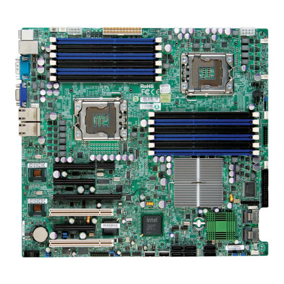
Checklist Congratulations on purchasing your computer motherboard from an acknowledged leader in the industry. Supermicro boards are designed with the utmost attention to detail to provide the highest standards in quality and performance. Check that the following items have all been included with your motherboard. If anything listed here is damaged or missing, contact your retailer. - Page 11 X8DT3/X8DTi/X8DT3-F/X8DTi-F/X8DT3-LN4F/X8DTi-LN4F User's Manual X8DT3/X8DTi/X8DT3-F/X8DTi-F/X8DT3-LN4F/X8DTi-LN4F Image Note: The drawings and pictures shown in this manual were based on the latest PCB Revision available at the time of publishing of the manual. The motherboard you’ve received may or may not look exactly the same as the graphics shown in the manual.
- Page 12 IPMI Dedicated LAN is for X8DT3/i-F, X8DT3/i-LN4F only. 2. SAS connectors, jumpers, and the LSI 1068E chip are available on the Guide posted on our website @ http://www.supermicro.com/support/manuals/ 3. IPMI 2.0 and the Dedicated LAN (w/KVM support) are available on the X8DT3/i-F/-LN4F only.
-
Page 13: Motherboard Layout
1. Jumpers not indicated are for test purposes only. please refer to the Winbond BMC User's Guide posted on our website @ http://www.supermicro.com/support/manuals/. 3. " " indicates the location of Pin 1. Also, refer to Chapter 2 for detailed infor- mation on the onboard components. - Page 14 Chapter 1: Introduction Quick Reference Jumper Description Default Setting JBT1 CMOS Clear (See Section 5-10) C1/JI SMB to PCI Slots 2-3 (Disabled) BMC Enable (for F models) Pins 1-2 (Enabled) (for R. 2.00 & later board) JPG1 VGA Enable Pins 1-2 (Enabled) JPL1/JPL2 LAN1/2 &...
-
Page 15: Motherboard Features
X8DT3/X8DTi/X8DT3-F/X8DTi-F/X8DT3-LN4F/X8DTi-LN4F User's Manual Motherboard Features ® Two Intel 5500/5600* Series (LGA 1366) processors, each processor support- ing two full-width Intel QuickPath Interconnect links with a total of up to 51.2 GB/s Data Transfer Rate (6.4 GB/s per direction) Memory DIMM sockets support up to 192 GB of DDR3 Reg. ECC or up to 48 GB of DDR3 Unbuffered ECC/Non-ECC 1333 MHz/1066 MHz/800 MHz memory in 12 slots Chipset Intel 5520 chipset, including: the 5520 (North Bridge) and the ICH10R (South... - Page 16 Dimensions Ext. ATX 12.00" (L) x 13.00" (W) (304.80 mm x 330.20 mm) Note 1: please refer to the Intel SATA HostRAID User's Guide posted at http://www.supermicro.com/ support/manuals/. Note 2: please refer to the LSI MegaRAID User's Guide posted at http://www.supermicro.com/sup- port/manuals/.
- Page 17 X8DT3/X8DTi/X8DT3-F/X8DTi-F/X8DT3-LN4F/X8DTi-LN4F User's Manual #1-6 #0-6 #1-5 #0-5 #1-4 #0-4 #1-3 #0-3 6 PHASE 6 PHASE #1-2 #0-2 #1-1 #0-1 PROCESSOR#2 PROCESSOR#1 (Optional) PCI-E X16 Ports #7-10 Port PHY#1 LAN#2 Ports 82576EB Intel 5520 PHY#2 Option #1-2 Port Ports#0~3 LSI 1068 Ports#4~7 Option Ports...
-
Page 18: Chipset Overview
Chapter 1: Introduction Chipset Overview Built upon the capability of the Intel 5520 platform, the X8DT3/X8DTi/X8DT3-F/ X8DTi-F/X8DT3-LN4F/X8DTi-LN4F motherboard provides the performance and tion optimized for workstations, High Performance Computing (HPC) systems, and intensive applications. The 5520 platform consists of the 5500/5600 Series (LGA 1366) processor, the 5520 (North Bridge), and the ICH10R (South Bridge). -
Page 19: Special Features
X8DT3/X8DTi/X8DT3-F/X8DTi-F/X8DT3-LN4F/X8DTi-LN4F User's Manual Special Features Recovery from AC Power Loss BIOS provides a setting for you to determine how the system will respond when AC power is lost and then restored to the system. You can choose for the system to remain powered off (in which case you must press the power switch to turn it back on) or for it to automatically return to a power- on state. -
Page 20: Acpi Features
Chapter 1: Introduction environment or used with Supero Doctor II in Linux. Supero Doctor is used to Supero Doctor to provide you with warnings when the system temperature, CPU ACPI Features way to integrate power management features throughout a PC system, including its hardware, operating system and application software. -
Page 21: Power Supply
X8DT3/X8DTi/X8DT3-F/X8DTi-F/X8DT3-LN4F/X8DTi-LN4F User's Manual (WOL) to connect to the 3-pin header on a Network Interface Card (NIC) that has WOL capability. In addition, an onboard LAN controller can also support WOL without any connection to the WOL header. The 3-pin WOL header is to be used with a LAN add-on card only. -
Page 22: Overview Of The Winbond Wpcm450 Controller (For X8Dt3/I-F/X8Dt3/I-Ln4F Only)
Chapter 1: Introduction ports (UARTs). Each UART includes a 16-byte send/receive FIFO, a programmable baud rate generator, complete modem control capability and a processor interrupt system. Both UARTs provide legacy speed with baud rate of up to 115.2 Kbps as well as an advanced speed with baud rates of 250 K, 500 K, or 1 Mb/s, which support higher speed modems. - Page 23 X8DT3/X8DTi/X8DT3-F/X8DTi-F/X8DT3-LN4F/X8DTi-LN4F User's Manual Notes 1-14...
-
Page 24: Chapter 2 Installation
Chapter 2: Installation Chapter 2 Installation Static-Sensitive Devices Electrostatic Discharge (ESD) can damage electronic com ponents. To prevent dam- age to your system board, it is important to handle it very carefully. The following Precautions Use a grounded wrist strap designed to prevent static discharge. Touch a grounded metal object before removing the board from the antistatic bag. -
Page 25: Motherboard Installation
X8DT3/X8DTi/X8DT3-F/X8DTi-F/X8DT3-LN4F/X8DTi-LN4F User's Manual Motherboard Installation Make sure that the locations of all the mounting holes for both motherboard and chassis match. Although a chassis may have both plastic and metal mounting fasteners, metal ones are highly recommended because they ground the mother- board to the chassis. -
Page 26: Processor And Heatsink Installation
Chapter 2: Installation Processor and Heatsink Installation Warning: When handling the processor package, avoid placing direct pressure on the label area of the fan. Notes: 1. Always connect the power cord last and always remove it before adding, re- moving or changing any hardware components. Make sure that you install the processor into the CPU socket before you install the CPU heatsink. - Page 27 X8DT3/X8DTi/X8DT3-F/X8DTi-F/X8DT3-LN4F/X8DTi-LN4F User's Manual 1. After removing the plastic cap, using your thumb and the index north and south center edges. 2. Align the CPU key, the semi- circle cutout, against the socket key, the notch below the gold color dot on the side of the socket.
-
Page 28: Installing A Cpu Heatsink
Chapter 2: Installation Installing a CPU Heatsink 1. Do not apply any thermal grease to the heatsink or the CPU die because the required amount has already been ap- plied. Screw#1 Screw#2 2. Place the heatsink on top of the CPU so that the four mounting holes are aligned with those on the retention mechanism. - Page 29 X8DT3/X8DTi/X8DT3-F/X8DTi-F/X8DT3-LN4F/X8DTi-LN4F User's Manual Removing the Heatsink Warning: We do not recommend that the CPU or the heatsink be re- moved. However, if you do need to remove the heatsink, please follow the instructions below to uninstall the heatsink and prevent damage to the CPU or other components.
-
Page 30: Memory Installation
Chapter 2: Installation Memory Installation Note: Check the Supermicro web site for recommended memory modules. CAUTION Exercise extreme care when installing or removing DIMM modules to prevent any possible damage. Also note that the memory is interleaved to improve performance (See step 1). -
Page 31: Memory Support
X8DT3/X8DTi/X8DT3-F/X8DTi-F/X8DT3-LN4F/X8DTi-LN4F User's Manual Memory Population for Optimal Performance -For a motherboard with One CPU (CPU1) installed Branch 0 Branch 1 Branch 2 3 DIMMs P1 DIMM1A P1 DIMM2A P1 DIMM3A 6 DIMMs P1 DIMM1A P1 DIMM1B P1 DIMM2A P1 DIMM2B P1 DIMM3A P1 DIMM3B Memory Population for Optimal Performance... - Page 32 Chapter 2: Installation UDIMM Population for the Motherboard w/5500 Processors Installed DIMM DIMMs DIMM Type Speeds (in Ranks per DIMM Slots Populated (Unb.= Unbuffered) MHz) (Mixing: any per Channel combination; Channel SR=Single Rank, DR=Dual Rank) Unb. ECC/NON-ECC DDR3 800,1066,1333 SR or DR Unb.
- Page 33 X8DT3/X8DTi/X8DT3-F/X8DTi-F/X8DT3-LN4F/X8DTi-LN4F User's Manual 1.35V DIMMs 1.35V RDIMM Population for the Motherboard w/5600 Processors Installed DIMM DIMMs DIMM Type Speeds (in MHz) Ranks per DIMM Slots per Populated (Reg.=Registered) (any combination; Channel per Channel SR=Single Rank, DR=Dual Rank, QR=Quad Rank) Reg. DDR3 ECC 800,1066,1333 SR or DR Reg.
- Page 34 Chapter 2: Installation Possible System Memory Allocation & Availability System Device Size Physical Memory Remaining (-Available) (4 GB Total System Memory) 1 MB 3.99 GB BIOS) Local APIC 4 KB 3.99 GB Area Reserved for the chipset 2 MB 3.99 GB I/O APIC (4 Kbytes) 4 KB 3.99 GB...
-
Page 35: Control Panel Connectors/Io Ports
X8DT3/X8DTi/X8DT3-F/X8DTi-F/X8DT3-LN4F/X8DTi-LN4F User's Manual Control Panel Connectors/IO Ports the picture below for the colors and locations of the various I/O ports. 1. Back Panel Connectors/IO Ports Back Panel Connectors 1. Keyboard (Purple) 2. PS/2 Mouse (Green) 3. Back Panel USB Port 0 4. -
Page 36: Atx Ps/2 Keyboard And Ps/2 Mouse Ports
Chapter 2: Installation ATX PS/2 Keyboard and PS/2 PS/2 Keyboard/Mouse Pin Mouse Ports PS2 Keyboard PS2 Mouse The ATX PS/2 keyboard and PS/2 mouse are located next to the Back KB Data Mouse Data Panel USB Ports 0~1 on the moth- No Connection No Connection erboard. -
Page 37: Universal Serial Bus (Usb)
X8DT3/X8DTi/X8DT3-F/X8DTi-F/X8DT3-LN4F/X8DTi-LN4F User's Manual Universal Serial Bus (USB) Back Panel USB Front Panel USB (USB 0/1) (USB 2/3) Two Universal Serial Bus ports (USB 0 and USB 1) are located on the I/O back panel. Additionally, six USB con- Data- nections (USB 2, 3, 4/5, 6/7) on the Data+ motherboard to provide front chassis Ground... -
Page 38: Serial Ports
Chapter 2: Installation Serial Ports Serial Ports-COM1/COM2 Two COM connections (COM1 & COM2) are located on the motherboard. COM1 is located on the Backplane IO panel. COM2 is located next to the onboard battery to provide additional onboard serial connection support. See the table Ground Video Connector A Video (VGA) connector is located... -
Page 39: Ethernet Ports
X8DT3/X8DTi/X8DT3-F/X8DTi-F/X8DT3-LN4F/X8DTi-LN4F User's Manual Ethernet Ports LAN Ports Two Ethernet ports (LAN 1/LAN2) are located at on the IO backplane. In P2V5SB SGND addition, LAN 3/LAN4 are supported TD0+ Act LED on the X8DT3/i-LN4F. A dedicated TD0- P3V3SB LAN is also located on the X8DT3/i-F/ TD1+ Link 100 LED X8DT3/i-LN4F to provide KVM sup-... -
Page 40: Front Control Panel
Chapter 2: Installation 2. Front Control Panel JF1 contains header pins for various buttons and indicators that are normally lo- cated on a control panel at the front of the chassis. These connectors are designed descriptions of the various control panel buttons and LED indicators. Refer to the JF1 Header Pins Ground Power LED... -
Page 41: Nmi Button
X8DT3/X8DTi/X8DT3-F/X8DTi-F/X8DT3-LN4F/X8DTi-LN4F User's Manual NMI Button NMI Button The non-maskable interrupt button header is located on pins 19 and 20 of JF1. Refer to the table on the right Control Ground Power LED Power LED The Power LED connection is located on pins 15 and 16 of JF1. -
Page 42: Hdd Led
Chapter 2: Installation HDD LED The HDD LED connection is located HDD LED on pins 13 and 14 of JF1. Attach a hard drive LED cable here to display disk activity (for any hard drive ac- tivities on the system, including SAS, HD Active Serial ATA and IDE). -
Page 43: Overheat (Oh)/Fan Fail Led
X8DT3/X8DTi/X8DT3-F/X8DTi-F/X8DT3-LN4F/X8DTi-LN4F User's Manual Overheat (OH)/Fan Fail LED OH/Fan Fail LED Connect an LED Cable to the OH/ Fan Fail connection on pins 7 and 8 of JF1 to provide advanced warnings Ground of chassis overheating or fan failure. OH/Fan Fail Indicator Refer to the table on the right for pin Status Normal... -
Page 44: Reset Button
Chapter 2: Installation Reset Button Reset Button The Reset Button connection is located on pins 3 and 4 of JF1. Attach it to a hardware reset switch on the computer Reset case. Refer to the table on the right for Ground Power Button The Power Button connection is located... -
Page 45: Connecting Cables
X8DT3/X8DTi/X8DT3-F/X8DTi-F/X8DT3-LN4F/X8DTi-LN4F User's Manual Connecting Cables ATX Power 24-pin Connector Power Connectors +3.3V +3.3V -12V +3.3V A 24-pin main power supply connector(JPW3) and two 8-pin CPU PWR connectors (JPW1/ PS_ON JPW2) on the motherboard. These power cation. In addition to the 24-pin ATX power connector, the 12V 8-pin CPU PWR connec- tors at JPW1/JPW2 must also be connected Res (NC) -
Page 46: Fan Headers
Chapter 2: Installation Fan Headers Fan Header This motherboard has six chassis/system fan headers (Fan1 to Fan6) and two CPU fans (Fan7/Fan8) on the motherboard. All Ground these 4-pin fans headers are backward +12V compatible with the traditional 3-pin fans. Tachometer However, fan speed control is available PWR Modulation... -
Page 47: Internal Speaker
X8DT3/X8DTi/X8DT3-F/X8DTi-F/X8DT3-LN4F/X8DTi-LN4F User's Manual Internal Speaker Internal Buzzer (SP1) The Internal Speaker, located at SP1, can be used to provide audible indica- Pin 1 Pos. (+) Beep In tions for various beep codes. See the Pin 2 Neg. (-) Alarm Speaker Refer to the layout below for the loca- tions of the Internal Buzzer (SP1). -
Page 48: Wake-On-Lan
Chapter 2: Installation Wake-On-LAN Wake-On-LAN The Wake-On-LAN header is located at JWOL on the motherboard. You +5V Standby must also have a LAN card with a Ground Wake-On-LAN connector and a cable Wake-up to use this feature. See the table on Overheat LED Overheat LED/Fan Fail (JOH1) The JOH1 header is used to connect... -
Page 49: T-Sgpio Headers
X8DT3/X8DTi/X8DT3-F/X8DTi-F/X8DT3-LN4F/X8DTi-LN4F User's Manual T-SGPIO Headers T-SGPIO Two SGPIO (Serial-Link General Purpose Input/Output) headers (T-SGPIO-1/T-SGPIO-2) are located the motherboard. These headers Ground Data support serial link interfaces for the Load Ground onboard SATA and SAS connectors. Note: NC= No Connections tions. Refer to the board layout below for the location. -
Page 50: Power Smb (I 2 C) Connector
Chapter 2: Installation Power SMB (I C) Connector PWR SMB Power System Management Bus C) Connector (J6) monitors power Clock supply, fan and system temperatures. Data See the table on the right for pin PWR Fail Ground +3.3V SMB Header IPMB I C SMB A System Management Bus header... -
Page 51: Tpm Header
X8DT3/X8DTi/X8DT3-F/X8DTi-F/X8DT3-LN4F/X8DTi-LN4F User's Manual TPM Header TPM Header A Trusted Platform Module header (JTPM1) is located next to COM2 port LCLK to provide TPM support for system LFRAME# <(KEY)> data security. See the table on the LRESET# +5V (X) LAD 3 LAD 2 Note: This header is avail- +3.3V... -
Page 52: Jumper Settings
Chapter 2: Installation Jumper Settings Explanation of Jumpers Connector Pins To modify the operation of the mother- board, jumpers can be used to choose between optional settings. Jumpers create Jumper shorts between two pins to change the with a square solder pad on the printed Setting circuit board. -
Page 53: Cmos Clear
X8DT3/X8DTi/X8DT3-F/X8DTi-F/X8DT3-LN4F/X8DTi-LN4F User's Manual CMOS Clear JBT1 is used to clear CMOS. Instead of pins, this "jumper" consists of contact pads to prevent the accidental clearing of CMOS. To clear CMOS, use a metal object such as a small screwdriver to touch both pads at the same time to short the connection. -
Page 54: I 2 C Bus To Pci-Exp. Slots
Chapter 2: Installation C Bus to PCI-Exp. Slots C to PCI-Exp Jumpers JI C1 and JI C2 allow you to Jumper Settings connect the System Management Bus C) to PCI-Express slots. The default Enabled setting is Open to disable the connec- Disabled (Default) tion. -
Page 55: Sas Enable/Disable (X8Dt3/X8Dt3-F/X8Dt3-Ln4F Only)
SAS connections. See the table on the Closed Software RAID (SR) (Default) right for jumper settings. Note: please refer to the LSI MegaRAID User's Guide posted on our website @ http://www. supermicro.com/support/manuals/. SAS Enable KB/MOUSE Fan5 Fan6 JPW3 JPW2 JPW1... -
Page 56: Bmc Enable
Chapter 2: Installation BMC Enable BMC Enable Jumper JPB allows you to enable or Jumper Settings disable embedded the WPCM 450 BMC Controller (Baseboard Manage- Pins 1-2 BMC Enabled (Default) ment Controller) to support IPMI 2.O Pins 2-3 BMC Disabled on theX8DT3/i-F/LN4F. -
Page 57: Onboard Led Indicators
X8DT3/X8DTi/X8DT3-F/X8DTi-F/X8DT3-LN4F/X8DTi-LN4F User's Manual Onboard LED Indicators GLAN LEDs Activity LED Link LED Rear View (when facing the Two LAN ports (LAN 1/LAN 2) are located rear side of the chassis) on the IO Backplane of the motherboard. LAN 1/LAN 2 Activity LED (Left) LED State In addition, LAN3/LAN4 are located on the X8DT3/i-LN4F. -
Page 58: Sas Heartbeat/Activity Led Indicators
Chapter 2: Installation SAS Heartbeat/Activity LED Indicators Two Onboard SAS LED are located on Onboard SAS LED Indicators (LES1/LES2) Settings the motherboard. LES1 is SAS Heart- beat LED, and LES2 is SAS Activity LES1 Blinking: SAS: Normal LED. When LES1 is blinking, SAS con- LES2 Blinking: SAS: Active nections function normally. -
Page 59: Onboard Power Led
X8DT3/X8DTi/X8DT3-F/X8DTi-F/X8DT3-LN4F/X8DTi-LN4F User's Manual Onboard Power LED Onboard PWR LED (LE1) Settings An Onboard Power LED is located at LE1 on the motherboard. When this LED is lit, System Off (PWR cable not the system is on. Be sure to turn off the connected) system and unplug the power cord before Green... -
Page 60: Floppy Drive, Serial Ata And Sas Connections
Chapter 2: Installation Floppy Drive, Serial ATA and SAS Connections A red mark on a wire typically designates the location of pin 1. connects to drive A, and the connector that does not have twisted wires always connects to drive B. Floppy Drive Connector Ground FDHDIN... -
Page 61: Serial Ata Ports
X8DT3-LN4F. See the layout below for SAS port locations. Note 1: please refer to the Intel SATA HostRAID User's Guide posted on our website @ http://www.supermicro.com/support/manuals/. Note 2: please refer to the LSI MegaRAID User's Guide posted on our website @ http:// www.supermicro.com/support/manuals/. -
Page 62: Chapter 3 Troubleshooting
Chapter 3: Troubleshooting Chapter 3 Troubleshooting Troubleshooting Procedures Use the following procedures to troubleshoot your system. If you have followed all of the procedures below and still need assistance, refer to the ‘Technical Support Procedures’ and/or ‘Returning Merchandise for Service’ section(s) in this chapter. Note: Always disconnect the power cord before adding, changing or installing any hardware components. -
Page 63: Memory Errors
7. Please follow the instructions given in the DIMM Population Tables listed on Section 2-4 (Chapter 2) to install your memory modules. Technical Support Procedures Before contacting Technical Support, please take the following steps. Also, please note that as a motherboard manufacturer, Supermicro does not sell directly to end-... -
Page 64: Frequently Asked Questions
Distributors: For immediate assistance, please have your account number ready when placing a call to our technical support department. We can be reached by e-mail at support@supermicro.com or by fax at: (408) 503-8000, option 2. Frequently Asked Questions Question: What are the types of memory can be supported by my board? -
Page 65: Returning Merchandise For Service
Notes: 1. The SPI BIOS chip used on this motherboard cannot be removed. Send your motherboard back to our RMA Department at Supermicro for repair. 2. For AMI BIOS Recovery, please refer to the AMI BIOS Recovery Instructions posted on our website at http://www.supermicro.com/support/... -
Page 66: Chapter 4 Bios
When an option is selected in the left frame, it is highlighted in white. Often a text message will accompany it. (Note: the AMI BIOS has default text messages built in. Supermicro retains the option to include, omit, or change any of these text messages.) The AMI BIOS Setup Utility uses a key-based navigation system called "hot keys". -
Page 67: Starting The Setup Utility
Warning! Do not upgrade the BIOS unless your system has a BIOS-related issue. Flashing the wrong BIOS can cause irreparable damage to the system. In no event shall Supermicro be liable for direct, indirect, special, incidental, or consequential damages arising from a BIOS update. If you have to update the BIOS, do not shut down or reset the system while the BIOS is updating. - Page 68 Day MM/DD/YY format. The time is entered in HH:MM:SS format. (Note: The time is in the 24-hour format. For example, 5:30 P.M. appears as 17:30:00.) Supermicro X8DT3/ X8DTi BIOS Build Version: This item displays the BIOS revision used in your sys- tem.
-
Page 69: Boot Features
X8DT3/X8DTi/X8DT3-F/X8DTi-F/X8DT3-LN4F/X8DTi-LN4F User's Manual Use the arrow keys to select Boot Setup and press <Enter> to access the submenu items: Boot Features Quick Boot If Enabled, this option will skip certain tests during POST to reduce the time needed for system boot. The options are Enabled and Disabled. Quiet Boot This option is used to select the bootup screen between POST messages or the OEM logo. - Page 70 Chapter 4: AMI BIOS Bootup Num-Lock This feature is used to select the Power-on state for Numlock key. The options are Off and On. Wait For 'F1' If Error Select Enabled force the system to wait until the 'F1' key is pressed when an error occurs.
-
Page 71: Processor And Clock Options
X8DT3/X8DTi/X8DT3-F/X8DTi-F/X8DT3-LN4F/X8DTi-LN4F User's Manual Processor and Clock Options Ratio CMOS Setting This option allows the user to set the ratio between the CPU Core Clock and the FSB Frequency. (Note: if an invalid ratio is entered, the AMI BIOS will restore the setting to the previous state. - Page 72 Chapter 4: AMI BIOS Max CPUID Value Limit This feature is used to set the maximum CPU ID value. Enable this function to boot the legacy operating systems that cannot support processors with extended CPUID functions. The options are Enabled and Disabled (for the Windows OS.). Intel®...
-
Page 73: Advanced Chipset Control
X8DT3/X8DTi/X8DT3-F/X8DTi-F/X8DT3-LN4F/X8DTi-LN4F User's Manual Intel® Turbo Boost Select Enabled to use the Turbo Mode to boost system performance. The options are Enabled and Disabled. Performance/Watt Select Select Power Optimized to use the Turbo Boost mode after the system has been in the P0 state for more than 2 seconds. Select Traditional to use the Turbo Boost mode when the system has been in the P0 state less than 2 seconds. - Page 74 Chapter 4: AMI BIOS QPI Frequency Use this feature to select the desired QPI frequency. The options are Auto, 4.800 GT, 5.866GT, 6.400 GT. QPI L0s and L1 Select Enabled to lower QPI power state. L0s and L1 are automatically selected by the motherboard.
- Page 75 X8DT3/X8DTi/X8DT3-F/X8DTi-F/X8DT3-LN4F/X8DTi-LN4F User's Manual Intel I/OAT head by leveraging CPU architectural usage, freeing the system resource for other tasks. The options are Disabled and Enabled. DCA Technology Select Enabled to use Intel's DCA (Direct Cache Access) Technology to improve Disabled. DCA Prefetch Delay A DCA Prefetch is used with TOE components to prefetch data in order to shorten A TOE device is a specialized, dedicated processor that is installed on an add-on card or a network...
- Page 76 Chapter 4: AMI BIOS USB Functions Select Enabled to use onboard USB connections. The Options are Disabled and Enabled. Legacy USB Support Select Enabled to use Legacy USB devices. If this item is set to Auto, Legacy USB support will be automatically enabled if a legacy USB device is installed on the motherboard.
- Page 77 X8DT3/X8DTi/X8DT3-F/X8DTi-F/X8DT3-LN4F/X8DTi-LN4F User's Manual This feature is used to select the drive type for SATA#1. Select RAID (Intel) to IDE, RAID (Intel), RAID (Adaptec), and AHCI. Select Enhanced to set SATA#2 to the native SATA mode. The options are Disabled, and Enhanced. Primary IDE Master/Slave, Secondary IDE Master/Slave, Third IDE Master, and Fourth IDE Master These settings allow the user to set the parameters of Primary IDE Master/Slave,...
- Page 78 Chapter 4: AMI BIOS Select Auto to allow the AMI BIOS to automatically detect the PIO mode. Use this value if the IDE disk drive support cannot be determined. Select 0 ~ 4 to allow the AMI BIOS to use PIO mode 0 ~ 4. It has a data transfer rate of 3.3 MB/s ~ 16.6 MB/s.
- Page 79 X8DT3/X8DTi/X8DT3-F/X8DTi-F/X8DT3-LN4F/X8DTi-LN4F User's Manual AHCI) Select Enable to enable the hot plug function for the SATA devices. The options are Enabled and Disabled IDE Detect Timeout (sec) Use this feature to set the time-out value for the BIOS to detect the ATA, ATAPI de- vices installed in the system.
- Page 80 Chapter 4: AMI BIOS Onboard LAN Option ROM Select This feature allows the user to select the onboard LAN Option ROM type. The op- tions are iSCSI and PXE. LAN1 Option ROM/LAN2 Option ROM/LAN3 Option ROM/LAN4 Option ROM Select Enabled to enable the onboard LAN1, LAN2, LAN3, or LAN4 Option ROM. This is to boot computer using a network interface.
- Page 81 X8DT3/X8DTi/X8DT3-F/X8DTi-F/X8DT3-LN4F/X8DTi-LN4F User's Manual system resources. When this option is set to Disabled, the serial port physically becomes unavailable. Select 3E8/IRQ5 to allow the serial port to use 3E8 as its I/O port address and IRQ 5 for the interrupt address. The options are Disabled, and 3E8/IRQ5.
- Page 82 Chapter 4: AMI BIOS Sredir Memory Display Delay tion. The options are No Delay, Delay 1 Sec, Delay 2 Sec, and Delay 4 Sec. Hardware Health This feature allows the user to monitor system health, and review the status of each item as displayed.
- Page 83 ‘Temperature Tolerance’ is, and not the other way around. This results in better CPU thermal management. Supermicro has leveraged this feature by assigning a temperature status to certain thermal conditions in the processor (Low, Medium and High). This makes it easier for the user to understand the CPU’s temperature status, rather than by just simply...
- Page 84 Chapter 4: AMI BIOS Voltage Monitoring CPU1 Vcore/CPU2 Vcore, CPU1 DIMM/CPU2 DIMM, 1.5V, 3.3V, 3.3VSB (V), 5V, 12V, and VBAT (Battery Voltage). System FAN Monitor Fan Speed Control Modes This feature allows the user to decide how the system controls the speeds of the onboard fans.
- Page 85 X8DT3/X8DTi/X8DT3-F/X8DTi-F/X8DT3-LN4F/X8DTi-LN4F User's Manual APIC ACPI SCI IRQ If set to Enabled, APIC ACPI SCI IRQ is supported by the system. The options are Enabled and Disabled. Headless Mode Select Enabled to use the system to function without a keyboard, monitor and/or mouse.
-
Page 86: View Bmc System Event Log
Chapter 4: AMI BIOS Status of BMC Baseboard Management Controller (BMC) manages the interface between system management software and platform hardware. This displays the status code of the BMC micro controller. View BMC System Event Log This feature displays the BMC System Event Log (SEL). It shows the total number of entries of BMC System Events. - Page 87 X8DT3/X8DTi/X8DT3-F/X8DTi-F/X8DT3-LN4F/X8DTi-LN4F User's Manual Channel Number to [1]. Press "+" or "-" on your keyboard to change the Channel Number. Channel Number Status This feature returns the channel status for the Channel Number selected above: "Channel Number is OK" or "Wrong Channel Number". Parameter Selector IP Address Source This features allows the user to decide how an IP address is assigned to a...
- Page 88 Chapter 4: AMI BIOS MAC Address This item displays the MAC address of this computer, which are 6 two-digit hexadecimal numbers (Base 16, 0 ~ 9, A, B, C, D, E, F) separated by dots. The value of each three-digit number separated by dots should not exceed 255. Current MAC Address in BMC This item displays the current MAC address used for your IPMI connection.
-
Page 89: Security Settings
X8DT3/X8DTi/X8DT3-F/X8DTi-F/X8DT3-LN4F/X8DTi-LN4F User's Manual View Event Log Use this option to view the System Event Log. Mark all events as read Select OK to mark all events as read. The options are OK and Cancel. Clear event log Select OK to clear the Event Log memory of all messages. The options are OK and Cancel. - Page 90 Chapter 4: AMI BIOS User Password This item indicates if a user password has been entered for the system. "Not In- stalled" means that a user password has not been used. Change Supervisor Password Select this feature and press <Enter> to access the submenu, and then enter a new Supervisor Password.
-
Page 91: Boot Device Priority
X8DT3/X8DTi/X8DT3-F/X8DTi-F/X8DT3-LN4F/X8DTi-LN4F User's Manual Boot Device Priority Use this feature to specify the sequence of Boot Device Priority The settings are 1st boot device ~ 6th boot device and Disabled. Hard Disk Drives Use this feature to specify the boot sequence from all available hard disk drives. The settings are Disabled and available HDDs (i.e., 1st Drive, 2nd Drive, 3rd Drive). -
Page 92: Exit Options
Chapter 4: AMI BIOS Network Drives Use this feature to specify the boot sequence from available Network Drives (1st Drive, 2nd Drive). Other Drives Use this feature to specify the boot sequence from other available Drives (1st Drive, 2nd Drive). Retry Boot Devices If this item is enabled, the BIOS will automatically attempt to boot from a speci- Disabled. - Page 93 X8DT3/X8DTi/X8DT3-F/X8DTi-F/X8DT3-LN4F/X8DTi-LN4F User's Manual Discard Changes and Exit Select this option to quit the BIOS Setup without making any permanent changes Discard Changes Select this option and press <Enter> to discard all the changes and return to the AMI BIOS Utility Program. Load Optimal Defaults To set this feature, select Load Optimal Defaults from the Exit menu and press <Enter>.
-
Page 94: Appendix A Bios Error Beep Codes
Appendix A: BIOS POST Error Codes Appendix A BIOS Error Beep Codes During the POST (Power-On Self-Test) routines, which are performed each time the system is powered on, errors may occur. Non-fatal errors are those which, in most cases, allow the system to continue the boot-up process. - Page 95 X8DT3/X8DTi/X8DT3-F/X8DTi-F/X8DT3-LN4F/X8DTi-LN4F User's Manual Notes...
-
Page 96: Appendix B Software Installation Instructions
To install these software programs and drivers, click the icons to the right of these items. (Note: To install the Windows OS, please refer to the instructions posted on our website at http://www.supermicro.com/support/manuals/.) Driver/Tool Installation Display Screen Note 1: Click the icons showing a hand writing on the paper to view the to install an item (from top to the bottom) one at a time. - Page 97 X8DT3/X8DTi/X8DT3-F/X8DTi-F/X8DT3-LN4F/X8DTi-LN4F User's Manual The Supero Doctor III program is a web-based management tool that supports remote management capability. It includes Remote and Local Management tools. The local management is called the SD III Client. The Supero Doctor III program included on the CDROM that came with your motherboard allows you to monitor the environment and operations of your system.
- Page 98 Supero Doctor III Interface Display Screen-II (Remote Control) Note: SD III Software Revision 1.0 can be downloaded from our Web site at: ftp://ftp.supermicro.com/utility/Supero_Doctor_III/. You can also download SDIII User's Guide at: http://www.supermicro.com/PRODUCT/ Manuals/SDIII/UserGuide.pdf. For Linux, we will still recommend that you...
- Page 99 X8DT3/X8DTi/X8DT3-F/X8DTi-F/X8DT3-LN4F/X8DTi-LN4F User's Manual Notes...
- Page 100 (Disclaimer Continued) The products sold by Supermicro are not intended for and will not be used in life support systems, medical equipment, nuclear facilities or systems, aircraft, aircraft devices, property damage. Accordingly, Supermicro disclaims any and all liability, and should buyer use or sell such products for use in such ultra-hazardous applications, it does so entirely at its own risk.
- Page 101 SuperMicro X8DTi-F Описание Характеристики...
Need help?
Do you have a question about the Super X8DT3 and is the answer not in the manual?
Questions and answers