Table of Contents
Advertisement
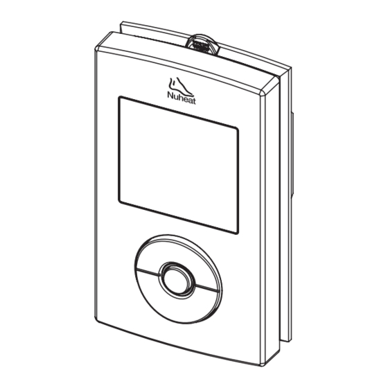
Description
The SOLO thermostat is designed to control the temperature of a
floor heating system for both 120-volt and 240-volt applications. The
thermostat can be used to control either the floor temperature or the
ambient temperature. It has a maximum load capacity of 15 A (1800
W @ 120 VAC or 3600 W @ 240 VAC).
SUPPLIED PARTS
•
One (1) thermostat
•
One (1) floor temperature sensor
•
Four (4) solderless connectors
•
Two (2) 6-32 mounting screws
•
One (1) flat-tip screwdriver
OPTIONAL ACCESSORY (SOLD SEPARATELY)
•
Honeywell outdoor sensor AC629 (for outdoor temperature and
humidity readings). Refer to section 10.
Installation
TURN OFF POWER TO THE HEATING SYSTEM AT THE MAIN POWER
PANEL TO AVOID ELECTRICAL SHOCK. THE INSTALLATION MUST
BE PERFORMED BY A QUALIFIED ELECTRICIAN.
The thermostat's housing is not watertight. Do NOT install the
thermostat in an area where it can be exposed to water or rain.
To remove the thermostat faceplate, loosen the screw (the screw
cannot be completely removed) at the bottom of the thermostat
and lift the bottom of the faceplate outwards towards you.
SOLO
1.
240 V (120 V)
GFCI test button
Screen
Select button
Up/Previous button
Down/Next button
NOTE: All wires and connections must conform to the local electrical
code. This thermostat has tinned copper wires for line and load
connections. Special CO/ALR solderless connectors must be used if
these wires are to be connected to aluminium conductors.
2.
Programmable Dual Voltage Thermostat
Connect the thermostat wires to the power supply and to the load
using solderless connectors for copper wires as shown below.
L2(N)
L1(L)
Pull the temperature sensor wires through one of the openings
on the thermostat base and connect the wires to terminals 1 and
2 (no polarity).
•
The sensor cable must not come in contact with the
electrical wires and must be routed outside the electrical
box and follow the wall down to the floor.
•
Position the sensor cable such that it does not come in
contact with the floor heating wires. The sensor must be
centered between two floor heating wires for best
temperature control.
•
Do NOT staple the sensor head (the plastic end) to the floor.
Doing so might damage the sensor. The damage might not
be noticeable during testing but can become apparent
several days later.
Network and outdoor sensor connections
(refer to sections 9 & 10)
Push the excess length of the line voltage wires back inside the
electrical box. Install the thermostat base onto the electrical box
using the provided screws.
Set the DIP switches (refer to section 2.1).
400-632-000-A
SOLO
User Guide
Power supply
Red
(White)
Black
Red
Black
L2(N)
L1(L)
Black
Red
Red
(White)
Black
Load
Floor sensor
2008-09-19
1/7
Advertisement
Table of Contents

Related Manuals for Nuheat Solo


Summary of Contents for Nuheat Solo
-
Page 1: Installation
Connect the thermostat wires to the power supply and to the load Description using solderless connectors for copper wires as shown below. The SOLO thermostat is designed to control the temperature of a floor heating system for both 120-volt and 240-volt applications. The Power supply... -
Page 2: Programming
Select button. Repeat steps 3 and 4 if you wish to modify another day. When done, press the Up or Down button until Exit is flashing and press the Select button to return to the Programming Menu. SOLO 400-632-000-A 2008-09-19... -
Page 3: Basic Operation
Home day submenu. Repeat steps 3 to 6 if you wish to modify another Period. When done, press the Up or Down button until Exit is flashing. Press the Select button to return to the Programming Menu. SOLO 400-632-000-A 2008-09-19... -
Page 4: Configurations
To modify the temperature settings, refer to sections 3.3 and 3.4. indicator will flash indicating that you are temporarily bypassing the programmed temperature. The thermostat will maintain this temperature until the start of the next period (or for 2 hours for Away mode). SOLO 400-632-000-A 2008-09-19... -
Page 5: Early Start
Using the Up or Down button, go to Backlight and press the Select button. Using the Up or Down button, choose the Backlight setting (Off / Low / High) and press the Select button. You will automatically be returned to the Programming Menu. SOLO 400-632-000-A 2008-09-19... -
Page 6: Power Outage
Network Connection the installation verified by an electrician. If you have multiple SOLO thermostats, you can connect them to It is normal that this briefly appears at power-up. Wait form a network. This allows you to: for the thermostat to obtain its reading. -
Page 7: Outdoor Sensor
4.3). To connect the sensor: year period following the initial date of purchase. During this period, NUHEAT will repair or replace, at our option and without charge, any Insert one end of a pair of AWG 18 wires through one of the two defective product which has been used under normal conditions.
Need help?
Do you have a question about the Solo and is the answer not in the manual?
Questions and answers