Table of Contents
Advertisement
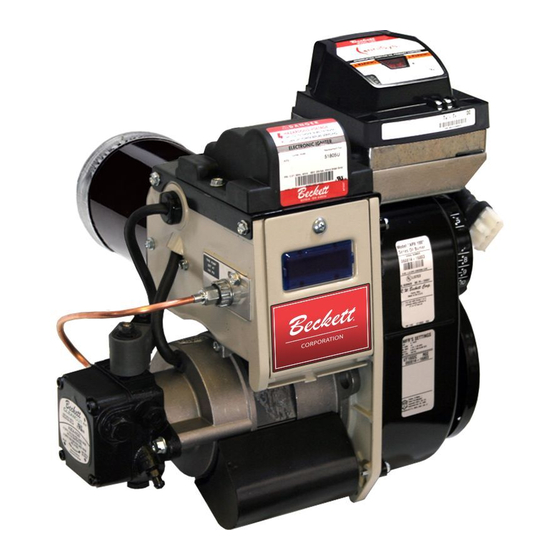
AFII 85, AFII I00, AFII 150
Types 'HLX' & 'FBX' Air Tube Combinations
Voltage: 120 volts AC/60 Hz
AFli Burner
with
Type 'HLX' Air Tube
Potential for Fire, Smoke
and Asphyxiation
Hazards
incorrect
installation,
adjustment,
or misuse
of this burner
could result
in death,
severe
personal
injury,
or substantial
property
damage.
To the Homeowner
or Equipment
Owner:
•
Please read and carefully follow all instructions
provided in this manual regarding your responsi-
bilities in caring for your heating equipment.
•
Contact a professional,
qualified service agency
for installation, start-up or service work.
To the Professional,
Qualified
Installer
or
Service
Agency:
•
Please read and carefully follow all instructions
provided in this manual before installing, starting,
or servicing this burner or heating system.
•
The installation must be made in accordance with
all state and local codes having jurisdiction.
RWB 6104 BAFII R01
Page 1
Advertisement
Table of Contents

Subscribe to Our Youtube Channel
Related Manuals for Beckett AFII85


Summary of Contents for Beckett AFII85
- Page 1 AFII 85, AFII I00, AFII 150 Types 'HLX' & 'FBX' Air Tube Combinations Voltage: 120 volts AC/60 Hz AFli Burner with Type 'HLX' Air Tube Potential for Fire, Smoke and Asphyxiation Hazards incorrect installation, adjustment, or misuse of this burner could result in death, severe...
- Page 2 Page2 RWB 6104 BAFII R01...
-
Page 3: Table Of Contents
................ lo Removing Nozzle Line for Service ......................... Nozzle installation ............................Check/Adjust Electrodes ..........................Blower Wheel Replacement ........................... Replacement Parts ......................... Replacement Parts Diagram ........................... Replacement Parts List ........................... Beckett Limited Warranty Information ....................16 Page 3 RWB 6104 BAFll R01... -
Page 4: General Information
Genera! information Owner's Responsibility To the Owner: incorrect installation, adjustment, and use of this burner could result Thank you for purchasing a Beckett burner severe personal injury, death, or sub- use with your heating appliance. Please pay attention stantial property damage... -
Page 5: General Specifications
CSA B140.0 Fuels U. S No. 1 or No. 2 heating oil only (ASTM When contacting Beckett for service information -- D396) Please record the burner serial number (and have Canada No. 1 stove oil or No. 2 furnace oil available when calling or writing). -
Page 6: Combustion Air Supply
NOZZI;: m0nufocturer's settings P_MP PRS: [lllHllll[llll]llllil[l incuding date code BJBS001R00 ..R.W. Beckett spec[fieot}on 000405-62756 number and revision 4 _ TES ÷ SPEC s U_TEST S PEC 6 ULTEST S PEC 7 ULTEST S PEC a _ T_S _ SPEC 01L I_URNER... -
Page 7: Fuel Line Installation
Site Inspect/Prepare installation Prepare the Burner • Fuel Line Installation • General CAUTION Do Not Use Teflon Tape In most cases, the burner is ready to mount to the Damage to the pump could cause impaired burn- appliance. There can be situations where the burn- er operation, oil leakage and appliance... -
Page 8: Connect Fuel Lines
Start Burner and Set Combustion • Connect Fuel Lines The R7184 primary control with valve-on delay and burner motor-off delay, shown in Figure 4, requires Do Not Install By=pass Plug a constant 120 volt AC power source supplied to the black wire on the control. (Refer to the appli- with 1-Pipe System... - Page 9 Start Burner and Set Combustion Figure 4. - Typical Wiring, R7184 Primary Control EQUIPMENT GROUND VAC BURNER __GROUND S CREW ¢ START WIRE LIMIT FROM APPLIANCE R7184 (FROM LIMIT CIRCUIT) BLACK ¢ SERIES (HOT) . L1 2°VAC PRIMARY FROM WHITE ¢...
-
Page 10: Trained Service Technician's Regular Maintenance
Trained Service Technician's Regular Maintenance • If the burner locks out on safety during bleed- Once combustion is set, tighten all fasteners on ing, reset the safety switch and complete the air dial, rear access door, and escutcheon plate. bleeding procedure. Note -- Electronic safety Start and stop the burner several times to ensure switches can be reset immediately;... -
Page 11: Removing Nozzle Line For Service
Use only nozzles having the brand, flow rate (gph), spray angle and pattern specified by the appliance manufactur- er or Beckett Residential Burner OEM Spec Guide, Part Nozzle Flow Rate by Size #6711. Nozzle flow rate U. S. gallons per hour of No. -
Page 12: Check/Adjust Electrodes
Trained Service Technician's Regular Maintenance Figure 5a. HLX Air Tube Check/Adjust Electrodes Check the electrode tip settings, as shown in Figure AR /UBE__ /SFOP SCREW SEE SP_ C_ 6a or 6b. If necessary, adjust by loosening the elec- ASSY FOI_, __ trode clamp screw and slide/rotate the electrodes hLX IIEADS _.. - Page 13 Trained Service Technician's Regular Maintenance HLX Firing Rate FBX Firing Rate Stop AFII 85 AFII 100 AFII 150 Head AFII 85 AFII 100 AFII 150 Screw 0.40-0.65 0.5-0.65 0.75-1.00 0.40-0.65 0.55-0.75 0.75-1.00 0.6-0.75 0.85-1.10 0.55-0.85 0.55-1.10 0.85-1.20 0.65-0.80 0.95-1.15 0.75-1.10 1.10-1.25 0.60-0.75 0.65-0.90...
-
Page 14: Replacement Parts Diagram
Replacement Parts Diagram For best performance specify genuine _:;__ replacement parts SK8265B Page 14 RWB 6104 BAFII R01... -
Page 15: Replacement Parts List
Replacement Parts Diagram Replacement Parts List Item Kit No. Description Item Kit No. Description Air tube combination Speci_ 51805U Igniter, Electronic 21439U Blower Wheel: AFII 85 (4-1/4") 51485 Inlet air scoop, plastic, sound insu- 21438U AFII 100 (4=1/2") lated 21438U AFII 150 (4=1/2") 51584U Housing ass'y: AFII 85 &... - Page 16 Credit will be issued to the customer unless the returned equipment is detemlined by Beckett to be out of warranty or damaged by user, in which case the equipment will be scrapped. Note: Beckett is not responsible for any labor cost for removal and replacement of equipment.
Need help?
Do you have a question about the AFII85 and is the answer not in the manual?
Questions and answers