
Subscribe to Our Youtube Channel
Related Manuals for Salicru UNINTERRUPTIBLE POWER SUPPLY ADVANCE series


Summary of Contents for Salicru UNINTERRUPTIBLE POWER SUPPLY ADVANCE series
- Page 1 UNINTERRUPTIBLE POWER SUPPLY ADVANCE series. User's manual, installation and start-up. EK459B01...
- Page 2 - 2 -...
- Page 3 General contents. 1.- INTRODUCTION. 1.1.- Gratefulness letter 1.2.- Using this manual. 1.2.1.- Used symbols and conventions. 1.2.2.- For further information and/or help. 2.- QUALITY AND STANDARD GUARANTEING. 2.1.- Management declaration. 2.2.- Standard. 2.3.- Safety and first aid. 2.4.- Environment. 3.- DESCRIPTION. 4.- PRESENTATION OF SYSTEM.
- Page 4 The equipment here described can cause important physical damages due to wrong handling. Due to this, the maintenance and/or fixing of the here described equipment must be done by SALICRU staff or specifically authorised. According to our policy of constant evolution, we reserve the right to modify the specifications in part or in whole without forewarning.
- Page 5 Preservation of the environment: The presence of this symbol in the product or in their associated documentation states that, when its useful life is expired, it will not be disposed together with the domestic residuals. In order to avoid possible damages to the environment, separate this product from other residuals and recycle it suitably. The users can contact with their provider or with the pertinent local authorities to be informed on how and where they can take the product to be recycled and/or disposed correctly.
-
Page 6: Quality And Standard Guaranteing
Quality and Environmental Management System that becomes us capable to comply the require- ments demanded by both the standards ISO 9001:2000 and ISO 14001:2004 and our Clients and concerned parts too. Likewise, the SALICRU Management is committed with the development and improvement of the Quality and Environmental Management System, through: •... - Page 7 2.2.- Standard. The UPS product ADVANCE series is designed, manufactured and commercialized in accordance with the standard EN ISO 9001 of Quality Assurance. The marking shows the conformity to the EEC Directive (quoted between brackets) by means of the application of the following standards: •...
- Page 8 Recycling the UPS ADVANCE series at the end of its useful life: SALICRU commits to use the services of authorised societies and according to the regulations, in order to treat the recovered product at the end of its useful life (contact your distributor).
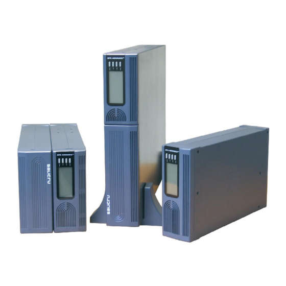
- Page 9 3.- DESCRIPTION This series is a compact and fully pure sinewave line interactive UPS, and it designs for application and environment, such as desktops, servers, workstations, and other networking equipments. This model is available in the output ratings of 750, 1000, 1500, 2000, and 3000VA.
-
Page 10: Presentation Of System
4.- PRESENTATION OF SYSTEM. 4.1.- Front Panel. The total view of the LCD (in front panel): The primary introduction to above figure: 1. Power Switch: • To turn on the UPS, press the “ON/OFF” button more than three seconds. • To turn off the UPS, press and hold this button until you hear the UPS beep ceases. - 10 -... -
Page 11: Configure Switch
2. UPS Test/ Alarm Silence Switch: • When AC utility power is available and battery is full charged, it is possible to perform self-test function by pressing and holding the “TEST” button for five seconds. • To disable alarm buzzer, press this button for a second that will turn off the alarm buzzer. Each time a new alarm event is encountered the alarm that will sound and press this button to turn off the alarm. - Page 12 • The LCD symbol indicates that the battery is working(the AC source is not available),and it will flicker every second when battery is low. • The battery symbol also could show battery level: There are four segments to indicate the amount of battery capacity remaining.
- Page 13 • Over load time out: When UPS is Over load time out, the symbol will be displayed constantly. At the same time, the symbol will be displayed constantly, and the output voltage is 0Vac 0Hz. • Battery missing: If the battery connection is not good, the LCD will display “FAULT CODE 1”. •...
- Page 14 Examples to the LCD display: If the mains supply exist: If the mains supply do not exist: - 14 -...
- Page 15 4.2.- Introducing the LCD display. polarity 4.3.- Audible alarm introduction. - 15 -...
- Page 16 4.4.- Back panel. 750/1000VA Models 1000-LV 750-LV 1000-HV 750-HV Rear panel description for LV and HV models table 1500/2000VA Models. • UPS module: The host rear panel pictures for HV and LV models are shown as below: Rear panel for HV model - 16 -...
- Page 17 Rear panel for LV model Rear panel description for LV and HV models table or AS400 • Battery module. Rear panel for HV model - 17 -...
- Page 18 Rear panel for LV model Rear panel description for LV and HV models table 3000VA model. Rear panel for HV model - 18 -...
- Page 19 Rear panel for LV model Rear panel description for LV and HV models table SNMP Slot or AS400 SNMP Slot or AS400 - 19 -...
-
Page 20: Installation
5.- INSTALLATION. 5.1.- Inspecting the Equipment. Inspect the UPS upon receipt. If the UPS has been damaged during shipment, keep the box and packing material for the carrier. Notify the carrier and dealer immediately. 5.2.- Placement. This UPS should be installed indoors with adequate airflow and free of contamination. Locate it in a clean and indoor environment, free from moisture, flammable liquids, and direct sunlight. - Page 21 5.7.- UPS Setup. All models series are designed for tower and rack purpose. They can be installed as a 19 inch equipment rack, and 3000VA can be placed in a tower (with optional stand) as well. Please follow the instruction for Tower Setup or Rack-Mount Setup. 5.7.1- Tower Setup.
- Page 22 (c) Tower form 3 3000VA model. • Tower form setup. 1. Slide down the UPS vertically and put two UPS stands at the end of the tower. 2. Place the UPS into two stands carefully. - 22 -...
- Page 23 5.7.2.- Rack-Mount Setup. 750/1000/1500/2000VA(optional) and 3000VA can be installed in 19" racks. And the UPS and external battery enclosure need 2U of valuable rack space. Use the following procedure to install UPS in a rack. 750/1000VA models (optional) 1. Align the mounting ears with screw holes on the side of the UPS. 2.
- Page 24 4. Add up the front panels for both sides. The load can be connected. 1500/2000VA models (optional) • UPS and Battery integrate into a rack form. 1. Place the UPS on a flat and in a clean place that the front side of the UPS is facing to you. 2.
- Page 25 4. Pull two covers toward the direction shown as below. 5. Align the mounting bracket with the screw holes on the each side of UPS and Battery modules and secure with the supplied screws. 6. Reinstall the UPS and Battery modules cover. 7.
- Page 26 8. Align two small mounting brackets at the rear of UPS and Battery modules and secure with the supplied screws. Install Output receptacles at the rear panel of the UPS. 9. Setup rack-mount is completed and to connect the UPS. •...
- Page 27 1. Turn on the UPS and connect the load. 2. After installing the UPS into rack, the load may be connected. Make sure the load equipment is turned off, then plug all loads into the output receptacle properly protected by a circuit breaker of fuse in accordance with national and local electrical codes.
-
Page 28: Additional Battery Installation Setup
6.- ADDITIONAL BATTERY INSTALLATION SETUP. 1500/2000VA and 3000VA include external battery port that allow to provide additional battery runtime. 1500/2000VA model has no internal battery, and 3000VA has designed an internal battery inside the UPS. Connecting battery cable to external battery port may occur sparkle if adding up additional battery. . Follow the procedure to install additional battery as below. - Page 29 3000VA model. There is one external battery port for the UPS itself. 1. Connect the supplied battery module cable from extended battery module to the external battery port of the rear of UPS. 2. If continuing to add up extended battery module, repeat above steps. - 29 -...
-
Page 30: Battery Replacement
7.- BATTERY REPLACEMENT. When the Bad Battery icon lights and there is a continuous sounding, the battery may need to be replaced. Please check the battery connection or contact your local dealer to order new battery. A battery can present a risk of electrical shock and high short circuit current. The following precautions should be observed before replacing the batteries. - Page 31 2. Disconnect the battery cable from the UPS and remove the battery retaining battery bracket. 3. Grasp the battery and pull it out from the front panel. 4. Slide the new battery into UPS. 5. Reconnect the battery cable and screw up the battery retaining battery bracket. 6.
- Page 32 3. Unscrew and remove the battery retaining battery bracket. 4. Pull the battery out onto a flat area. 5. Slide the new battery into Battery module. 6. Reconnect the battery cable and screw up the battery retaining bracket. 7. Close and reinstall the front panel back to Battery module. 3000VA model.
- Page 33 3. Unscrew the battery bracket from the Battery module. 4. Remove the battery bracket from EBM by pulling on both ends. 5. Pull the battery out (from right side) onto flat area. 6. Pull the left side of battery out onto flat area. 7.
-
Page 34: Communication Port
8.- COMMUNICATION PORT. 8.1.- R S 232 + O pto co u ple rs. D B 9 F e m ale (R S 232 + o pto co u ple rs) 8.2.- USB port: HID protocol. The USB and RS232 are unable to operate at the same time. Either only USB or DB9 can connect with RS-232 at one time, usually connecting with USB function is priority. - Page 35 The following table and diagram, shows the pin-out of female DB9 connector and its function. Do not apply values higher than 24 V DC and 1 A to the pins of the AS400 connector. Pin 1. (UPS failure). P in # D escription UPS failure Output...
-
Page 36: Troubleshooting
9.- TROUBLE SHOOTING. 9.1.- Audible Alarm Trouble Shooting. 9.2.- General Trouble Shooting. - 36 -... -
Page 37: Specification
10.- SPECIFICATION. 21.5 10.5 Optocouplers - 37 -... -
Page 38: Software Installation
11.- SOFTWARE INSTALLATION. WinPower is a brand new UPS monitoring software, which provides user-friendly interface to monitor and control your UPS. This unique software provides safely auto shutdown for multi-computer systems while power failure. With this software, users can monitor and control any UPS on the same LAN no matter how far from the UPSs. Installation procedure: 1. - Page 39 - 39 -...
- Page 40 08460 Palautordera Tel. +34 93 848 24 00 sat@salicru.com...
Need help?
Do you have a question about the UNINTERRUPTIBLE POWER SUPPLY ADVANCE series and is the answer not in the manual?
Questions and answers