Table of Contents
Advertisement
Advertisement
Table of Contents

Related Manuals for LightSpeed Technologies Cat 855


Summary of Contents for LightSpeed Technologies Cat 855
- Page 1 Classroom Audio System U s e r M a n u a l...
-
Page 3: Table Of Contents
Step 5D. Audio Input Connections Step 6. Audio Integration Step 7. Charging the REDMIKE Step 8. Set-up and Operation of REDMIKE Audio Equalization of the Cat 855 Output to Personal Assistive Listening Device Using the REDMIKE to Amplify External Audio Equipment... -
Page 4: Important Safety Instructions
IMPORTANT SAFETY INSTRUCTIONS Read these instructions. 11. Only use attachments/ accessories specified by the Keep these instructions. manufacturer. Heed all warnings. 12. Use only with a cart, Follow all instructions. stand, tripod, bracket or table specified by the Do not use the apparatus manufacturer, or sold with near water. -
Page 5: Overview
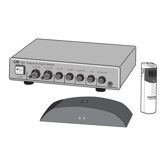
SECTION 1: OVERVIEW SYSTEM COMPONENTS AND UNPACKING The standard configuration of the CAT 855 will contain: CAT 855 Amplifier Amplifier Power Supply ISR Infrared Sensor/ Receiver and Cable Charging Cradle and Power Supply REDMIKE® Classroom Microphone... - Page 6 DRQ (x 4) NXQ (x 1) MCQ (x 1) Standard Components AMP-855 Audio amplifier/mixer PS-24V-2.5 24V/2.5A power supply for CAT 855 RX-ISR Infrared sensor/receiver with mounting bracket CA-P5E50 50’ plenum-rated Cat 5e cable REDMIKE classroom microphone with battery BA-NH2A27 AA NiMH rechargeable sensing battery for REDMIKE...
-
Page 7: Optional Components
OPTIONAL COMPONENTS Optional equipment which may be part of your CAT 855 system: REDMIKE® VC Volume Control Microphone REDMIKE Share Handheld Mic & Charger Cable LT-71 LT-71 LightMic and Charger Cable Optional Components REDMIKE VC microphone with battery REDMIKE Share handheld microphone with battery pack... -
Page 8: Front Panel Controls
FRONT PANEL CONTROLS 1. POWER SWITCH/INDICATOR: 6. ALD OUTPUT AND VOLUME: Press this button to turn the CAT This jack sends audio to external 855 ON (pushed in) or OFF. When equipment such as an assistive the POWER is switched on, the listening device (Personal FM blue LED indicator will light. -
Page 9: Rear Panel Controls
1. SPEAKER OUTPUTS (1-2): This 6. AUX OUT AND VOL: This jack euro-block connector is used sends audio to external equipment to connect the CAT 855 to the such as an assistive listening loudspeaker(s). Up to two 8-ohm device (Personal FM System) or speakers can be connected to recording device. - Page 10 3. SENSOR OUT: Connect the Cat 5 will glow blue when the ISR is sensor cable to this connection to receiving power from the CAT 855. send audio from the microphones to the CAT 855 amplifier. 2. A/B IR INDICATORS: These lights glow when the corresponding 4.
-
Page 11: Redmike Controls And Connections
REDMIKE CONTROLS AND CONNECTIONS 1. POWER BUTTON: Press this opening the compartment door, as button to turn the REDMIKE ON, it may tear, leaving fragments. press again to turn it OFF (mute). 5. AUDIO/MICROPHONE INPUT: 2. POWER/LOW BATTERY Use this input to plug in a laptop, INDICATOR: A BLUE light MP3 player or other audio indicates the REDMIKE is on and... - Page 12 CRADLE CHARGER CONTROLS AND CONNECTIONS 1. CHARGE INDICATORS: The light 2. DC POWER PORT: Connect the glows RED while the REDMIKE is 5V/1.0A DC power cord here. charging. When fully charged, the 3. OPTIONAL CHARGING PORT: light will glow GREEN. A blinking Plug the charging cord for the RED light indicates that no battery optional LT-71 or the REDMIKE...
-
Page 14: Section 2
Media Cabinet Set-up Wall-mount Set-up The included wall bracket is specifically designed to support the CAT 855. Avoid Separated Set-ups Components should be housed together. Wires should be routed back directly to the amplifier. - Page 15 Next, find a suitable location for the ISR. Poor location will cause substandard performance of the CAT 855 Classroom Audio System. The ISR should be as high as possible in the room – the ceiling is the best location, centered along the longest wall in the room.
-
Page 16: Suspended Ceiling Mount
Connect one end of the cable to the ISR. Secure wire overhead and route it back to the system. 4. Connect the other end of the Cat 5 sensor cable into the SENSOR INPUT jack on the CAT 855 amplifier. - Page 17 ISR off the bracket raceway where possible. 3. Slide the ISR onto the bracket until it “clicks” into place. 4. Connect the other end of the Cat 5 sensor cable into the SENSOR INPUT jack on the CAT 855 amplifier.
-
Page 18: Speaker Installation
3. INSTALLATION OF AMPLIFIER WALL- MOUNT BRACKET The CAT 855 systems include a bracket for optional wall-mounting. A. Determine the location: a. It should be located near a power outlet. b. Height should allow for access to front control panel, but also be in compliance with building and ADA regulations. - Page 19 DC Power Source Cable 5B. ISR CONNECTION 1. Ensure the power is still switched off. 2. Check the connection from the ISR to the CAT 855. Ensure the sensor cable is securely attached and locked into place. ISR Sensor/Receiver CAT 855 Amplifier...
- Page 20 5C. SPEAKER CONNECTION(S) Next, connect the CAT 855 to the speakers. Then, be sure any auxiliary audio sources are connected to the corresponding labeled input on the CAT 855. 1. Ensure speaker wire connections are secure and not frayed. 5D. AUDIO INPUT CONNECTIONS...
-
Page 21: Audio Integration
6. AUDIO INTEGRATION The next step in setting up your CAT 855 system is to connect it to the other multimedia devices in your classroom. You may have a computer, television, DVD/VCR player, a visual projection system or other devices. Below are instructions on how to integrate TV/VCR, CD/DVD or computer directly into the CAT 855. -
Page 22: Charging The Redmike
REDMIKE incorporates alkaline protection into the microphone design. Always use a Lightspeed rechargeable sensing battery. Replacement AA NiMH batteries may only be purchased through Lightspeed Technologies (part # BA-NH2A27). Do not attempt to charge alkaline batteries. They can overheat and expand creating a significant hazard and damaging the microphone (this is not covered by warranty). - Page 23 8. SETUP AND OPERATION OF REDMIKE Once the REDMIKE is charged, follow these steps to set it up for use. 1. Turn the CAT 855 power on. The blue LED will glow. 2. Remove the REDMIKE from the charging cradle and turn it on.
-
Page 24: Audio Equalization Of The Cat
AUDIO EQUALIZATION OF THE CAT 855 The CAT 855 uses a 4-band audio equalizer designed to optimize and fine-tune the microphone sound quality for the classroom. Below are some tips on proper system equalization: • The voice should be natural, very clear and without any audio feedback (ringing) • Walk the room listening for the... - Page 25 The Lightspeed LES-370 Personal the CAT 855. FM System requires a 3.5 mm to 5. With the CAT 855 and ALD turned 3.5 mm patch cable (part# CA- on, speak into the REDMIKE and MMC3535, not included).
- Page 26 To determine which REDMIKE is set to Channel B, you can look at the switch on the back of the mike or speak into one of the mics and watch which set of LED’s glow on the front panel of the CAT 855 (A Volume or B Volume correspond to Channels A or B).
- Page 27 CAT 855. 4. When the page is over, the audio from the CAT 855 returns to normal volume level. (For full installation details refer to the install sheet included with the...
-
Page 28: Section 3
SECTION 3: OPTIONAL ACCESSORIES OPTIONAL REDMIKE VC (Volume Control) Controls and Connections 1. POWER /MUTE BUTTON source to wirelessly transmit audio to be played through the 2. POWER/LOW BATTERY system. Alternatively, an external INDICATOR: A BLUE light microphone can be connected. indicates the REDMIKE VC is on 6. - Page 29 REDMIKE VC : Charging Before use, the REDMIKE VC should be charged. See page 22 and follow the same instructions for the REDMIKE. REDMIKE VC : Initial Set-up See page 23 and follow the same instructions for the REDMIKE to setup the REDMIKE VC.
- Page 30 OPTIONAL LT-71: Controls and Connections LT-71 LT-71 1. ON/OFF/MUTE Switch 5. AUXILIARY (AUX): Plug a laptop, MP3 player or other audio source 2. CHANNEL SELECT SWITCH (CH into this jack to wirelessly transmit A/B): Use this to choose Channel the audio signal to be played A or B.
- Page 31 LT-71: Charging 1. Ensure that the LT-71 is turned OFF. 2. Make sure the cradle charger is plugged into a wall outlet. Connect one end of the charging cable into the jack labeled CHARGER on the side of the LT-71 and plug the other end into the charging jack on the rear of the REDMIKE cradle charger.
- Page 32 LT-71: Initial Set-up Once the LT-71 is charged, follow these steps to set it up for use. 1. Turn the CAT 855 power switch to the ON position. The RED LED on the switch will glow. 2. Turn on the LT-71 and set the operating channel to “B”.
- Page 33 REDMIKE Share: Controls and Connections 1. POWER SWITCH 2. POWER/CHARGE INDICATOR: this light glows blue when turned on and turns off to indicate low battery level. When charging, the light glows red. 3. AUDIO INPUT: plug a laptop, MP3 player or other audio device into this jack to wirelessly transmit the audio signal to be played through the system.
- Page 34 REDMIKE Share: Charging 1. Ensure that the REDMIKE Share is 3. Plug the other end into the turned OFF. charging jack on the rear of the cradle charger. 2. Make sure the cradle charger is plugged into a wall outlet. 4.
- Page 35 REDMIKE Share: Initial Set-up 1. Ensure the CAT 855 is ON. The RED LED on the power switch will glow. 2. Turn on the REDMIKE Share by sliding the switch to the top position. 3. Grip the barrel in the center section.
- Page 36 (such as many DVD players) adjust the volume at the iRMC. C. If the first two options do not give optimum volume level, the last place to adjust the volume is the CH. B Volume on the CAT 855.
- Page 37 OPTIONAL IR MEDIA CONNECTOR AUDIO INTEGRATION The iRMC is designed to integrate with the CAT 855 and multiple audio sources, allowing other instructional technologies to be clearly heard throughout the classroom. Video In Projector Projector IR Sensor IR Transmission Teacher’s...
-
Page 38: Section 4
PROBLEM: Hearing Static front panel switch is on. SOLUTION: Follow these steps to • Confirm signal is being received at eliminate static. the CAT 855. The IR signal light will • Ensure sensor is in optimum be RED indicating a signal is being location (refer to sensor placement received. - Page 39 TIPS TO OBTAIN OPTIMUM AUDIO PERFORMANCE • Speak in a natural voice. A normal conversational speech levelwill provide an adequate signal. It is not necessary to increase the intensity of your voice—the audio system provides adequate amplification (approximately 5 – 10 dB) above ambient room noises. • Avoid wearing jewelry that may rub or bump against the microphone.
-
Page 40: Section 5
Repair by other than Lightspeed or its authorized service agencies will void this guarantee. Information on authorized service agencies is available from Lightspeed Technologies, Inc. Our Service Department (800.732.8999, 5 a.m. – 5 p.m., PST) will handle all your... -
Page 41: Safety Warnings And Certifications
European Union Directives: 89/336/EEC, 92/31/EEC, 93/68/ EED, and 2004/108/EC Electromagnetic Compatibility Directives. Lightspeed Technologies launched a formal product recycle program in Europe that complies with the European Union Directive 2002/96/EC on Waste Electrical and Electronic Equipment (“WEEE Directive”). Please visit our website at www.Lightspeed-tek.com for more... - Page 42 SYSTEM SPECIFICATIONS OVERALL SPECIFICATIONS Power Output 12 W per channel (24 W total) Amplifier Frequency Response 60 Hz to 20 kHz ±3 dB Carrier Frequencies (IR) 2.06/2.54; 3.2/3.7 MHz Signal-to-Noise Ratio > 73 dB Image and Spurious Rejection > 70 dB AMPLIFIER SPECIFICATIONS Receiver Type Superheterodyne...
- Page 45 LIGHT SPEED TECHNOL OGIE S 1150 9 SW HER MA N ROAD / TUALATI N, OR 97 062 T OLL FR EE : 800.732.899 9 / PHON E: 503 .68 4 .55 38 / FAX: 503.684.319 7 LI GHTSP EED-TEK.COM MN0235US01-4...
Need help?
Do you have a question about the Cat 855 and is the answer not in the manual?
Questions and answers