Advertisement
TM
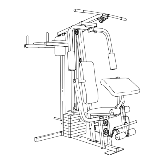
Model No. WESY95100
Serial No.
USER'S MANUAL
(Write the serial number in the
space above for reference.)
Serial Number Decal (under seat)
QUESTIONS?
As a manufacturer, we are com-
mitted to providing complete
customer satisfaction. If you have
questions, or find that there are
missing or damaged parts, we
will guarantee you complete sat-
isfaction through direct assis-
tance from our factory.
TO AVOID UNNECESSARY
DELAYS, PLEASE CALL DIRECT
TO OUR TOLL-FREE CUSTOMER
HOT LINE. The trained techni-
cians on our customer hot line
will provide immediate assis-
tance, free of charge to you.
CUSTOMER HOT LINE:
1-800-225-0653
Mon.–Fri., 6 a.m.–6 p.m. MST
CAUTION
Read all precautions and instruc-
tions in this manual before using
this equipment. Save this manual
for future reference.
PATENT PENDING
Advertisement
Table of Contents

Subscribe to Our Youtube Channel
Related Manuals for Weider Pro 9510


Summary of Contents for Weider Pro 9510
- Page 1 Model No. WESY95100 Serial No. USER'S MANUAL (Write the serial number in the space above for reference.) Serial Number Decal (under seat) QUESTIONS? As a manufacturer, we are com- mitted to providing complete customer satisfaction. If you have questions, or find that there are missing or damaged parts, we will guarantee you complete sat- isfaction through direct assis-...
-
Page 2: Table Of Contents
TABLE OF CONTENTS LIMITED WARRANTY ..............2 IMPORTANT PRECAUTIONS . -
Page 3: Important Precautions
IMPORTANT PRECAUTIONS WARNING: To reduce the risk of serious injury, read the following important precautions before using the home gym system. 1. Read all instructions in this manual and in 8. Keep hands and feet away from moving the accompanying literature before using the parts. -
Page 4: Before You Begin
BEFORE YOU BEGIN Thank you for selecting the versatile WEIDER ® 9510 Service Department toll-free at 1-800-225-0653, Home Gym System. The WEIDER ® 9510 offers a Monday through Friday, 6 a.m. until 6 p.m. Mountain selection of weight stations designed to develop every Time (excluding holidays). -
Page 5: Assembly
• Place all parts of the WEIDER 9510 in a cleared • Tighten all parts as you assemble them, unless area and remove the packing materials; do not instructed to do otherwise. - Page 6 4. Set two Weight Bumpers (19) onto the indicat- WEIDER ed bracket on the Base (4) as shown. Stack eight Weights (25) onto the Weight Bumpers (19). Be sure that the pin grooves Groove are all on the indicated side and that the “WEIDER” logos are on top.
- Page 7 5. Press the Weight Tube Bumper (64) into the end of the Weight Tube (63). Insert the Holes Weight Tube into the stack of Weights (25). Be sure that the pins on the Weight Tube are sitting in the pin grooves in the top Weight.
- Page 8 8. Wet the handle of one Press Arm (46) with soapy water. Slide a Hand Grip (31) onto the handle. Press a 1” Round Inner Cap (49) into the other end of the handle. Press a 1 3/4” Square Inner Cap (44) into the Press Arm. Attach the Press Arm (46) to one side of the Press Frame (17) with two 5/16”...
- Page 9 11. During steps 11 through 27, refer to the CABLE DIAGRAM on page 22 of this manual to verify proper cable routing. Before begin- ning this section, identify the Long Cable (23), the Medium Cable (58), and the Short Cable (35) by comparing the lengths and ends of the cables.
- Page 10 15. Route the Long Cable (23) around the “V”- Pulley (6) on the Right Arm (48). Be sure that the Cable is in the groove of the “V”- Pulley and that the Long Cable Trap (50) is turned to hold the Cable in place. Tighten the 3/8”...
- Page 11 19. Assembly steps 19 through 21 show how to complete the assembly of several pre- attached parts. The 5/8” x 9/16” Spacer (73) has been pre- attached on the wrong side of the 3 1/2” Pulley (15) for shipping purposes. Remove the 3/8”...
- Page 12 22. Locate the Medium Cable (58). Route the Medium Cable (58) under the 3 1/2” Pulley (15) attached to the lower hole in the Press Frame (17). Be sure that the end of the Cable with the ball is on the indicated side of the Press Frame and that the Cable is between the Pulley and the crossbar on the Press Frame.
- Page 13 26. Attach the end of the Medium Cable (58) to the Long “U”-Bracket (57) with a 1/4” Nylon Locknut (2) and a 1/4” Flat Washer (10). Do not completely tighten the Nylon Locknut. It should be threaded onto the end of the Cable so only a couple of threads are showing above the Nylon Locknut, as shown in the inset drawing.
-
Page 14: Front Upright (42
29. Press a 1 1/2” Square Inner Cap (32) into the Seat Frame (36). Insert the 1/4” x 2” Carriage Bolt (38) into the center hole in the Seat Plate (37). Attach the Seat Plate to the Seat (13) with two 1/4” x 1/2”... - Page 15 33. Press 3/4” Round Inner Caps (34) into the ends of both 12 1/2” Pad Tubes (28). Insert one 12 1/2” Pad Tube (28) into the Seat Frame (36). Slide a 5 1/2” Pad (30) onto each end of the Pad Tube. Insert the other 12 1/2”...
- Page 16 36. Press 1 1/2” Square Inner Caps (32) into the ends of the Left VKR Arm (79) and the Right VKR Arm (80). Press 1” Round Inner Caps (49) into the ends of the handles on the Left VKR Arm and the Right VKR Arm. Attach the Left VKR Arm (79) and the Right VKR Arm (80) to the Rear Upright (56) with two 5/16”...
- Page 17 38. Remove the decals from the decal sheet (not shown) and apply them to the home gym system in the loca- tions shown in the illustration below. HIGH PULLEY (OTHER SIDE) BUTTERFLY PRO 9510 BENCH PRESS PREACHER CURL LEG DEVELOPER LOW PULLEY 39.
-
Page 18: Adjustment
ADJUSTMENT The instructions below describe how each part of the home gym system can be adjusted. Refer to the exercise guide accompanying this manual to see how the home gym system should be set up for each exercise. IMPOR- TANT: When attaching the lat bar or nylon strap, make sure that the attachments are in the correct start- ing position for the exercise to be performed. - Page 19 ATTACHING AND REMOVING THE SEAT Set the bracket on the Seat Frame (36) on the indi- cated pins on the Front Upright (42). Attach the Seat Frame to the Front Upright with the 5/16” x 2 3/4” Carriage Bolt (14) and the Seat Knob (40). For some exercises, the Seat Frame (36) must be re- moved.
- Page 20 ADJUSTING THE SHORT CABLE The position of the Curl Bar (86) can be changed by adjusting the Short Cable (35). To adjust the Short Cable (35), remove the 5/16” x 3/4” Bolt (89), 5/16” Flat Washer (8), and 5/16” Nylon Locknut (3). Re-attach the Short Cable (35) to one of the other holes in the Leg Lever (29) with the 5/16”...
-
Page 21: Trouble-Shooting And Maintenance
TROUBLE-SHOOTING AND MAINTENANCE Inspect and tighten all parts each time you use the home gym system. Replace any worn parts immediately. The home gym system can be cleaned using a damp cloth and mild non-abrasive detergent. Do not use solvents. TIGHTENING THE CABLES Woven cable, the type of cable used on the home gym system, can stretch slightly when it is first used. -
Page 22: Cable Diagram
CABLE DIAGRAM The diagram below shows the proper routing of the Short Cable (35), the Medium Cable (58), and the Long Cable (23). Use the diagram to be sure that the cables and the cable traps have been assembled correctly. If the cables have not been correctly routed, the home gym system will not function properly and damage may occur. - Page 23 NOTES...
-
Page 24: Ordering Replacement Parts
Friday, 6 a.m. until 6 p.m. Mountain Time (excluding holidays). To help us assist you, please be pre- pared to give the following information: 1. The MODEL NUMBER of the product (WESY95100). 2. The NAME of the product (WEIDER ® 9510 Home Gym System). - Page 25 REMOVE THIS PART IDENTIFICATION CHART FROM THE MANUAL This chart is provided to help you identify the small parts used in assembly. Important: Some parts may have been pre-assembled for shipping purposes. If you cannot find a part in the parts bags, check to see if it has been pre-assembled.
- Page 26 1/2" x 1/2" Bushing (87)–1 1/2" x 3/4" Spacer (61)–2 5/8" x 9/16" Spacer (73)–1 5/8" x 3/8" Bushing (91)–1 1" x 7/8" Plastic Bushing (75)–2 1" Square Inner Cap (65)–1 1 3/4" Square Inner Cap (44)–6 1 1/2" Square Inner Cap (32)–5 2"...
- Page 28 REMOVE THIS PART LIST/EXPLODED DRAWING FROM THE MANUAL...
- Page 29 PART LIST—Model No. WESY95100 R1295A Key No. Qty. Description Key No. Qty. Description 5/16” x 2 1/2” Carriage Bolt Right Arm 1/4” Nylon Locknut 1” Round Inner Cap 5/16” Nylon Locknut Long Cable Trap Base 2” Square Outer Cap Stabilizer Chain “V”-Pulley Cable Clip...
- Page 30 EXPLODED DRAWING—Model No. WESY95100...
Need help?
Do you have a question about the Pro 9510 and is the answer not in the manual?
Questions and answers