Weider Pro 9450 User Manual
Uk manual
Hide thumbs
Also See for Pro 9450:
- Manuel de l'utilisateur (35 pages) ,
- Bedienungsanleitung (34 pages) ,
- Manuale d'istruzioni (34 pages)
Table of Contents
Advertisement
Model No. WEEVSY39120
Serial No.
Write the serial number in the
space above for reference.
Serial Number Decal (Under Seat)
QUESTIONS?
As a manufacturer, we are com-
mitted to providing complete
customer satisfaction. If you
have questions, or if there are
missing or damaged parts,
please call:
08457 089 009
Or write:
ICON Health & Fitness, Ltd.
Unit 4
Revie Road Industrial Estate
Revie Road
Beeston
Leeds, LS11 8JG
UK
email: csuk@iconeurope.com
CAUTION
Read all precautions and
instructions in this manual
before using this equipment.
Save this manual for reference.
USER'S MANUAL
Class HC Fitness Product
Visit our website at
www.iconeurope.com
Advertisement
Table of Contents

Related Manuals for Weider Pro 9450


Summary of Contents for Weider Pro 9450
- Page 1 Model No. WEEVSY39120 Serial No. Write the serial number in the USER'S MANUAL space above for reference. Serial Number Decal (Under Seat) QUESTIONS? As a manufacturer, we are com- mitted to providing complete customer satisfaction. If you have questions, or if there are missing or damaged parts, please call: 08457 089 009...
-
Page 2: Table Of Contents
TABLE OF CONTENTS WARNING DECAL PLACEMENT ............. .2 IMPORTANT PRECAUTIONS . -
Page 3: Important Precautions
IMPORTANT PRECAUTIONS WARNING: To reduce the risk of serious injury, read the following important precau- tions before using the weight system. 1. Read all instructions in this manual and in 9. Keep hands and feet away from moving parts. the accompanying literature before using the weight system. -
Page 4: Before You Begin
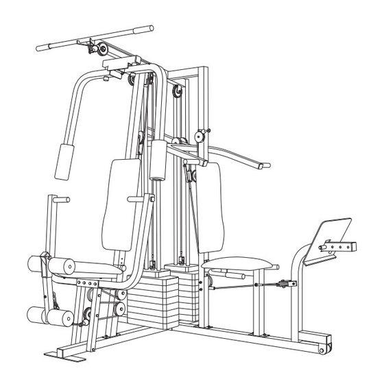
WEEVSY39120. The serial number can be found on a size and strength, or improve your cardiovascular sys- decal attached to the weight system (see the front tem, the PRO 9450 weight system will help you to cover of this manual). achieve the specific results you want. -
Page 5: Assembly
ASSEMBLY Before beginning assembly, carefully read the • Tighten all parts as you assemble them, unless following information and instructions: instructed to do otherwise. • Due to the many features of the weight system, • For help identifying the small parts used in assembly will require several hours. - Page 6 2. Slide the Rear Upright (74) and the Leg Press Upright (56) onto the indicated 5/16” x 2 1/2” Carriage Bolts (1) in the Stabiliser (5). The high side of the brackets on the Rear Upright and Leg Press Upright should be on the side shown. Hand tighten four 5/16”...
- Page 7 4. Press a 2” Square Inner Cap (27) into the end of the Top Frame (55). Press a 1 3/4” Square Inner Cap (44) into each end of the crossbar on the Top Frame. Press two Round Inner Caps (75) into the top of the crossbar.
- Page 8 7. Press a Weight Tube Bumper (64) into the end of a Weight Tube (63). Insert the Weight Tube into the Holes front stack of Weights (25). Be sure that the pin on the Weight Tube is sitting in the pin grooves in the top Weight.
- Page 9 9. Attach the upper ends of the Short Weight Guides (73) to the Top Frame (55) with a 5/16” x 6” Bolt (60), two 1/2” x 3/4” Spacers (61), and a 5/16” Nylon Locknut (3). Attach the upper ends of the Long Weight Guides (62) to the Top Frame (55) with a 5/16”...
- Page 10 12. Press a 1” Round Inner Cap (49) into one of the Press Arms (46). Press a 1 3/4” Square Inner Cap (44) into the Press Arm. Attach the Press Arm (46) to one side of the Press Frame (17) with two 5/16” x 2 1/2” Bolts (22) and two 5/16”...
- Page 11 15. See the inset drawing. Attach the Military Press Arm (84) to the Pivot Arm (80) with two 5/16” x 2 1/4” Bolts (33) and two 5/16” Nylon Locknuts (3). Press two 1 1/2” Square Inner Caps (32) into the indicated end of the Military Press Arm (84).
- Page 12 18. Wrap the High Cable (58) around a “V”-Pulley (50). Attach the “V”-Pulley and a Long Cable Trap (31) to the indicated bracket on the Front Upright (42) with a 3/8” x 2 1/2” Bolt (86) and a 3/8” Nylon Locknut (21).
- Page 13 22. See the inset drawing. Wrap the High Cable (58) around a 3 1/2” Pulley (15). Attach the Pulley and a set of Pulley Covers (77) to the upper hole in a Long Small tabs “U”-Bracket (57) with a 3/8” x 2” Bolt (12) and a 3/8” should be up.
- Page 14 25. Attach the Pulley and the 5/8” x 9/16” Spacer (7) to the Press Frame (17) with a 3/8” x 3 3/4” Bolt (88), 3/8” Washer (9), and a 3/8” Nylon Locknut (21). Be sure that the parts are oriented as shown in the drawing.
- Page 15 This chart is provided to help you identify the small parts used in assembly. The number in parenthesis below each part refers to the key number of the part from the PART LIST in the centre of this manual. Important: Some parts may have been pre-assembled for shipping purposes.
- Page 16 PART IDENTIFICATION CHART—Model No. WEEVSY39120 R1202A 3/8" x 2 1/2" Bolt (86) 5/16" x 2 1/2" Carriage Bolt (1) 1/4" x 2" Machine Screw (81) 3/8" Nylon Lock Nut (21) 3/8" Washer (9) 5/16" x 2 1/2" Bolt (22) 5/16" x 2 3/4" Bolt (11) 3/8"...
- Page 17 REMOVE THIS PART LIST/EXPLODED DRAWING FROM THE MANUAL. SAVE THIS PART LIST/EXPLODED DRAWING FOR FUTURE REFERENCE Note: Specifications are subject to change without notice.
- Page 18 EXPLODED DRAWING—Model No. WEEVSY39120 R1202A 77 9 11 8...
- Page 19 PART LIST—Model No. WEEVSY39120 R1202A Key No. Qty. Description Top Frame Leg Press Upright 5/16” x 2 1/2” Carriage Bolt Long “U”-Bracket 1/4” Nylon Locknut High Cable 5/16” Nylon Locknut 3/8” x 8” Bolt Base 5/16” x 6” Bolt Stabiliser 1/2”...
- Page 21 5/8" x 9/16" Spacer (7) 3/4" Round Inner Cap (34) 5/16" x 2" Eyebolt (35) 1" Round Cover Cap (70) 1/2" x 3/4" Spacer (61) 1" Round Inner Cap (49) Round Inner Cap (75) 1" Square Inner Cap (6) 2" Square Inner Cap (27) 1 1/2"...
- Page 22 29. Attach the end of the Low Cable (23) to the Long “U”-Bracket (57) with a 1/4” Nylon Locknut (2) and a 1/4” Washer (10). Do not completely tighten the Nylon Locknut. It should be threaded onto the end of the Cable so only a couple of threads are showing above the Nylon Locknut, as shown in the inset drawing.
- Page 23 32. Wrap the Military Press Cable (72) around a 3 1/2” Pulley (15). Attach the Pulley and a pair of Pulley Covers (77) to the Pivot Arm (80) with the 3/8” Washer (9) and the 3/8” x 5 1/4” Bolt (101). Be Large Tabs sure the Washer and Bolt are on the side shown, and that the large tabs on the Pulley...
-
Page 24: Adjustments
35. Locate the Leg Press Cable (78). Attach the end of the Leg Press Cable to the Long “U”-Bracket (57) with a 1/4” Nylon Locknut (2) and a 1/4” Washer (10). Do not completely tighten the Nylon Locknut. It should be threaded onto the end of the Cable only a couple of turns, as shown in the inset drawing. - Page 25 SEAT ASSEMBLY 37. Locate and open the parts bag labelled “SEAT ASSEMBLY.” Insert a 1/4” x 2 1/2” Carriage Bolt (92) through the centre hole in a Seat Plate (37). Attach the Seat Plate to the Leg Press Backrest (85) with two 1/4” x 3/4”...
- Page 26 41. Press a 1 1/2” Square Inner Cap (32) into the Leg Lever (29). Lubricate the 5/16” x 2 1/4” Bolt (33). Attach the Leg Lever (29) to the Front Seat Frame (36) with the Bolt and a 5/16” Nylon Locknut (3). Insert the 3/8”...
- Page 27 44. Make sure that all parts have been properly tightened. The use of the remaining parts will be explained in ADJUSTMENTS, beginning on page 21 of this manual. Before using the weight system, pull each cable a few times to be sure that the cables move smoothly over the pulleys.
-
Page 28: Weight Resistance Chart
ADJUSTMENTS The instructions below describe how each part of the weight system can be adjusted. Refer to the exercise guide accompanying this manual to see how the weight system should be set up for each exercise. IMPOR- TANT: When attaching the lat bar or nylon strap, make sure that the attachments are in the correct start- ing position for the exercise to be performed. - Page 29 ATTACHING AND REMOVING THE SEAT To attach the Seat (13), slide one of the three slots in the bracket on the Front Seat Frame (36) onto the pin on the Front Upright (42). (Note: The Seat can be attached at three different heights.) Secure the Front Seat Frame to the Front Upright with the 5/16”...
- Page 30 WEIGHT RESISTANCE CHART This chart shows the approximate weight resistance at each weight station. “Top” refers to the 6.5-lb. top weight. The other numbers refer to the 12.5-lb. weight plates. The butterfly arm resistance listed is the resistance for each butterfly arm. The actual resistance at each weight station may vary due to differences in individual weight plates, as well as friction between the cables, pulleys, and weight guides.
-
Page 31: Troubleshooting And Maintenance
TROUBLESHOOTING AND MAINTENANCE TIGHTENING THE CABLES Woven cable, the type of cable used on the weight system, can stretch slightly when it is first used. If there is slack in the cables before resistance is felt, the cables should be tightened. If any slack is felt when using the front weight stack, both the High Cable (58) and the Low Cable (23) will need to be tightened. -
Page 32: Cable Diagrams
CABLE DIAGRAMS The cable diagrams on these pages show the proper routing of the High Cable (58), the Low Cable (23), the Military Press Cable (72), and the Leg Press Cable (78). Use the diagrams to be sure that the four cables and the cable traps have been assembled correctly. - Page 33 Military Press Cable (72) and Leg Press Cable (78) Military Press Cable (72) Ball End 1—Long “U”-Bracket Rear Weight Stack—1 4—Leg Press Seat Frame Leg Press Cable (78)
- Page 34 NOTES...
- Page 35 • the KEY NUMBER and DESCRIPTION of the part(s) (see the PART LIST and EXPLODED DRAWING attached at the centre of this manual) WEIDER is a registered trademark of ICON Health & Fitness, Inc. Part No. 185547 R1202A Printed in Canada © 2002 ICON Health & Fitness, Inc.
Need help?
Do you have a question about the Pro 9450 and is the answer not in the manual?
Questions and answers