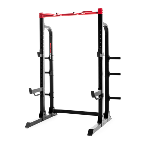
Weider Pro 7500 User Manual
Uk manual
Hide thumbs
Also See for Pro 7500:
- Manuel de l'utilisateur (44 pages) ,
- Gebruikershandleiding (44 pages) ,
- Bedienungsanleitung (44 pages)
Advertisement
Model No. WEEVSY3996.0
Serial No.
Write the serial number in the
space above for future reference.
Serial Number Decal (under seat)
QUESTIONS?
As a manufacturer, we are com-
mitted to providing complete
customer satisfaction. If you
have questions, or if there are
missing or damaged parts,
please call:
08457 089 009
Or write:
ICON Health & Fitness, Ltd.
Unit 4
Revie Road Industrial Estate
Revie Road, Beeston
Leeds, LS11 8JG
UK
Fax: 0 (44) 113 3877125
E-mail: csuk@iconeurope.com
CAUTION
Read all precautions and instruc-
tions in this manual before
using this equipment. Save this
manual for future reference.
USER'S MANUAL
Advertisement
Table of Contents

Related Manuals for Weider Pro 7500


Summary of Contents for Weider Pro 7500
- Page 1 Model No. WEEVSY3996.0 Serial No. USER’S MANUAL Write the serial number in the space above for future reference. Serial Number Decal (under seat) QUESTIONS? As a manufacturer, we are com- mitted to providing complete customer satisfaction. If you have questions, or if there are missing or damaged parts, please call: 08457 089 009...
-
Page 2: Table Of Contents
ORDERING REPLACEMENT PARTS ..........Back Cover WEIDER is a registered trademark of ICON IP, Inc. -
Page 3: Important Precautions
IMPORTANT PRECAUTIONS WARNING: To reduce the risk of serious injury, read the following important precautions before using the weight system. 1. Read all instructions in this manual and all 12. Always make sure that the weight pin is warnings on the weight system before using inserted fully into the weight stack before the weight system. -
Page 4: Before You Begin
BEFORE YOU BEGIN Thank you for selecting the versatile WEIDER reading this manual, please see the front cover of this ® 7500 weight system. The weight system offers a selec- manual. To help us assist you, note the product model tion of weight stations designed to develop every major number and serial number before contacting us. -
Page 5: Part Identification Chart
PART IDENTIFICATION CHART— Model No. WEEVSY3996.0 R0806A Refer to the drawings below to identify small parts used in assembly. The number in parentheses by each draw- ing is the key number of the part, from the PART LIST on pages 39 and 40. Note: Some small parts may have been pre-attached. - Page 6 PART IDENTIFICATION CHART— Model No. WEEVSY3996.0 R0806A M8 x 69mm Shoulder Bolt (87) M8 x 75mm Carriage Bolt (83) M10 x 68mm Bolt (85) M10 x 75mm Bolt (82) M8 x 65mm Bolt (101) M8 x 80mm Bolt (100) M10 x 65mm Button Bolt (106) M10 x 82mm Bolt (84) M10 x 63mm Bolt (79) M10 x 82mm Button Screw (92)
-
Page 7: Assembly
ASSEMBLY Make sure you have the following tools: Make Assembly Easier • Two adjustable wrenches Everything in this manual is designed to • One standard screwdriver ensure that the weight system can be assem- bled successfully by anyone. Before begin- •... - Page 8 Frame Assembly Before beginning assembly, make sure you understand the information in the Grease box on page 7. See the PART IDENTIFI- CATION CHARTS on pages 5 and 6 for help identifying small parts. Insert four M8 x 75mm Carriage Bolts (83) up through the Right Base (1).
- Page 9 5. Attach the Right Upright (2) to the Right Base (1) with two M8 Nylon Locknuts (78) and the two indicated M8 x 75mm Carriage Bolts (83). Do not tighten the Nylon Locknuts yet. 6. Orient the Rear Upright (121) so that the top Top Bracket bracket slopes toward the Left Upright (120).
- Page 10 7. Attach the Right Top Frame (4) to the Right Upright (2) with two M8 x 80mm Bolts (100), two M8 Washers (103), and two M8 Nylon Locknuts (78). Do not tighten the Nylon Locknuts yet. 8. Attach the Left Top Frame (126) to the Rear Upright (121), the Left Upright (120), and the Right Top Frame (4) with six M8 x 80mm Bolts (100), six M8 Washers (103), and six M8 Nylon...
- Page 11 10. Slide the two Weight Bumpers (71) onto the Weight Guides (18). Orient fourteen Weights (19) with the pin holes on the bottom as shown. Slide the Weights onto the Weight Guides. Insert the Weight Tube Cap (76) into the Weight Tube (20).
- Page 12 12. Attach Leg Lever Bumper (75) to the Front Leg (10) with an M4 x 16mm Self-tapping Screw (110) and an M4 Washer (104). Attach the Front Leg (10) to the Right Base (1) with two M8 Nylon Locknuts (78) and the indi- cated M8 x 75mm Carriage Bolts (83).
- Page 13 Arm Assembly 15. Attach the Butterfly Frame Brace (6) to the Right Upright (2) with two M8 x 80mm Bolts (100), two M8 Washers (103), and two M8 Nylon Locknuts (78). Do not tighten the Nylon Locknuts yet. Attach the Butterfly Frame (5) to the Right Top Frame (4) and the Butterfly Frame Brace (6) with two M8 x 80mm Bolts (100), an M10 x 75mm Button Screw (118), two M8 Washers...
- Page 14 18. Apply grease to the 44mm Bushing (136) and an M10 x 68mm Bolt (85). Then, insert the Bushing into the Military Press Frame (127). Attach the Military Press Frame inside the Left Upright (120) with the Bolt (85) and an M10 Grease Nylon Locknut (77).
-
Page 15: M8 X 69Mm Shoulder
21. Apply grease to two M10 x 82mm Bolts (84) and to the indicated locations on the Leg Press Grease Frame (123) and the Front Leg Press (132). Attach the Leg Press (124) to the Leg Press Grease Frame and the Front Leg Press Frame (123, 132) with the two Bolts (84) and two M10 Nylon Locknuts (77). - Page 16 24. Apply grease to an M10 x 110mm Bolt (93). Attach the Left Press Arm (15) to the Right Press Arm (16) with the Bolt, the Spacer, and an M10 Nylon Locknut (77). Finish attaching the Press Arms (15, 16) with two M10 x 63mm Bolts (79), two M10 Washers (80), and two M10 Nylon Locknuts (77).
- Page 17 27. Wrap the Butterfly Cable (50) under a 90mm Pulley (48). Attach the Pulley and two Half Guards (55) to the Double “U”-bracket (61) with an M10 x 50mm Bolt (97) and an M10 Nylon Locknut (77). Make sure the Half Guards are oriented as shown.
- Page 18 30. Identify the Lat Cable (49). Route the Cable up through the Left Top Frame (126) and over a 90mm Pulley (48). Attach the Pulley inside the Left Top Frame with an M10 x 82mm Bolt (84), two M10 Washers (80), two 19mm Spacers (67), and an M10 Nylon Locknut (77).
- Page 19 34. Wrap the Lat Cable (49) under a 90mm Pulley (48). Attach the Pulley and a Cable Trap (56) to the second hole in the “U”-bracket (151) with an M10 x 50mm Bolt (97), two Half Guards (55), and an M10 Nylon Locknut (77). Make sure the Cable Trap and Half Guards are oriented as shown.
- Page 20 38. Wrap the Lat Cable (49) over a 90mm Pulley (48). Attach the Pulley to the Top Center Frame (148) with an M10 x 45mm Bolt (86) and an M10 Nylon Locknut (77). 39. Set an M12 Large Washer (98) on top of the Weight Tube (20).
- Page 21 42. Route the Press Cable (133) under a 90mm Pulley (48). Attach the Pulley and a Cable Trap (56) to the Left Frame (122) with an M10 x 116mm Bolt (107), two Half Guards (55), an M10 Washer (80), and an M10 Nylon Locknut (77).
- Page 22 46. Insert a 90mm Pulley (48) into the Front Leg (10) from the indicated direction. Attach the Pulley to the Front Leg with an M10 x 68mm Bolt (85), two M10 Washers (80), two 13mm Steel Spacers (109) and an M10 Nylon Locknut (77).
- Page 23 50. Wrap the Leg Lever Cable (51) under a 90mm Pulley (48). Attach the Pulley to the Right Base (1) with an M10 x 50mm Bolt (97), two Half Guards (55), and an M10 Nylon Locknut (77). Make sure the Half Guards are oriented as shown.
- Page 24 54. Wrap the Leg Lever Cable (51) around a “V”- pulley (47). Attach the Pulley to the Right Upright (2) with an M10 x 68mm Bolt (85), two Half Guards (55), an M10 Washer (80), a Long Cable Trap (57), and an M10 Nylon Locknut (77).
-
Page 25: M6 X 60Mm Button
58. Attach the Right Seat (32) to the Right Seat Frame (8) with two M6 x 16mm Screws (88), an M6 x 32mm Screw (89), and an M6 Washer (114). Insert the Right Seat Frame (8) into the Right Frame (9). Tighten the Seat Adjustment Knob (52) into the Right Frame and the Right Seat Frame. - Page 26 62. Attach the Butterfly Cover (30) to the Butterfly Frame (5) with four M4 x 12mm Self-tapping Screws (102). 63. Attach a Shroud (21) to the Top Center Frame and Bottom Center Base (148, 147) with four M4 x 12mm Self-tapping Screws (102). Note: It may be necessary to loosen the M10 Nylon Locknuts (77) and the two indicated M10 x 82mm Bolts (84) securing the Top Center...
- Page 27 64. Attach the Curl Pad (33) to the Curl Post (11) with two M6 x 16mm Screws (88). 65. Make sure that all parts have been properly tightened. The use of the remaining parts will be explained in ADJUSTMENTS, beginning on the following page. Before using the weight system, pull each cable a few times to make sure that the cables move smoothly over the pulleys.
-
Page 28: Adjustments
ADJUSTMENTS This section explains how to adjust the weight system. Refer to the accompanying exercise guide to see the cor- rect form for each exercise. Make sure that all parts are properly tightened each time the weight system is used. Replace any worn parts immediately. - Page 29 USING THE CURL PAD To use the Curl Pad (33), remove the indicated 50mm Round Inner Cap (39) and insert the Curl Post (11) into the Front Leg (10). Tighten the Curl Adjustment Knob (58) into the Front Leg. Make sure the Curl Adjustment Knob passes through a hole in the Curl Post.
- Page 30 LOCKING THE LEG LEVER To lock or unlock the Leg Lever (12), remove the Lock Plate Pin (95) from the Lock Plate (14). Move the Lock Plate to either the position shown on the Front Leg (10), or the indicated hole in the Leg Lever. Insert the Lock Pin back through the Lock Plate.
-
Page 31: Weight Resistance Chart
WEIGHT RESISTANCE CHART The chart below shows the approximate weight resistance at each exercise station. Weight resistance shown for the butterfly arm station is for each arm. Note: The actual resistance at each station may vary due to differ- ences in individual weight plates as well as friction between the cables, pulleys, and weight guides. The maximum number of plates when performing exercises with the Butterfly Arms (25, 26) is 10. -
Page 32: Cable Diagram
CABLE DIAGRAMS The cable diagrams show the proper routing of the cables (49, 50, 133, 51). Use the diagram to make sure that the cables and the cable traps have been assembled correctly. If a cable has not been correctly routed, the weight system will not function properly and damage may occur. - Page 33 Leg Lever Cable (51) Length: 265in. (672cm)
-
Page 34: Maintenance
MAINTENANCE Make sure all parts are properly tightened each time the weight system is used. Replace any worn parts imme- diately. The weight system can be cleaned with a damp cloth and a mild, non-abrasive detergent; do not use solvents. TIGHTENING THE CABLES Woven cable, the type of cable used on the weight system, can stretch slightly when it is first used. -
Page 35: Exercise Guidelines
EXERCISE GUIDELINES THE FOUR BASIC TYPES OF WORKOUTS PERSONALIZING YOUR EXERCISE PROGRAM Muscle Building Determining the exact length of time for each workout, To increase the size and strength of your muscles, as well as the number of repetitions or sets completed, push them close to their maximum capacity. - Page 36 Rest for a short period of time after each set. The slowly as you stretch and do not bounce. Ease into ideal resting periods follow: each stretch gradually and go only as far as you can • Rest for three minutes after each set for a muscle without strain.
- Page 37 EXERCISE WEIGHT SETS REPS MONDAY Date: AEROBIC EXERCISE TUESDAY Date: EXERCISE WEIGHT SETS REPS WEDNESDAY Date: THURSDAY AEROBIC EXERCISE Date: EXERCISE WEIGHT SETS REPS FRIDAY Date: Make photocopies of this page for scheduling and recording your workouts.
- Page 38 EXERCISE WEIGHT SETS REPS MONDAY Date: AEROBIC EXERCISE TUESDAY Date: WEDNESDAY EXERCISE WEIGHT SETS REPS Date: THURSDAY AEROBIC EXERCISE Date: EXERCISE WEIGHT SETS REPS FRIDAY Date: Make photocopies of this page for scheduling and recording your workouts.
-
Page 39: Part List
PART LIST—Model No. WEEVSY3996.0 R0806A Qty. Description Qty. Description Right Base Guard Right Upright Half Guard Left Backrest Frame Cable Trap Right Top Frame Long Cable Trap Butterfly Frame Curl Adjustment Knob Butterfly Frame Brace 90mm Spacer Right Backrest Frame Pulley Plate Right Seat Frame Double “U”-bracket... - Page 40 PART LIST—Model No. WEEVSY3996.0 R0806A Qty. Description Qty. Description M10 x 116mm Bolt Front Leg Press Frame 20mm Steel Spacer Press Cable 13mm Steel Spacer 32mm Square Inner Cap M4 x 16mm Self-tapping Screw Left Frame Cap 7mm Spacer 44mm Bushing M12 Nut Top Frame Plate 40mm x 20mm x 2mm Inner Cap...
-
Page 41: Exploded Drawing
EXPLODED DRAWING—Model No. WEEVSY3996.0 R0806A... - Page 42 EXPLODED DRAWING—Model No. WEEVSY3996.0 R0806A...
- Page 43 EXPLODED DRAWING—Model No. WEEVSY3996.0 R0806A 78 116...
-
Page 44: Ordering Replacement Parts
When ordering parts, please be prepared to provide the following information: • the MODEL NUMBER of the product (WEEVSY3996.0) • the NAME of the product (WEIDER PRO 7500 weight system) • the SERIAL NUMBER of the product (see the front cover of this manual) •...
Need help?
Do you have a question about the Pro 7500 and is the answer not in the manual?
Questions and answers