Oki LD610 T User's Technical Reference
Hide thumbs
Also See for LD610 T:
- Options manual (40 pages) ,
- Quick start manual (2 pages) ,
- Safety precautions (32 pages)
Table of Contents
Advertisement
Quick Links
Advertisement
Table of Contents
Troubleshooting

Related Manuals for Oki LD610 T


Summary of Contents for Oki LD610 T
- Page 1 LD610 User’s Technical Reference 59103001...
- Page 2 © 2011 OKI Data Americas, Inc.
- Page 3 Safety Precautions Safety Precautions Please read the following information carefully before installing and using the printer. Pictographic Symbols This instruction manual and the printer labels use a variety of pictographic symbols to facilitate safe and correct use of the printer and to prevent injury to others and property damage. The symbols and meanings for them are given below.
- Page 4 Safety Precautions Caution Do not place in areas with high Power cord Loading paper humidity • Keep the power cord away from • When loading roll paper, be • Do not place the printer in areas hot devices. Getting the power careful not to get your fingers with high humidity or where con- cord close to hot devices could...
- Page 5 Safety Precautions Precautions for Installation and Handling Printer operation can be affected by the printer environment. Refer to the following instructions for installation and handling of the LD610 Series printer. Select a Safe Location Place the printer on a surface that is flat and level. Keep the printer out of high temperature and hu- midity.
-
Page 6: Table Of Contents
2.4 Loading the Carbon Ribbon (For LD610 T only) ....... . - Page 7 Table of Contents Appendix ............8-1 8.1 Optional Accessories - Cutter .
- Page 8 Table of Contents This page is intentionally left blank Page vi LD610 User’s Technical Reference...
-
Page 9: Introduction
Section 1: Introduction INTRODUCTION Thank you for your investment in this OKI printer product. This Operators Manual contains the basic information about the installation, setup, configuration, operation and maintenance of the printer. A total of eight topics are covered herein, and they are organized as follows:... -
Page 10: Unpacking
4. Set the printer on a solid, flat surface. Inspect the shipping container and printer for any sign of damage that may have occurred during shipping. Please note that OKI shall hold no liability of any damage of any kind sustained during shipping of the product. -
Page 11: Parts Identification
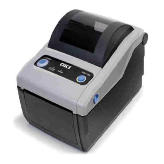
Section 1: Introduction 1.3 PARTS IDENTIFICATION Front view Operator panel ERROR LED indicator It consists of two contact buttons and two The LED lights or blinks red when an error is LED indicators (green and red). detected in the printer. During printer configuration setting, the Top cover ERROR indicator responses in conjunction... - Page 12 Section 1: Introduction 1.3 PARTS IDENTIFICATION (cont’d) Back view USB and RS232C interface on-board USB and LAN interface on-board USB and IEEE interface on-board Media inlet LAN interface terminal An opening for Fan-folded media or media To connect printer to the host computer using from unwinder to feed in to the printer.
- Page 13 Section 1: Introduction 1.2 PARTS IDENTIFICATION (cont’d) Internal view when Top cover is opened CG408TT/ CG412TT LD610 T CG408DT/ CG412DT LD610 D Print head Media guide slide lever This component is used to print on the media. Set to meet the size of the media used.
- Page 14 Section 1: Introduction This page is intentionally left blank Page 1-6 LD610 User’s Technical Reference...
-
Page 15: Installation
The following information is provided: • 2.1 Site Location • 2.2 Media Selection • 2.3 Loading Labels • 2.4 Loading the Carbon Ribbon (For LD610 T only) • 2.5 Connections LD610 User’s Technical Reference Page 2-1... -
Page 16: Site Location
For optimal print performance and durability, please use OKI-certified label and ribbon supplies on this printer. Using supplies not tested and approved for use by OKI can result in unnecessary wear and damage to vital parts of the printer, and may void the warranty. -
Page 17: Loading Labels
Section 2: Installation 2.3 LOADING LABELS 2.3.1 Loading Roll media With the power supply off, pull the cover open/close latches on both sides of the printer toward you to unlock the top cover, and then open the top cover Note: Make sure that the cover rests firmly so that it will not fall forward and injure your hands. - Page 18 Section 2: Installation 2.3 LOADING LABELS (cont’d) Close the top cover until it clicks into position. Notes: • Be careful not to get your fingers pinched while closing the top cover. • If the optional cutter or dispenser has been purchased, see Section 8.1 Optional Accessories - Cutter and Section 8.2 Optional Accessories - Dispenser on how to route the media.
- Page 19 Section 2: Installation 2.3 LOADING LABELS (cont’d) 2.3.2 Loading Fan-folded media With the power supply off, pull the cover open/close latches on both sides of the printer toward you to unlock the top cover, and then open the top cover. Note: Make sure that the cover rests firmly so that it will not fall forward and injure your hands.
- Page 20 Section 2: Installation 2.3 LOADING LABELS (cont’d) After loading the media, turn on the power. The printer is online and the ON LINE (POWER) LED lights green. When the printer is ready, press the FEED/LINE button to output the leading part of the media. ON LINE (POWER) Caution...
-
Page 21: Loading The Carbon Ribbon (For Ld610 T Only)
2.4 LOADING THE CARBON RIBBON (FOR LD610 T ONLY) The LD610 T printer enables two types of printing, Thermal transfer and Direct thermal. Thermal transfer paper media requires the use of carbon ribbon for print application. In such a scenario, it is the carbon ribbon that contains the ink that will be transferred to the media. - Page 22 Section 2: Installation 2.4 LOADING THE CARBON RIBBON (FOR LD610 T ONLY) (cont’d) Open the carbon ribbon package, and then load the ribbon in the ribbon supply unit. With the ribbon winding in clockwise direction, push in the ribbon roll to the right side of the ribbon supply unit .
- Page 23 Section 2: Installation 2.4 LOADING THE CARBON RIBBON (FOR LD610 T ONLY) (cont’d) From the ribbon supply unit, pass the carbon ribbon underneath the print head assembly to the ribbon tape wind-up unit. Affix the carbon ribbon to the ribbon core using adhesive tape, and wind it up several times in the direction shown by the turn arrow.
-
Page 24: Connections
Section 2: Installation 2.5 CONNECTIONS This section explains the power cable and interface cable connection procedures. 2.5.1 Standard interface connection LD610 Series printers have three types of Main PCBs, and each type of PCB is equipped with different types of interface to perform data communication with the host. These are described as follows. 1) RS232C and USB interface on-board 2) LAN and USB interface on-board 3) USB and IEEE 1284 interface on-board... - Page 25 • Only compatible scanner, compatible smart keyboard An example of optional keypad and OKI keypad can be connected to LD610 Series connection to the printer. printer. Refer to OKI sales representative for more details. LD610 User’s Technical Reference...
- Page 26 Section 2: Installation 2.5 CONNECTIONS (cont’d) 2.5.4 Connecting the Power Cable Warning • Be sure to connect the ground wire. Failure to do so may cause an electric shock. • Do not operate the power switch or insert/remove the power cable while your hands are wet. Doing so may cause an electric shock.
- Page 27 Section 2: Installation 2.5 CONNECTIONS (cont’d) 2.5.5 Turning On the Power Warning Do not operate the power switch or insert/remove the power cable while your hands are wet. Doing so may ERROR cause an electric shock. Beep sound ON LINE (POWER) Press the POWER on the operation panel of the unit.
- Page 28 Section 2: Installation This page is intentionally left blank Page 2-14 LD610 User’s Technical Reference...
-
Page 29: Operation And Configuration
Before using the printer, it is best to read this manual thoroughly. Otherwise, you may disturb default settings on which the instructional procedures in this manual are based. Most of the printer’s settings are controlled via standard SBPL commands or by using the provided OKI Utilities Tool application. -
Page 30: Operator Panel
Section 3: Operation and Configuration 3.1 OPERATOR PANEL The operator panel located on the top front, consists of two buttons and two LED indicators (red and green). • POWER button Press POWER button to turn on or off the printer. Press POWER button together with FEED/LINE button to enter various operating modes. -
Page 31: Operating Modes
Section 3: Operation and Configuration 3.2 OPERATING MODES You can set the printer in any of the following modes: Normal mode (including Online/Offline modes) User Test print mode Factory Test print mode Operation Setting mode: • Program download mode • Font download mode •... -
Page 32: User Test Print Mode
Section 3: Operation and Configuration 3.3 USER TEST PRINT MODE This mode produces test labels for diagnostic purposes. Preparation: Make sure the media or ribbon (if required) are properly loaded in the printer. ON LINE (POWER) ERROR Procedures Printer status Buzzer indicator indicator... - Page 33 [4.53”] (Pitch), Standard. First print-out (Settings) Print Item Contents of the print data Model Printer model name LD610 T (*), LD610 D *: “T” is printed for thermal transfer print. “D” is printed for direct thermal print. Offset Offset value (Vertical and (H)±300 (V)±300 DOT...
- Page 34 Section 3: Operation and Configuration 3.3 USER TEST PRINT MODE (cont’d) Second print-out (Protocol code setting values) Print Item NULL OFFLINE AUTO ONLINE ZERO SLASH Zero slash EURO Euro code Third print-out (Interface) USB and RS-232C interface on board Print Item Contents of the print data Selected Interface In-use interface...
- Page 35 Section 3: Operation and Configuration 3.3 USER TEST PRINT MODE (cont’d) USB and IEEE 1284 interface on board Print Item Contents of the print data Selected Interface In-use interface USB / IEEE1284 Interface 1 Interface 1 Buffer Type Buffer type Multi Protocol Protocol...
-
Page 36: Factory Test Print Mode
Section 3: Operation and Configuration 3.4 FACTORY TEST PRINT MODE This mode produces test labels for diagnostic purposes. Preparation: Make sure the media or ribbon (if required) are properly loaded in the printer. ON LINE (POWER) ERROR Procedures Printer status Buzzer indicator indicator... - Page 37 [4.53”] (Pitch), Standard. First print-out (Settings) Print Item Contents of the print data Model Printer model name LD610 T (*), LD610 D *: “T” is printed for thermal transfer print. “D” is printed for direct thermal print. Firm Ver Printer F/W version **.**.**.**...
- Page 38 3.4 FACTORY TEST PRINT MODE (cont’d) Second print-out (Settings) Print Item Contents of the print data Model Printer model name LD610 T(*), LD610 D *: “T” is printed for thermal transfer print. “D” is printed for direct thermal print. Offset Base reference correction (H)±300 (V)±300 DOT...
-
Page 39: Operation Setting Mode
Section 3: Operation and Configuration 3.5 OPERATION SETTING MODE The operation setting mode enables further selection of the functions of the printer. These are: • Program download mode • Font download mode • Default setting mode • HEX dump mode •... - Page 40 Section 3: Operation and Configuration OPERATION SETTING MODE (cont’d) ON LINE (POWER) ERROR Procedures Printer status Buzzer indicator indicator Press the FEED/LINE Program Download Three Mode short button repeatedly to Blinking green light beeps select different operation FEED/LINE setting mode cyclically. Font Download Mode Red light FEED/LINE...
-
Page 41: Program Download Mode
Section 3: Operation and Configuration OPERATION SETTING MODE (cont’d) Notes: • Press the FEED/LINE button to select the desired function, and then execute the selected function by pressing and holding the FEED/LINE button for more than 3 seconds. • When the desired interface is selected, this setting will be valid after you restart the printer. •... - Page 42 Section 3: Operation and Configuration 3.6 PROGRAM DOWNLOAD MODE (cont’d) Caution • Downloading firmware will initialize all the previous settings (set by Utilities tool application or by commands). Write down its setting details or keep a copy of FACTORY TEST PRINT for your information in case you wish to maintain the same settings in the future.
-
Page 43: Font Download Mode
Section 3: Operation and Configuration 3.7 FONT DOWNLOAD MODE In this mode, the printer is set to download fonts from the host computer. Remember to set the printer to the correct active interface to be used for the data transfer. ON LINE (POWER) ERROR Status of printer in Font Download Mode... -
Page 44: Default Setting Mode
Section 3: Operation and Configuration 3.8 DEFAULT SETTING MODE When default setting mode is selected and executed in Operation Setting mode (refer to Section 3.5 Operation Setting Mode), the printer will reset to the default setting (factory preset) as listed below. Items to be reset Default value Offset (V, H) -
Page 45: Hex Dump Mode
Section 3: Operation and Configuration 3.9 HEX DUMP MODE HEX Dump Mode allows you to print the contents of the receive buffer in a hexadecimal format. This feature allows the data stream to be examined for errors and troubleshooting. After selecting the HEX Dump Mode in Operation Setting Mode, restart the printer (refer to Section 3.5 Operation Setting Mode). -
Page 46: Printer Configurations Setting
Section 3: Operation and Configuration 3.11 PRINTER CONFIGURATIONS SETTING You can set the printer configuration by sending SBPL commands from the host computer or by using the Utilities Tool application provided (OKI Accessory CD-ROM). Category Setting item Setting contents Operation mode... - Page 47 *1. Available for USB+RS-232C specification only. *2. Available for USB+LAN specification only. *3. Use OKI port or Port 9100 when sending print request from the printer driver. *4. Available for IEEE1284+USB specification only. *5. The printer will restart in specified mode.
- Page 48 Section 3: Operation and Configuration This page is intentionally left blank Page 3-20 LD610 User’s Technical Reference...
-
Page 49: Troubleshooting
Section 4: Troubleshooting TROUBLESHOOTING If you are unable to produce printouts on the LD610 Series printer, use this section to make sure the basics have been checked, before deciding you are unable to proceed any further. This section is divided into four parts: •... -
Page 50: Error Signal Troubleshooting
Section 4: Troubleshooting 4.1 ERROR SIGNAL TROUBLESHOOTING The ON LINE (POWER) and ERROR indicators light or flash in different colors and patterns listed below to alert user that an error has occurred on the printer. [Indicator sequence (as shown from left to right): Off, Red light, Green light]... - Page 51 Section 4: Troubleshooting 4.1 ERROR SIGNAL TROUBLESHOOTING (Cont’d) ON LINE ERROR Contents (POWER) Buzzer Causes Corrective Actions Minor error Cover open Blinking red 3 short 1) Cover is not closed 1) Close the cover. beeps properly. sound Sensor error 1) Wrong sensor level. 1) Level adjustment.
-
Page 52: Troubleshooting Table
Foreign material on print head and/or platen roller. Clean as required. Foreign material on labels. Use higher quality media. Use only OKI-certified media. Defective print head. Replace print head as required. Ribbon stock conditions are only applicable to LD610 T printers. Page 4-4 LD610 User’s Technical Reference... - Page 53 Defective print head. Replace print head as required. SMEARED PRINT IMAGES Poor media quality Use higher quality media. Use only OKI-certified media. Foreign material on print head and platen roller Clean print head and platen roller. Foreign material on labels Use higher quality media.
-
Page 54: Interface Troubleshooting
Click on System within the new window. Click on the Device Manager tab. Ensure that the View Device By Type is checked. Scroll to OKI-USB Device and ensure that errors do not exist. Reinstall as required. Reboot the PC and the printer. RS232 SERIAL INTERFACE TROUBLESHOOTING STEP Ensure the correct interface module is correctly installed. -
Page 55: Test Print Troubleshooting
Section 4: Troubleshooting 4.3 INTERFACE TROUBLESHOOTING (Cont’d) PARALLEL INTERFACE TROUBLESHOOTING STEP Ensure the interface module is correctly installed. Run self-test to verify. Ensure the printer cable is connected to the appropriate LPT port on the host computer. If using a Windows printer driver, ensure the correct port is selected. - Page 56 Section 4: Troubleshooting This page is intentionally left blank Page 4-8 LD610 User’s Technical Reference...
-
Page 57: Cleaning And Maintenance
Section 5: Cleaning and Maintenance CLEANING AND MAINTENANCE This section provides information on user maintenance for the LD610 Series printer. The following information is covered here: • 5.1 Cleaning The Print Head, Platen and Rollers • 5.2 How To Clean The Printer (Cleaning Kit) •... -
Page 58: Cleaning The Print Head, Platen And Rollers
Furthermore, dirt can accumulated along the label path, affecting parts like sensors and guides, and reducing their performance. Therefore, it is important to clean these important components periodically. The printer cleaning kit and cleaning sheets can be purchased from your authorized OKI representative. When to clean with a cleaning kit ♦... -
Page 59: How To Clean The Printer (Cleaning Sheet)
Section 5: Cleaning and Maintenance 5.2 HOW TO CLEAN THE PRINTER (CLEANING KIT) (cont’d) Locate the I-Mark sensor and Gap sensor on the left Media guide I-Mark and Gap Media guide. sensor is underneath the Dab a cotton cloth with the same cleaning solution. Clean media guide any foreign matter from the exposed surface of the media guides and sensor. -
Page 60: Easy Replacement Of Parts
5.4.1 Releasing/ Replacing the Print Head The print head on the printer is a user-replaceable item. If it becomes damaged for any reason, it can be easily removed and replaced. Contact your local OKI representative for information on obtaining a new print head. - Page 61 Section 5: Cleaning and Maintenance 5.4 EASY REPLACEMENT OF PARTS (cont’d) Align the two circular recess of the print head bracket to the two springs attached to the top cover frame. At the Hooks same time, fix the fulcrum shaft of the print head bracket to the hooks.
- Page 62 Section 5: Cleaning and Maintenance 5.4 EASY REPLACEMENT OF PARTS (cont’d) 5.4.2 Releasing/ Replacing the Platen roller Make sure the printer is powered off and remove the power cable. Lift the Top Cover. Locate the two platen bearings on each side of the platen roller, and turn the handles in the direction as shown.
-
Page 63: Adjusting Print Quality
Section 5: Cleaning and Maintenance 5.5 ADJUSTING PRINT QUALITY Print quality can be optimized with regular cleaning and maintenance of the print head and components along the label path. Additionally, you can fine-tune print quality by adjusting print darkness and print speed settings. When adjusting the printer for optimum print quality, a barcode verifier system is highly recommended for evaluating the printouts. - Page 64 Section 5: Cleaning and Maintenance This page is intentionally left blank Page 5-8 LD610 User’s Technical Reference...
-
Page 65: General Specifications
Section 6: General Specifications GENERAL SPECIFICATIONS 6.1 PRINTER BASIC SPECIFICATIONS MODEL NAME LD610 D LD610 T PHYSICAL CHARACTERISTICS Width 179 mm (7.05”) Depth 238 mm (9.37”) Height 173 mm (6.81”) Weight 1.7 kg (3.7 lbs.) 1.9 kg (4.19 lbs.) POWER SUPPLY (AC ADAPTER) - Page 66 Section 6: General Specifications MODEL NAME LD610 D/ LD610 T MEDIA (Be sure to use media manufactured or certified by OKI) Direct Thermal / Thermal Transfer depending on print model (D or T) Type Roll stock or Fan-fold Wind Direction Roll stock: Face In or Face out winding Maximum outer diameter: 128 mm (5.04”) with Inner core diameter: 40 mm (1.5”)
- Page 67 Section 6: General Specifications MODEL NAME LD610 D LD610 T RIBBON (Be sure to use ribbon manufactured or certified by OKI) Wind Direction Face Out Winding Method Paper core Roll Diameter Maximum outer diameter: 38 mm (1.4”) Core Diameter Inner core diameter: 12.7 mm (0.5”) —...
- Page 68 Section 6: General Specifications MODEL NAME LD610 D LD610 T SELF-DIAGNOSIS Cover Open Detection Cover Open Detection Paper End Detection Paper Detection Test Print Test Print Cutter error (Only available if installed) Ribbon end Detection Cutter error (Only available if installed)
- Page 69 Section 6: General Specifications MODEL NAME LD610 D LD610 T BARCODE CAPABILITIES UPC-A/UPC-E, EAN8/13, CODE39, CODE93, CODE128, GS1-128 (UCC/EAN128), CODABAR(NW-7), ITF, Industrial 2 of 5, Matrix 2 of 5, Linear Bar Codes BOOKLAND, MSI, POSTNET, GS1 DataBar (RSS) * GS1 DataBar is new version of RSS-14.
- Page 70 Section 6: General Specifications MODEL NAME LD610 D LD610 T HARDWARE AND RELATED Operation keys POWER and FEED/LINE buttons ON LINE (POWER): Green LED Indicators ERROR: Red LED Built-in buzzer Buzzer • On/ off switchable buzzer (specified by command) • No volume control function available Antibacterial finishing for external cover and operative parts.
-
Page 71: Optional Accessories Specifications
Label only * Some restrictions may apply to some label types depending on the substrate, Media Type adhesive, paper size, and environment. Refer to OKI representative on the labels to be used. * Perforated liner and split liner cannot be used. - Page 72 Section 6: General Specifications This page is intentionally left blank Page 6-8 LD610 User’s Technical Reference...
-
Page 73: Interface Specifications
Section 7: Interface Specifications INTERFACE SPECIFICATIONS This section presents the interface types and their specifications for the LD610 Series printers. These specifications include detailed information to assist in the selection of the most appropriate method for the printer to interface with the host. The following information is presented in this section: •... -
Page 74: Rs232C Serial Interface
Section 7: Interface Specifications 7.2 RS232C SERIAL INTERFACE 7.2.1 Basic Specifications of RS-232C Serial Interface This interface complies with the RS-232C standard. Interface connector DB-9S or equivalent (Male) Cable length: 5m or less Communication Use Printer configuration tool or <I2> command to setup. settings <I2>abcde Parameter... - Page 75 Section 7: Interface Specifications 7.2 RS232C SERIAL INTERFACE (cont’d) Function descriptions Function Description Baud rate setting Select the data rate (bps) for the RS232 port. Data bit length Sets the printer to receive either 7 or 8 bits of data for each byte transmitted. Parity setting Selects the type of parity used for error detection.
- Page 76 Section 7: Interface Specifications 7.2 RS232C HIGH SPEED SERIAL INTERFACE (cont’d) 7.2.2 Ready/Busy This protocol controls the reception of print data only by the control of hardware signal. Use the command <I2> to toggle between single item buffer and multi item buffer. When the print data (STX ESC+”A”~ ESC+”Z”...
- Page 77 Section 7: Interface Specifications 7.2 RS232C HIGH SPEED SERIAL INTERFACE (cont’d) 7.2.3 X-ON/X-OFF This transmission protocol informs the host if the printer is ready to receive data, by sending the “XON” (Hex 11H) or “XOFF” (Hex 13H) code. When the print data (STX ESC+”A”~ ESC+”Z” ETX) is sent from the host in the conditions below, received data may be incorrect.
-
Page 78: Ieee 1284 Parallel Interface
Interface type Use Printer configuration tool or <DI> command. <DI>a Parameter Item Value Decription Interface IEEE1284 Maximum receive buffer capacity Buffer near full occurred Remaining 0.25MB Buffer near full released Remaining 0.5MB DeviceID LD610 “MFG:OKI;CMD:PCL,MPL;MDL:LD610;” Page 7-6 LD610 User’s Technical Reference... - Page 79 Section 7: Interface Specifications 7.3 IEEE 1284 PARALLEL INTERFACE (cont’d) 7.3.2 Pin Assignments Pin assignment of each signal for the Centronics standard (Compatible Mode) is as follows. Note that the connection of the IEEE1284 standard complies with the IEEE1284-B standard. PIN No.
- Page 80 Section 7: Interface Specifications 7.3 IEEE 1284 PARALLEL INTERFACE (cont’d) 7.3.3 Input/Output Signals The details of each signal line for the Centronics standard (Compatible Mode) are as follows. Note that each signal line complies with the IEEE1284 standard. Signal Description STROBE Input Synchronization signal that requires low active pulse to read...
-
Page 81: Universal Serial Bus (Usb) Interface
Section 7: Interface Specifications 7.4 UNIVERSAL SERIAL BUS (USB) INTERFACE This printer supports the USB 2.0-compliant interface and the transfer rate at 12.5 Mbits/second. 7.4.1 Basic Specifications of USB interface The USB interface is available with all three types of boards. Interface connector Series B plug Cable length: 5m or less (Twisted Pair Shielded) - Page 82 Section 7: Interface Specifications 7.4 UNIVERSAL SERIAL BUS (USB) INTERFACE (cont’d) 7.4.3 Host Computer Settings Installation of USB Standard Print Support It is necessary to install the USB driver in addition to the printer driver to perform print operation via the USB port.
-
Page 83: Local Area Network (Lan) Ethernet
[Initializing LAN configuration information] LAN configuration information will be initialized through [All Clear] of Factory Clear Mode. For more details, refer to the authorized OKI servicing personnel. Interface type Use Printer configuration tool or <DI> command. - Page 84 Section 7: Interface Specifications 7.5 LOCAL AREA NETWORK (LAN) ETHERNET (cont’d) Communication The following settings can be configured via the Printer configuration tool or com- configuration mands. Item Command Setting range LAN mode <I3> Protocol for driver (STATUS4) cyclic response mode * Protocol for driver (STATUS4) ENQ response mode * STATUS3 *...
- Page 85 Section 7: Interface Specifications 7.5 LOCAL AREA NETWORK (LAN) ETHERNET (cont’d) 7.5.3 TCP/IP Specifications In TCP/IP protocol environment, LPD and FTP are provided for printing. TELNET is provided for the setup of various variables, and ARP, RARP and BOOTP/DHCP for the setup of IP address are available. In socket connection, the printing operation and the status are monitored.
- Page 86 In MS-DOS command prompt, type in [TELNET xxx.xxx.xxx.xxx (IP address)] and enter user name and password to advance to the display below. OKI PRINTER ModelName TELNET server. Copyright 2011(C) OKI Data Americas, Inc. login: root ‘root’ user needs password to login password: User ‘root’...
- Page 87 Notes 1) For the detailed On-board LAN interface settings, refer to the included [Setup Guide] and the Network Utility of [OKI Accessory CD-ROM]. 2) To open/close Print data port (Port1024), Status port (Port1025) or Sending/Receiving port (Port9100), make sure to close and open the port at intervals of approximately 150ms to 200ms. If you don't have enough time from closing to opening the port, it may result in double connection.
- Page 88 Section 7: Interface Specifications This page is intentionally left blank Page 7-16 LD610 User’s Technical Reference...
-
Page 89: Appendix
Section 8: Appendix APPENDIX The following information is provided: • 8.1 Optional Accessories - Cutter • 8.2 Optional Accessories - Dispenser • 8.3 Positions of sensors and options • 8.4 Operation Mode Selection • 8.5 Base Reference Point • 8.6 Offset position Adjustment •... -
Page 90: Optional Accessories - Cutter
Section 8: Appendix 8.1 OPTIONAL ACCESSORIES - CUTTER The cutter should only be installed by OKI qualified servicing personnel. 8.1.1 To route the media when the cutter is installed Loading of the media for cutter unit is similar to the usual procedure as explained in Section 2.3 Loading Labels . -
Page 91: Optional Accessories - Dispenser
(Please contact an authorized OKI Representative for replacement.) —456 8.2 OPTIONAL ACCESSORIES - DISPENSER Dispenser should only be installed by OKI qualified servicing personnel. 8.2.1 To route the label when the dispenser is installed With the power supply off, pull the cover open/close Pressure... - Page 92 Section 8: Appendix 8.2 OPTIONAL ACCESSORIES - DISPENSER (cont’d) If the paper is not taut, roll the paper on the media holder so that the paper is taut. Next, tightly close the pressure bracket with the liner (backing paper) passing through it. Close the top cover until it clicks into position.
-
Page 93: Positions Of Sensors And Options
Section 8: Appendix 8.3 POSITIONS OF SENSORS AND OPTIONS 7.3mm (0.29”) 5.0mm (0.19”) I-Mark sensor 46.3mm 34.9mm Gap sensor (1.82”) (1.37”) Print head 14.5mm 20.6mm 21.1mm (0.57”) (0.81”) Tear-off/ Nonsepa(Linerless) (0.83”) Dispenser Cutter LD610 User’s Technical Reference Page 8-5... -
Page 94: Operation Mode Selection
Section 8: Appendix 8.4 OPERATION MODE SELECTION There are five modes of printer operation: Continuous, Tear-off, Cutter, Dispense and Linerless (Nonesepa) mode. The differences are the ways in which the label and paper backing are ejected. Before printer configuration, one must determine which mode will be used. This section identifies the functional differences among the five. -
Page 95: Base Reference Point
Section 8: Appendix 8.5 BASE REFERENCE POINT The base reference point is the point at which one determines the print and cut positions. The base reference position differs, depending on the print mode or the label pitch sensor to be used. Continuous Mode I-Mark I-Mark (CX-compatible) - Page 96 Section 8: Appendix 8.5 BASE REFERENCE POINT (cont’d) Dispenser Mode I-Mark I-Mark (CX-compatible) Base print Base print Base print and dispense and dispense and dispense position position position I-Mark I-Mark (CX-compatible) Base print Base print position position 8.5.1 Base Reference point Adjustment Print head Print Position Offset refers to the vertical and horizontal shifting of the entire print area, relative to the start position of printing (V=0, H=0),...
-
Page 97: Offset Position Adjustment
This setting adjusts the option (Cutter, Dispenser, Tear off) stop position after a print out. The Offset position can be adjusted by using OKI Utilities Tool application or by sending command <PO> from the host. The setting range is within ±99 dots. A positive value moves the leading edge of the label forward (away from the print head) while a negative value moves the leading edge of the label back toward the mechanism. -
Page 98: Paper End
Section 8: Appendix 8.7 PAPER END 8.7.1 Roll Label End When the Label End is less than 40mm (1.57”) from the end of I-Mark I-Mark Approximately 40mm (1.57”) or Media feed direction less The printer behavior when paper end is detected is as follows: •... -
Page 99: Ribbon End
The paper end detection is performed by the I-Mark sensor, therefore, the above motion may not occur depending on the adjustment of the I-Mark sensor. 8.8 RIBBON END Ribbon End detection is only available for LD610 T printers. Printer behavior when ribbon near end is detected is as follows: •... - Page 100 Section 8: Appendix This page is intentionally left blank Page 8-12 LD610 User’s Technical Reference...
Need help?
Do you have a question about the LD610 T and is the answer not in the manual?
Questions and answers